(Ebook English) Us Army Engineer Course En5260 Construction Equipment Repairer (Hydraulic Systems)
Bạn đang xem bản rút gọn của tài liệu. Xem và tải ngay bản đầy đủ của tài liệu tại đây (3.04 MB, 82 trang )
CONSTRUCTIONEQUIPMENT REPAIRER
(HYDRAULIC SYSTEMS)
Subcourse EN 5260
EDITION B
United States (US) Army Engineer School
Fort Leonard Wood, Missouri 65473
4 Credit Hours
Edition Date: November 1999
SUBCOURSE OVERVIEW
This subcourse is designed to teach the basic skills required to adjust and repair
hydraulic pumps and valves used on engineer construction equipment. Information is
provided on positivedisplacement pumps and control valves and the procedures
required to disassemble, adjust or repair, and reassemble them. This subcourse is
presented in two lessons, each corresponding to a terminal learning objective.
There are no prerequisites for this course.
This subcourse reflects the doctrine which was current at the time it was prepared. In
your own work, always refer to the latest official publications.
Unless otherwise stated, the masculine gender of singular pronouns is used to refer to
both men and women.
TERMINAL LEARNING OBJECTIVE:
ACTION:
You will learn to identify, disassemble, adjust or repair, and
reassemble hydraulic pumps and valves used on engineer
construction equipment.
CONDITION:
You will be given this subcourse and an ACCP examination
response sheet.
i
EN 5260
STANDARD:
EN 5260
To demonstrate competency of this task, you must attain a
minimum score of 70 percent on the subcourse examination.
ii
TABLE OF CONTENTS
Section
Page
Subcourse Overview............................................................................................................i
Administrative Instructions.............................................................................................iii
Grading and Certification Instructions............................................................................iv
Lesson 1: Hydraulic Pumps...........................................................................................11
Part A: PositiveDisplacement Pumps.....................................................................12
Part B: Gear Pump ...................................................................................................15
Part C: Vane Pump .................................................................................................111
Part D: Piston Pump ...............................................................................................112
Practice Exercise.......................................................................................................119
Answer Key and Feedback.......................................................................................122
Lesson 2: Hydraulic Valves............................................................................................21
Part A: PressureControl Valves...............................................................................22
Part B: DirectionalControl Valves...........................................................................25
Part C ControlValve Repair.....................................................................................28
Practice Exercise.......................................................................................................215
Answer Key and Feedback.......................................................................................218
Examination....................................................................................................................E1
Appendix A: List of Common Acronyms.......................................................................A1
Appendix B: Recommended Reading List....................................................................B1
Appendix C: Metric Conversion Chart.........................................................................C1
iii
EN 5260
Appendix D: Publication Extracts ...............................................................................D1
Student Inquiry Sheets
EN 5260
iv
ADMINISTRATIVE INSTRUCTIONS
1.
Number of lessons in this subcourse: Two.
2.
Materials you will need in addition to this booklet are a number two pencil, the
ACCP examination response sheet, and the preaddressed envelope you received with
this subcourse.
3.
Supervisory requirements: None.
4.
The following publications provide additional information about the material in
this subcourse. You do not need these publications to complete this subcourse.
•
FM 5499. Hydraulics. 1 August 1997.
•
Soldier Training Publication (STP) 562B1SM. Soldier's Manual, MOS 62B,
Construction Equipment Repairer Skill Level 1. 25 September 1990.
•
STP 562B24SMTG. Soldier's Manual and Trainer's Guide: MOS 62B,
Construction Equipment Repairer (Skill Level 2/3/4). 15 October 1990.
•
TM 52350262201. Unit Maintenance Manual Vol 1 of 2 for Armored
Combat Earthmover (ACE), M9 (NSN 2350008087100) (This Item is
Included on
EM 0035). 3 January 1997.
•
TM 52350262202. Unit Maintenance Manual, Vol 2 of 2 for Armored
Combat Earthmover (ACE), M9 (NSN 2350008087100) (This Item is
Included on
EM 0035). 3 January 1997.
•
TM 5241023720. Unit Maintenance Manual for Tractor, Full Tracked, Low
Speed: DED, Medium Drawbar Pull, SSN M061, Tractor With Ripper, (NSN
2410012230350) Tractor With Winch, (2410012237261) Tractor With
Ripper and Winterized Cab, (2410012532118) Tractor With Winch and
Winterized Cab, (2410012532117) (This Item is Included on EM 0119).
30 March 1993.
•
TM 5241023734. Direct Support and General Support Maintenance Manual
for Tractor, Full Tracked, Low Speed: DED, Medium Drawbar Pull, SSN
M061 Tractor With Ripper, (NSN 2410012230350) Tractor With Winch,
(2410012237621) Tractor With Ripper and Winterized Cab, (241001253
2118) Tractor With Winch and Winterized Cab, (2410012532117) (This Item
is Included on EM 0119). 30 March 1993.
v
EN 52605
•
TM 5380526220. Organizational Maintenance, Loader, Scoop Type, DED,
4 x 4, Articulated Frame Steer, 21/2 Cubic Yard (J. I. Case Model MW24C)
(NSN 3805011504814) (This Item is Included on EM 0115).
1 September 1987.
•
TM 5380526234. Direct Support and General Support Maintenance Manual
For Loader, Scoop Type, DED, 4 x 4, Articulated Frame Steer, 21/2 Cubic
Yard (J. I. Case Model MW24C) (NSN 3805011504814) (This Item is
Included on EM 0115). 1 September 1987.
GRADING AND CERTIFICATION INSTRUCTIONS
Examination: This subcourse contains a multiplechoice examination covering the
material in the two lessons. After studying the lessons and working through the
practice exercises, complete the examination. Mark your answers in the subcourse
booklet, then transfer them to the ACCP examination response sheet. Completely
black out the lettered oval that corresponds to your selection (A, B, C, or D). Use a
number two pencil to mark your responses. When you complete the ACCP examination
response sheet, mail it in the preaddressed envelope you received with this subcourse.
You will receive an examination score in the mail. You will receive four credit hours for
successful completion of this examination.
EN 5260
vi
THIS PAGE IS INTENTIONALLY LEFT BLANK.
vii
EN 52607
LESSON 1
HYDRAULIC PUMPS
Critical Tasks: 0512351180
0512352186
OVERVIEW
LESSON DESCRIPTION:
This lesson will introduce you to positivedisplacement pumps used on engineer
construction equipment. Included are the steps required to disassemble pumps, repair
or replace components, and reassemble pumps.
TERMINAL LEARNING OBJECTIVE:
ACTION:
You will learn the types of positivedisplacement pumps commonly
used on engineer construction equipment and the procedures
required to disassemble, repair, and reassemble them.
CONDITION:
You will be given the material contained in this lesson. You will
work at your own pace and in your own selected environment with
no supervision.
STANDARD:
You will correctly answer the practice exercise questions at the
end of the lesson.
REFERENCES:
The material contained in this lesson was derived from STP
562B1SM, STP 562B24SMTG, TM 52350262201, TM
52350262202, TM 5241023734, TM 5380526220, and
TM 5380526234.
INTRODUCTION
Hydraulics is the science of using force and motion to move confined liquid. In a
hydraulic device, a transfer of energy takes place when liquid is subject to pressure.
The following four basic principles govern hydraulics:
1-1
EN 5260
•
Liquids have no shape of their own; they conform to the shape of their
container.
•
•
Liquids are incompressible.
Liquids transmit applied pressure in all directions.
•
Liquids provide increased force.
The following key facts will help you gain an understanding of hydraulics:
•
Hydraulic power is generated from mechanical power.
•
Hydraulic energy is achieved by converting hydraulic power to mechanical
energy.
•
Hydraulic energy consists of potential (pressure energy), kinetic (energy of
moving liquids), and heat (energy of resistance to fluid flow [friction]).
•
Hydraulic energy is neither created nor destroyed, only converted to
another form.
•
Energy in a hydraulic system is considered either work (gain) or heat (loss).
•
Heat is created and energy is lost when a moving liquid is restricted.
PART A: POSITIVEDISPLACEMENT PUMPS
11. General. Pumps are used to lift or transport liquid. They may raise the liquid
level or force the liquid through a hydraulic system.
a. Pumps in a hydraulic system are used to convert mechanical energy to
hydraulic energy. Mechanical power creates a partial vacuum at the pump's inlet port
so that atmospheric pressure in the reservoir can force liquid through the inlet line and
into the pump. Mechanical power then delivers this liquid to the outlet port, forcing
the liquid into the hydraulic system.
b. Positivedisplacement pumps are the most common hydraulic pumps on
engineer construction equipment. These pumps have a rotary motion that carries
liquid from the inlet port to the outlet port. They produce a pulsating flow of liquid.
Because these pumps have a positive internal seal to prevent leakage, their output is
relatively unaffected by system variations. For example, if an outlet port is blocked,
pressure in the pump will increase until the equipment stalls or the pump's motor fails.
Positive displacement pumps are classified according to the element that transmits the
liquidgear, vane, or piston.
EN 5260
1-2
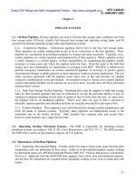
12. Gear Pump. The gear pump (Figure 11) consists of a driving gear and a driven
gear enclosed in a fitted housing. The gears rotate in opposite directions, and the gear
teeth mesh in the housing between the inlet and outlet ports. As the teeth of the two
gears separate, a partial vacuum is formed, which draws liquid through the inlet port
into chamber A. Liquid in chamber A is then trapped between the teeth of the two
gears and the housing and is carried through two paths to chamber B. As the teeth
mesh again, liquid is forced through the outlet port.
Chamber A
To inlet port
Driven gear
Housing
Driving gear
Chamber B
Outlet port
Figure 11. Gear pump
13. Vane Pump. In a vane pump, a slotted rotor splined to the drive shaft rotates
between fitted side plates inside an elliptical or circleshaped ring (Figure 12, page
14). Polished, hardened vanes slide in and out of the rotor slots and follow the ring's
contour by centrifugal force. Chambers formed between succeeding vanes carry oil
from the inlet port to the outlet port. A partial vacuum is created at the inlet as the
space between the vanes increases, forcing oil through the outlet as the area in the
pumping chamber decreases. Because the normal wear points on a vane pump are the
tips and the ring surface, these parts are specially hardened and ground.
1-3
EN 5260
Slotted
rotor
Drive
shaft
Elliptical
ring
Inlet
port
Outlet
port
Vanes
Figure 12. Vane pump
a. The vane pump is the only pump designed with automatic wear compensation.
As wear occurs, the vanes slide out of the rotor slots and continue to follow the ring's
contour. Thus, efficiency remains high throughout the life of the pump.
b. Vane pumps can be assembled to rotate either left or right. Corresponding
arrows stamped on the pump's body and cartridge indicate rotation direction. Rotation
is also indicated in the model number. Pumps assembled for lefthand rotation
(counterclockwise when viewed from the driveshaft end) have the letters "LH" added to
the model number. Pumps assembled for righthand rotation have no markings.
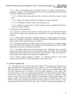
14. Piston Pump. On an inline piston pump, the drive shaft and the cylinder block
are on the same centerline (Figure 13). Reciprocation of the pistons occurs when the
pistons run against a swash plate as the cylinder block rotates. The drive shaft turns
the cylinder block, which carries the pistons around the shaft. The piston shoes slide
against the swash plate and are held against it by the shoeretainer plate. The angle of
the swash plate causes the cylinders to reciprocate in their bores. When a piston begins
to retract, the opening on the end of the bore slides over the inlet slot in the valve plate
and oil is drawn into the bore through less than onehalf a revolution of the cylinder
block. A solid area is created in the valve plate, and the piston retracts. As the piston
begins to extend the opening, the cylinder barrel moves over the inlet port and oil is
forced through the outlet port.
a. The major components of a piston pump consist of a housing, a
bearingsupported drive shaft, a rotating group, a shaft seal, and a valve plate. The
valve plate contains the inlet and outlet ports and functions as the back cover. The
rotating group includes a cylinder block, which is splined to the drive shaft; a splined
spherical washer; a cylinderblock spring; nine pistons with shoes; a swash plate; and a
shoeretainer plate. When this group is assembled, the cylinderblock spring forces the
cylinder block against the valve plate and the spherical washer against the shoe
EN 5260
1-4
retainer plate. The nine piston shoes are held positively against the swash plate,
ensuring that the pistons reciprocate as the cylinder turns. In fixeddisplacement
pumps, the swash plate is stationary.
1-5
EN 5260
Housing
Shoe-retainer plate
Cylinder-block spring
Swash plate
To inlet port
Drive shaft
To outlet port
Valve plate
Cylinder block
Figure 13. Piston pump
Piston
Piston
shoe
Spherical
washer
Figure 13. Piston pump
b. Displacement (outflow) from the piston pump depends on the number of pistons,
their bore, and their stroke. The swash plate's angle determines the stroke; therefore,
the stroke can be changed by altering the angle (Figure 14).
0°
Maximum
displacement
Partial
displacement
Zero
displacement
Figure 14. Pistonpump displacement
PART B: GEAR PUMP
15. General. The J. I. Case Model MW24C scoop loader has a twosection
pumpone section provides hydraulic power for the steering system; the other section
EN 5260
1-6
provides power for the loader system. This model has a geartype, fixeddisplacement
pump located on the rear of, and it is driven by the transmission. Hydraulic lines carry
fluid from the reservoir to the pump and from the pump to the control, demand, and
relief valves.
16. Removal and Repair of the Gear Pump. When the gear pump breaks down or
does not operate properly, the maintenance supervisor instructs the construction
equipment repairer in the procedures necessary to determine the extent of damage and
possible repairs. The first step in this process is to drain the reservoir. The pump is
then removed from the transmission and completely disassembled before cleaning or
repairs begin. The removalanddisassembly process requires several steps; each step
must be performed in the order listed.
a. Refer to Figure 15 and use the following steps to drain the reservoir on the gear
pump:
•
Remove the filler plug (1) on the hydraulic reservoir slowly to relieve air
pressure.
•
Remove the drain plug (2), and drain the fluid from the reservoir into a
container.
•
Turn the frontend loader fully to the left or right, and engage the locking
bar.
1-7
EN 5260
1
3
4
5
6
2
Figure 15. Hydraulic reservoir of a J. I. Case Model MW24C scoop loader
EN 5260
1-8
b. Refer to Figure 16 and use the following steps to remove the gear pump:
•
Remove the hose assemblies from the gear pump, and drain the hydraulic
fluid into a container.
•
Support the hydraulic pump (3), and remove the two cap screws (1) and
lock washer (2).
•
Remove the pump (3) and bracket (4) from the transmission carefully.
Place a protective cover over the splined drive shaft on the pump and the
mounting pad to prevent foreign material from entering the transmission.
3
1
2
4
Figure 16. Hydraulic gear pump
c. Refer to Figure 17, page 18, and use the following steps to disassemble the
gear pump:
•
Scribe a line lengthwise along the pump to aid in alignment during
reassembly.
•
Remove the roller bearings (6, 18, and 30) with a bearing puller. Replace
them as necessary.
•
Remove the seals (7, 10, 11, 19, 25, and 31) and discard.
•
Remove the seal (32) from the shaft end cover (34).
•
Discard the preformed packing and the seal (32).
1-9
EN 5260
EN 5260
1-10
15
1
2
27
3
8
7
5
10
6
4
9
13
3
14
17
5
5
15
19
11
19
30
17
17
30
16
12
18 17
25
30
20
31
1
30
29
30
1.
2.
3.
4.
5.
6.
7.
8.
29
0
29
30
25
0
21
32
1
17
30
22
30
23
0
18
16
30
17
33
24
30
26
28 30
30
32
0
34
Nuts (4)
10. Seal
19. Seals (2)
28. Thrust plate
Washers (4)
11. Seal
20. Dowel pin
29. Pocket seals
(6)
Port end cover
12. Dowel pin
21. Connecting shaft
30. Roller
bearings (2)
Thrust plate
13. Driving gear
22. Driving gear
31. Seal
Pocket seals (6)
14. Driven gear
23. Driven gear
32. Seal
Roller bearings (2) 15. Bearing carrier
24. Gear housing
33. Plug
Seal
16. Thrust plates (2)
25. Seals (2)
34. Shaft end cover
Dowel pin 17. Pocket seals (12)
26. Dowel pin
Figure 17. Gear pump, exploded view
d. Clean all metal parts using cleaning solvent (specification PD680) and allow
parts to air dry. Do not use cloths to dry parts.
17. Inspection of the Gear Pump. Refer to Figure 17, and complete the following
steps to inspect the gear pump:
1-11
EN 5260
a. Inspect the gear surfaces and the edges of the gear teeth for burrs, scoring, or
wear. Remove burrs with a fine stone. Replace the gears if they are worn or badly
scored.
NOTE: Gears must be replaced in sets.
b. Inspect the driving gear (22), and replace it if it is rough or damaged near the
seal or if wear at the bearing surfaces has caused the shaft diameter to differ from the
designated diameter by more than 0.001 inch.
c. Inspect the roller bearings (6, 18, and 30) for free rollers, pitting, or wear.
Replace the bearings as needed.
d. Inspect the gear housings (9 and 24) for wear and damage, and replace them as
needed. Inspect the mating surfaces of the gear housings (9 and 24), bearing carrier
(15), port end cover (3), and shaft end cover (34) for burrs and damage. Remove burrs
with a fine file or stone. Replace the entire part if the surface is badly damaged.
e. Inspect the thrust plates (4, 16, and 28) for wear and scoring. Replace the
plates as needed.
18. Reassembly of the Gear Pump. Refer to Figure 17, and complete the
following steps to reassemble the gear pump:
a. Coat the preformed packing, the pocket seals (5, 17, and 29), and the seals (7,
10, 11, 19, 25, 31, and 32) with an oilsoluble grease before installing them.
b. Press the seal (32) into the shaft end cover (34) with the lip facing the inside of
the bore.
c. Use soft jaws to place the shaft end cover (34) in a vise. Install the preformed
packing and roller bearings (30) in the shaft end cover (34).
d. Grease the six pocket seals (17) and install them in the two middle slots of the
thrust plates (16). Install the thrust plate (4) on the drive shaft with the pocket seal
facing the shaft end cover (34). Tap the thrust plate (4) in place. Leave a clearance of
0.03125 inch between the thrust plate (4) and the shaft end cover (34).
e. Install the six outer pocket seals (5) in the thrust plate (4). Push the pocket
seals (5) into the slots until the ends make contact with the roller bearings (18). Tap
the thrust plate (4) solidly into position on the port end cover (3). Use a razor blade or
a sharp knife to trim the exposed ends on the pocket seals (5) so that they are flush
with the sides of the thrust plate (4).
EN 5260
1-12
f. Use soft jaws to place the gear housing (24) in a vise. Install the thrust plate
(16) as described in paragraph 18d.
g. Place the port end cover (3) in a vise. Install the seal (7), the roller bearings
(6), and the thrust plate (4).
h. Place the bearing carrier (15) in a vise. Install the seals (19), the roller
bearings (18), and the thrust plates (16).
i. Place the assembled shaft end cover (34) in a vise. Coat the thrust plate (28)
with engine oil. Install the driving gear (22) and the driven gear (23) in the shaft end
cover (34).
j. Install the seals (25) in the grooves on the gear housing (24). Install the
housing over the gears on the shaft end cover (34). Tap the gear housing (24) with a
leather hammer to seat it on the cover. Lubricate the gears with engine oil to provide
initial lubrication.
k. Install the connecting shaft (21) in the bore of the pump shaft and driving gear
(22). Install the bearing carrier (15) on the gear housing (24), and align the scribe
marks. Tap the bearing carrier (15) in place.
l. Install the driving gear (13) on the connecting shaft (21) and install the driven
gear (14) in the bore of the bearing carrier (15). Insert seals (10 and 11) in the grooves
on the gear housing (9). Place the gear housing (9) over the gears and tap the housing
in place. Lubricate gears with engine oil.
m. Place the port end cover (3) on the gear housing (9) and tap in place. Thread
four studs through the port end cover (3) and into the shaft end cover (34) until the
stud's ends extend above the port end cover (3). Insert the four washers (2) and nuts
(1). Tighten the nuts (1) to a snug fit.
n. Rotate the connecting shaft (21) and the driving gear (22) with a 6inch
wrench. Check the ease of operation. If the connecting shaft (21) rotates freely, tighten
the nuts (1) to a torque of 200 footpounds. Rotate the connecting shaft (21), and check
the ease of operation a second time. The pump should rotate freely with no evidence of
binding.
o. Coat the splines of the connecting shaft (21) and the driving gear (22) with
grease.
19. Installation of the Gear Pump. Complete the following steps to install the
assembled gear pump:
1-13
EN 5260
a. Refer to Figure 17, page 18. Remove the protective cover from the splined
connecting shaft (21) of the gear pump, and coat the shaft with grease. Install the
pump on the mounting pad.
b. Refer to Figure 16, page 17. Install the gear pump and secure it with two
screws (1) and lock washers (2). Connect the hydraulic lines to the pump.
c. Refer to Figure 15, page 16, and continue with the following steps to install
the assembled gear pump:
•
Replace the drain plug (2) and strainer assembly (6) in the reservoir.
•
Replace the cover (4) and the gasket (5) on the reservoir, and secure the
cover with screws (3).
•
Refill the reservoir with hydraulic fluid, and replace the filler plug (1).
•
Start the engine, and check the pump and lines for leaks. Operate the
hydraulic controls and check pump operation.
PART C: VANE PUMP
110. General. A doublesection, insert, hydraulic vane pump is used on Caterpillar
D7G tractors. The pump is bolted on the engine's rearpowertakeoff housing and is
driven by the rearpowertakeoff idler gear.
a. A vane pump consists of a small and a large section, both of which share a
common inlet. The large section provides hydraulic power for the bladelift and scraper
circuits. The bladelift circuit is controlled by a valve located in the hydraulic tank.
The scraper circuit is controlled by a valve located in the equipment operator's
compartment. The small section powers the bladetilt circuit and is controlled by a
valve mounted in the hydraulic tank.
b. The vane pump requires a continuous flow of clean oil to lubricate the closely
fitted parts. If inlet oil is not available, the pump may seize or sustain damage when
the engine is started. Insufficient oil supply may result from clogged or leaking inlet
lines or a low oil level. The pump may need to be removed for cleaning or repair.
111. Removal of the Vane Pump. To remove the vane pump from its mounting,
complete the following steps:
a. Close the shutoff valve located on or near the reservoir.
b. Disconnect the suction (intake) and pressure (outlet) hoses.
EN 5260
1-14
c. Remove the vane pump from its mounting bracket or housing.
112. Disassembling the Vane Pump. Refer to Appendix D, pages D7 through D
10, to disassemble the vane pump.
113. Cleaning, Inspecting and Repairing the Vane Pump. After the vane pump
is disassembled, thoroughly clean and dry all parts (refer to Appendix D, pages D3
through D6 and D10). Carefully inspect and repair cleaned parts according to the
following procedures:
a. Discard the intake and exhaust plate seals and Orings. Wash all metal parts
in mineral oil solvent, and dry them with filtered, compressed air. Place the parts on a
clean surface for inspection.
b. Inspect the surfaces of the pump housing, rotor ring, and rotor for scoring and
wear. Remove light scoring marks by lapping with an extrafine emery cloth or lapping
compound. Replace all heavily scored or badly worn parts.
c. Check the intake and exhaust end plates for scoring and wear. Replace badly
worn or heavily scored end plates.
d. Inspect the vanes for burrs, wear, or play in the rotor slots. If too much play is
noted, replace the rotor and vanes. Refer to the repair and replacement standards
listed in the appropriate TM to determine if replacement is necessary.
e. Check the slip ring and slipring washer for scoring and wear. Replace heavily
scored or badly worn parts.
f. Check the bearings for wear and fit. To check for pitted or cracked balls or
race, apply pressure and slowly rotate the bearing. Replace the bearing if it is worn or
scored. Place the drive shaft into the pilot bearing and check for excessive play.
Replace the pilot bearing if necessary. Refer to the repair and replacement standards
listed in the appropriate TM to determine when replacement is necessary.
g. Inspect the oilsealmating surface of the drive shaft for scoring and wear. If
marks on the drive shaft cannot be removed with light polishing, replace the drive
shaft.
h. Coat Orings with a small amount of petroleum jelly to hold them in place
during reassembly.
114. Lubricating and Assembling the Vane Pump. Lubricate all parts with clean
oil. Refer to Appendix D, pages D10 through D14 to assemble the vane pump.
1-15
EN 5260
115. Testing the Vane Pump. Refer to Appendix D, pages D14 through D18, to test
the vane pump.
PART D: PISTON PUMP
116. General. The piston pump is used on the ACE. The compensating hydraulic
pump is a tenpiston, variabledisplacement, constantpressure, radial pump.
WARNING
The ACE's hydraulic system is under high pressure. Relieve pressure before
disconnecting any hydraulic components. After pressure is relieved, wait at
least 4 minutes before disconnecting any hose or fitting. Failure to comply
may result in severe injury.
EN 5260
1-16
117 Removing the Piston Pump. Complete the following steps to remove the
piston pump from its mounting:
a. Refer to Figure 112 and disconnect the piston pump using the following steps:
•
Disconnect the hoses (1, 2, and 3) from elbows (4, 5, and 6).
•
Loosen the screw (8) on the clamp (9), and remove the clamp from the
pump (7).
5
2
a. Disconnect hoses (1, 2, and 3) from elbows (4, 5, and 6) at pump (7).
7
4
b. Loosen screw (8) of clamp (9), and remove clamp (9) from pump (9).
3
6
8
1
9
Figure 112. Disconnecting the piston pump
b. Refer to Figure 113, page 114, to remove the piston pump. Remove the two
selflocking screws (10), washers (11), pump (7), and gasket (12) from the transfer case
(13). Discard the screws (10) and the gasket (12).
1-17
EN 5260
13
11
12
10
7
Figure 113. Removing the piston pump
118. Disassembling the piston pump. Complete the following steps to disassemble
the piston pump:
a. Refer to Figure 114, and disassemble the piston pump using the following
steps:
Figure 114. Pump disassembly, Part I
4
14
19
16
17
18
5
15
7
6
Figure 114. Disassembling the piston pump, part I
EN 5260
1-18