Springer scientific visualization the visual extraction of knowledge from data 2006 8B612DFD0CF3F025775D922658D11DEE
Bạn đang xem bản rút gọn của tài liệu. Xem và tải ngay bản đầy đủ của tài liệu tại đây (8.5 MB, 428 trang )
Mathematics and Visualization
Series Editors
Gerald Farin
Hans-Christian Hege
David Hoffman
Christopher R. Johnson
Konrad Polthier
Martin Rumpf
Georges-Pierre Bonneau
Thomas Ertl
Gregory M. Nielson
Editors
Scientific Visualization:
The Visual Extraction of
Knowledge from Data
With 228 Figures
ABC
Georges-Pierre Bonneau
Gregory M. Nielson
Universite Grenoble I
Lab. LMC-IMAG
BP 53, 38041 Grenoble CX 9
France
E-mail:
Department of Computer Science and Engineering
Ira A. Fulton School of Engineering
Arizona State University
Tempe, AZ 85287-8809
USA
E-mail:
Thomas Ertl
University of Stuttgart
Visualization and Interactive Systems
Institute (VIS)
Universitätßtraße 38
70569 Stuttgart
Germany
E-mail:
Library of Congress Control Number: 2005932239
Mathematics Subject Classification: 68-XX, 68Uxx, 68U05, 65-XX, 65Dxx, 65D18
ISBN-10 3-540-26066-8 Springer Berlin Heidelberg New York
ISBN-13 978-3-540-26066-0 Springer Berlin Heidelberg New York
This work is subject to copyright. All rights are reserved, whether the whole or part of the material is
concerned, specifically the rights of translation, reprinting, reuse of illustrations, recitation, broadcasting,
reproduction on microfilm or in any other way, and storage in data banks. Duplication of this publication
or parts thereof is permitted only under the provisions of the German Copyright Law of September 9,
1965, in its current version, and permission for use must always be obtained from Springer. Violations are
liable for prosecution under the German Copyright Law.
Springer is a part of Springer Science+Business Media
springeronline.com
c Springer-Verlag Berlin Heidelberg 2006
Printed in The Netherlands
The use of general descriptive names, registered names, trademarks, etc. in this publication does not imply,
even in the absence of a specific statement, that such names are exempt from the relevant protective laws
and regulations and therefore free for general use.
Typesetting: by the authors and TechBooks using a Springer LATEX macro package
Cover design: design & production GmbH, Heidelberg
Printed on acid-free paper
SPIN: 11430032
46/TechBooks
543210
Preface
Scientific Visualization is concerned with techniques that allow scientists and engineers to extract knowledge from the results of simulations and computations. Advances in scientific computation are allowing mathematical models and simulations
to become increasingly complex and detailed. This results in a closer approximation
to reality thus enhancing the possibility of acquiring new knowledge and understanding. Tremendously large collections of numerical values, which contain a great deal
of information, are being produced and collected. The problem is to convey all of
this information to the scientist so that effective use can be made of the human creative and analytic capabilities. This requires a method of communication with a high
bandwidth and an effective interface. Computer generated images and human vision
mediated by the principles of perceptual psychology are the means used in scientific visualization to achieve this communication. The foundation material for the
techniques of Scientific Visualization are derived from many areas including, for example, computer graphics, image processing, computer vision, perceptual psychology, applied mathematics, computer aided design, signal processing and numerical
analysis.
This book is based on selected lectures given by leading experts in Scientific
Visualization during a workshop held at Schloss Dagstuhl, Germany. Topics include
user issues in visualization, large data visualization, unstructured mesh processing
for visualization, volumetric visualization, flow visualization, medical visualization
and visualization systems. The methods of visualizing data developed by Scientific
Visualization researchers presented in this book are having broad impact on the way
other scientists, engineers and practitioners are processing and understanding their
data from sensors, simulations and mathematics models.
We would like to express our warmest thanks to the authors and referees for their
hard work. We would also like to thank Fabien Vivodtzev for his help in administering the reviewing and editing process.
Grenoble,
January 2005
Georges-Pierre Bonneau
Thomas Ertl
Gregory M. Nielson
Contents
Part I Meshes for Visualization
Adaptive Contouring with Quadratic Tetrahedra
Benjamin F. Gregorski, David F. Wiley, Henry R. Childs, Bernd Hamann,
Kenneth I. Joy . . . . . . . . . . . . . . . . . . . . . . . . . . . . . . . . . . . . . . . . . . . . . . . . . . . .
3
On the Convexification of Unstructured Grids
from a Scientific Visualization Perspective
Jo˜ao L.D. Comba, Joseph S.B. Mitchell, Cl´audio T. Silva . . . . . . . . . . . . . . . . . 17
Brain Mapping Using Topology Graphs Obtained
by Surface Segmentation
Fabien Vivodtzev, Lars Linsen,
Bernd Hamann, Kenneth I. Joy, Bruno A. Olshausen . . . . . . . . . . . . . . . . . . . . . . 35
Computing and Displaying Intermolecular Negative Volume for Docking
Chang Ha Lee, Amitabh Varshney . . . . . . . . . . . . . . . . . . . . . . . . . . . . . . . . . . . . 49
Optimized Bounding Polyhedra
for GPU-Based Distance Transform
Ronald Peikert, Christian Sigg . . . . . . . . . . . . . . . . . . . . . . . . . . . . . . . . . . . . . . . 65
Generating, Representing
and Querying Level-Of-Detail Tetrahedral Meshes
Leila De Floriani, Emanuele Danovaro . . . . . . . . . . . . . . . . . . . . . . . . . . . . . . . . 79
Split ’N Fit: Adaptive Fitting
of Scattered Point Cloud Data
Gregory M. Nielson, Hans Hagen, Kun Lee, Adam Huang . . . . . . . . . . . . . . . . . 97
VIII
Contents
Part II Volume Visualization and Medical Visualization
Ray Casting with Programmable Graphics Hardware
Manfred Weiler, Martin Kraus, Stefan Guthe, Thomas Ertl, Wolfgang Straßer . . 115
Volume Exploration Made Easy Using Feature Maps
Klaus Mueller, Sarang Lakare, Arie Kaufman . . . . . . . . . . . . . . . . . . . . . . . . . . . 131
Fantastic Voyage of the Virtual Colon
Arie Kaufman, Sarang Lakare . . . . . . . . . . . . . . . . . . . . . . . . . . . . . . . . . . . . . . . 149
Volume Denoising for Visualizing Refraction
David Rodgman, Min Chen . . . . . . . . . . . . . . . . . . . . . . . . . . . . . . . . . . . . . . . . . 163
Emphasizing Isosurface Embeddings
in Direct Volume Rendering
Shigeo Takahashi, Yuriko Takeshima, Issei Fujishiro, Gregory M. Nielson . . . . 185
Diagnostic Relevant Visualization
of Vascular Structures
Armin Kanitsar, Dominik Fleischmann, Rainer Wegenkittl, Meister Eduard
Gr¨oller . . . . . . . . . . . . . . . . . . . . . . . . . . . . . . . . . . . . . . . . . . . . . . . . . . . . . . . . . 207
Part III Vector Field Visualization
Clifford Convolution and Pattern Matching
on Irregular Grids
Julia Ebling, Gerik Scheuermann . . . . . . . . . . . . . . . . . . . . . . . . . . . . . . . . . . . . . 231
Fast and Robust Extraction
of Separation Line Features
Xavier Tricoche, Christoph Garth, Gerik Scheuermann . . . . . . . . . . . . . . . . . . . 249
Fast Vortex Axis Calculation Using Vortex Features
and Identification Algorithms
Markus R¨utten, Hans-Georg Pagendarm . . . . . . . . . . . . . . . . . . . . . . . . . . . . . . . 265
Topological Features in Vector Fields
Thomas Wischgoll, Joerg Meyer . . . . . . . . . . . . . . . . . . . . . . . . . . . . . . . . . . . . . . 287
Part IV Visualization Systems
Generalizing Focus+Context Visualization
Helwig Hauser . . . . . . . . . . . . . . . . . . . . . . . . . . . . . . . . . . . . . . . . . . . . . . . . . . . 305
Contents
IX
Rule-based Morphing Techniques
for Interactive Clothing Catalogs
Achim Ebert, Ingo Ginkel, Hans Hagen . . . . . . . . . . . . . . . . . . . . . . . . . . . . . . . . 329
A Practical System for Constrained Interactive Walkthroughs
of Arbitrarily Complex Scenes
Lining Yang, Roger Crawfis . . . . . . . . . . . . . . . . . . . . . . . . . . . . . . . . . . . . . . . . . 345
Component Based Visualisation
of DIET Applications
Rolf Hendrik van Lengen, Paul Marrow, Thies B¨ahr, Hans Hagen, Erwin
Bonsma, Cefn Hoile . . . . . . . . . . . . . . . . . . . . . . . . . . . . . . . . . . . . . . . . . . . . . . . 367
Facilitating the Visual Analysis
of Large-Scale Unsteady Computational Fluid Dynamics Simulations
Kelly Gaither, David S. Ebert . . . . . . . . . . . . . . . . . . . . . . . . . . . . . . . . . . . . . . . . 385
Evolving Dataflow Visualization Environments
to Grid Computing
Ken Brodlie, Sally Mason, Martin Thompson, Mark Walkley and Jason Wood . . 395
Earthquake Visualization Using Large-scale Ground Motion
and Structural Response Simulations
Joerg Meyer, Thomas Wischgoll . . . . . . . . . . . . . . . . . . . . . . . . . . . . . . . . . . . . . . 409
Author Index . . . . . . . . . . . . . . . . . . . . . . . . . . . . . . . . . . . . . . . . . . . . . . . . . . . . 433
Part I
Meshes for Visualization
Adaptive Contouring with Quadratic Tetrahedra
Benjamin F. Gregorski1 , David F. Wiley1 , Henry R. Childs2 , Bernd Hamann1 , and
Kenneth I. Joy1
1
2
Institute For Data Analysis and Visualization
University of California, Davis
bfgregorski,dfwiley,bhamann,
B Division Lawrence Livermore National Laboratory
Summary. We present an algorithm for adaptively extracting and rendering isosurfaces
of scalar-valued volume datasets represented by quadratic tetrahedra. Hierarchical tetrahedral meshes created by longest-edge bisection are used to construct a multiresolution
C0 -continuous representation using quadratic basis functions. A new algorithm allows us to
contour higher-order volume elements efficiently.
1 Introduction
Isosurface extraction is a fundamental algorithm for visualizing volume datasets.
Most research concerning isosurface extraction has focused on improving the performance and quality of the extracted isosurface. Hierarchical data structures, such
as those presented in [2, 10, 22], can quickly determine which regions of the dataset
contain the isosurface, minimizing the number of cells examined. These algorithms
extract the isosurface from the highest resolution mesh. Adaptive refinement algorithms [4, 5, 7] progressively extract isosurfaces from lower resolution volumes, and
control the quality of the isosurface using user specified parameters.
An isosurface is typically represented as a piecewise linear surface. For datasets
that contain smooth, steep ramps, a large number of linear elements is often needed
to accurately reconstruct the dataset unless extra information is known about the
data. Recent research has addressed these problems with linear elements by using
higher-order methods that incorporate additional information into the isosurface extraction algorithm. In [9], an extended marching cubes algorithm, based on gradient
information, is used to extract contours from distance volumes that contain sharp
features. Cells that contain features are contoured by inserting new vertices that minimize an error function. Higher-order distance fields are also described in [12]. This
approach constructs a distance field representation where each voxel has a complete
description of all surface regions that contribute to the local distance field. Using this
representation, sharp features and discontinuities are accurately represented as their
exact locations are recorded. Ju et al. [11] describe a dual contouring scheme for
4
B.F. Gregorski et al.
adaptively refined volumes represented with Hermite data that does not have to test
for sharp features. Their algorithm uses a new representation for quadric error functions to quickly and accurately position vertices within cells according to gradient
information. Wiley et al. [19, 20] use quadratic elements for hierarchical approximation and visualization of image and volume data. They show that quadratic elements,
instead of linear elements, can be effectively used to approximate two and three dimensional functions.
Higher-order elements, such as quadratic tetrahedra and quadratic hexahedra, are
used in finite element solutions to reduce the number of elements and improve the
quality of numerical solutions [18]. Since few algorithms directly visualize higherorder elements, they are usually tessellated by several linear elements. Conventional
visualization methods, such as contouring, ray casting, and slicing, are applied to
these linear elements. Using linear elements increases the number of primitives, i.e.
triangles or voxels, that need to be processed. Methods for visualizing higher-order
elements directly are desirable.
We use a tetrahedral mesh, constructed by longest-edge bisection as presented
in [5], to create a multiresolution data representation. The linear tetrahedral elements
used in previous methods are replaced with quadratic tetrahedra. The resulting mesh
defines a C0 -continuous, piecewise quadratic approximation of the original dataset.
This quadratic representation is computed in a preprocessing step by approximating
the data values along each edge of a tetrahedron with a quadratic function that interpolates the endpoint values. A quadratic tetrahedron is constructed from the curves
along its six edges. At runtime, the hierarchical approximation is traversed to approximate the original dataset to within a user defined error tolerance. The isosurface is
extracted directly from the quadratic tetrahedra.
The remainder of our paper is structured as follows: Section 2 reviews related
work. Section 3 describes what quadratic tetrahedra are, and Sect. 4 describes how
they are used to build a multiresolution representation of a volume dataset. Sections 5
describes how a quadratic tet is contoured. Our results are shown in Sect. 6.
2 Previous Work
Tetrahedral meshes constructed by longest-edge bisection have been used in many
visualization applications due to their simple, elegant, and crack-preventing adaptive refinement properties. In [5], fine-to-coarse and coarse-to-fine mesh refinement
is used to adaptively extract isosurfaces from volume datasets. Gerstner and Pajarola [7] present an algorithm for preserving the topology of an extracted isosurface
using a coarse-to-fine refinement scheme assuming linear interpolation within a tetrahedron. Their algorithm can be used to extract topology-preserving isosurfaces or to
perform controlled topology simplification. In [6], Gerstner shows how to render
multiple transparent isosurfaces using these tetrahedral meshes, and in [8], Gerstner
and Rumpf parallelize the isosurface extraction by assigning portions of the binary
tree created by the tetrahedral refinement to different processors. Roxborough and
Nielson [16] describe a method for adaptively modeling 3D ultrasound data. They
Adaptive Contouring with Quadratic Tetrahedra
5
create a model of the volume that conforms to the local complexity of the underlying data. A least-squares fitting algorithm is used to construct a best piecewise linear
approximation of the data.
Contouring quadratic functions defined over triangular domains is discussed in
[1, 14, 17]. Worsey and Farin [14] use Bernstein-B´ezier polynomials which provide a
higher degree of numerical stability compared to the monomial basis used by Marlow
and Powell [17]. Bloomquist [1] provides a foundation for finding contours in
quadratic elements.
In [19] and [20], quadratic functions are used for hierarchical approximation
over triangular and tetrahedral domains. The approximation scheme uses the normalequations approach described in [3] and computes the best least-squares approximation. A dataset is approximated with an initial set of quadratic triangles or tetrahedra.
The initial mesh is repeatedly subdivided in regions of high error to improve the approximation. The quadratic elements are visualized by subdividing them into linear
elements.
Our technique for constructing a quadratic approximation differs from [19] and
[20] as we use univariate approximations along a tetrahedron’s edges to define the
coefficients for an approximating tetrahedron. We extract an isosurface directly from
a quadratic tetrahedron by creating a set of rational-quadratic patches that approximates the isosurface. The technique we use for isosurfacing quadratic tetrahedra is
described in [21].
3 Quadratic Tetrahedra
A linear tetrahedron TL (u, v, w) having four coefficients fi at its vertices Vi is defined
as
TL (u, v, w) = f0 u + f1 v + f2 w
+ f3 (1 − u − v − w) .
(1)
The quadratic tetrahedron TQ (u, v, w) (called TQ ) that we use as our decomposition element has linearly defined edges such that its domain is completely described by four
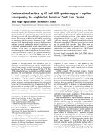
vertices (the same as a conventional linear tetrahedron). The function over TQ is defined by a quadratic polynomial. We call this element a linear-edge quadratic tetrahedron or quadratic tetrahedron. The quadratic polynomial is defined, in BernsteinB´ezier form, by ten coefficients cm , 0 ≤ m ≤ 9, as
TQ (u, v, w) =
1 2−k 2−k− j
∑∑ ∑
ci jk B2i jk (u, v, w)
(2)
k=0 j=0 i=0
The Bernstein-B´ezier basis functions B2i jk (u, v, w) are
B2i jk =
2!
(2 − i − j − k)!i! j!k!
(1 − u − v − w)2−i− j−k ui v j wk
(3)
6
B.F. Gregorski et al.
Fig. 1. Indexing of vertices and parameter space configuration for the ten control points of a
quadratic tetrahedron
The indexing of the coefficients is shown in Fig. 1.
4 Constructing a Quadratic Representation
A quadratic tetrahedron TQ is constructed from a linear tetrahedron TL with corner
vertices V0 ,V1 ,V2 , and V3 , by fitting quadratic functions along the six edges of TL .
Since a quadratic function requires three coefficients, there is an additional value
associated with each edge.
4.1 Fitting Quadratic Curves
Given a set of function values f0 , f1 . . . fn at positions x0 , x1 . . . xn , we create a
quadratic function that passes through the end points and approximates the remaining
data values.
The quadratic function C(t) we use to approximate the function values along an
edge is defined as
2
C(t) = ∑ ci B2i (t)
(4)
i=0
The quadratic Bernstein polynomial B2i (t) is defined as
B2i (t) =
2!
(1 − u)2−i ui
(2 − i)!i!
(5)
Adaptive Contouring with Quadratic Tetrahedra
7
First we parameterize the data by assigning parameter values t0 ,t1 . . .tn in the
interval [0, 1] to the positions x0 , x1 . . . xn . Parameter values are defined with a chordlength parameterization as
xi − x0
(6)
ti =
xn − x0
Next, we solve a least-squares approximation problem to determine the coefficients ci of C(t). The resulting overdetermined system of linear equations is
⎡ ⎤
⎤
(1 − t0 )2 2(1 − t0 )t0 t0 2 ⎡ ⎤
f0
⎢ f1 ⎥
⎢ (1 − t )2 2(1 − t )t t 2 ⎥ c0
1
1 1 1 ⎥
⎥
⎢
⎣ c1 ⎦ = ⎢
⎢ .. ⎥ .
⎢
..
..
.. ⎥
⎣
⎦
⎦
⎣
.
.
.
.
c2
2
2
f
n
(1 − tn ) 2(1 − tn )tn tn
⎡
(7)
Constraining C(t), so that it interpolates the endpoint values, i.e. C(0) = f0 and
C(1) = fn , leads to the system
⎤
⎡
2(1 − t1 )t1
⎢ 2(1 − t2 )t2 ⎥
⎥
⎢
⎥ [c1 ] =
⎢
..
⎦
⎣
.
⎡
⎢
⎢
⎢
⎣
2(1 − tn−1 )tn−1
f1 − f0 (1 − t1 )2 − fnt1 2
f2 − f0 (1 − t2 )2 − fnt2 2
..
.
⎤
⎥
⎥
⎥
⎦
(8)
fn−1 − f0 (1 − tn−1 )2 − fntn−1 2
for the one degree of freedom c1 .
4.2 Approximating a Dataset
A quadratic approximation of a dataset is created by approximating the data values
along each edge in the tetrahedral mesh with a quadratic function as described in
Sect. 4.1. Each linear tetrahedron becomes a quadratic tetrahedron. The resulting
approximation is C1 -continuous within a tetrahedron and C0 -continuous on shared
faces and edges. The approximation error ea for a tetrahedron T is the maximum
difference between the quadratic approximation over T and all original data values
associated with points inside and on T ’s boundary.
In tetrahedral meshes created by longest-edge bisection, each edge E in the mesh,
except for the edges at the finest level of the mesh, is the split edge of a diamond D,
see [5], and is associated with a split vertex SV . The computed coefficient c1 for the
edge E is stored with the split vertex SV . The edges used for computing the quadratic
representation can be enumerated by recursively traversing the tetrahedral mesh and
examining the refinement edges. This process is illustrated for the 2D case in Fig. 2.
Since quadratic tetrahedra have three coefficients along each edge, the leaf level of a
8
B.F. Gregorski et al.
Fig. 2. Enumeration of edges for constructing quadratic approximation using longest-edge
bisection. Circles indicate original function values used to compute approximating quadratic
functions along each edge
Fig. 3. Top: leaf tetrahedra for a mesh with linear tetrahedra. Bottom: leaf tetrahedra for a
mesh with quadratic tetrahedra
mesh with quadratic tetrahedra is one level higher in the mesh than the leaf level for
linear tetrahedra, see Fig. 3.
In summary, we construct a quadratic approximation of a volume data set as
follows:
1. For each edge of the mesh hierarchy, approximate the data values along the edge
with a quadratic function that passes through the endpoints.
2. For each tetrahedron in the hierarchy, construct a quadratic tetrahedron from the
six quadratic functions along its edges.
3. Compute the approximation error ea for each tetrahedron.
5 Contouring Quadratic Tetrahedra
We use the method described in [21] to extract and represent isosurfaces of quadratic
tetrahedra. We summarize the main aspects of the method here. First, the intersection
of the isosurface is computed with each face of the quadratic tetrahedron forming
face-intersection curves. Next, the face-intersection curves are connected end-to-end
to form groups of curves that bound various portions of the isosurface inside the
tetrahedron, see Fig. 4. Finally, the face-intersection groups are “triangulated” with
rational-quadratic patches to represent the various portions of the isosurface inside
the quadratic tetrahedron.
Since intersections are conic sects. [14], the intersections between the isosurface
and the faces produce rational-quadratic curves. We define a rational-quadratic curve
Adaptive Contouring with Quadratic Tetrahedra
9
Fig. 4. Isosurface bounded by six face-intersection curves. Dark dots indicate endpoints of the
curves
Q(t) with control points pi and weights wi , 0 ≤ i ≤ 2, as
Q(t) =
∑2i=0 wi pi B2i (t)
∑2i=0 wi B2i (t)
(9)
By connecting the endpoints of the N face-intersection curves Q j (t), 0 ≤ j ≤ N − 1,
we construct M rational-quadratic patches Qk (u, v), 0 ≤ k ≤ M − 1, to represent the
surface. We define a rational-quadratic patch Q(u, v) with six control points pi j and
six weights wi j as
2− j
∑2j=0 ∑i=0 wi j pi j B2i j (u, v)
Q(u, v) =
(10)
2− j
∑2j=0 ∑i=0 wi j B2i j (u, v)
A patch Q(u, v) is constructed from two or three face-intersection curves by using
the control points of the curves as the control points for Q(u, v). Four or more faceintersection curves require the use of a “divide-and-conquer” method that results in
multiple patches, see [21].
6 Results
We have applied our algorithm to various volume datasets. The datasets are all bytevalued, and the quadratic coefficients along the edges are stored as signed shorts.
In all examples, the mesh is refined to approximate the original dataset, according
to the quadratic tetrahedra approximation, within a user specified error bound eu .
The resulting mesh consists of a set of quadratic tetrahedra which approximates the
dataset within eu . The isosurface, a set of quadratic bezier patches, is extracted from
10
B.F. Gregorski et al.
Table 1. Error values, number of quadratic tetrahedra used for approximation, and number of
quadratic patches extracted
Dataset
Buckyball
Buckyball
Buckyball
H-Atom
H-Atom
Size
2563
2563
2563
1283
1283
Error
2.0
1.3
0.7
1.23
0.57
Tets
8560
23604
86690
8172
20767
Patches
4609
10922
32662
3644
7397
this mesh. Table 1 summarizes the results. It shows the error value, the number of
quadratic tetrahedra needed to approximate the dataset to within the specified error
tolerance, and the number of quadratic patches extracted from the mesh.
As discussed in Sect. 4.2, the error value indicates the maximum difference between the quadratic representation and the actual function values at the data points.
On the boundaries, our quadratic representation is C0 continuous with respect to the
function value and discontinuous with respect to the gradient; thus the gradients used
for shading are discontinuous at patch boundaries. This fact leads to the creases seen
in the contours extracted from the quadratic elements. The patches which define the
contour are tessellated and rendered as triangle face lists. A feature of the quadratic
representation is the ability to vary both the patch tessellation factor and the resolution of the underlying tetrahedral grid. This gives an extra degree of freedom with
which to balance isosurface quality and rendering speed.
The storage requirements of the linear and quadratic representations are summarized in Table 2. Storage costs of linear and quadratic representations with and without precomputed gradients are shown. When gradients are precomputed for shading,
a gradient must be computed at each data location regardless of representation. When
rendering linear surfaces, gradients are often precomputed and quantized to avoid the
cost of computing them at runtime. For quadratic patches, gradients do not need to
be precomputed because they can be computed from the analytical definition of the
surface. However, if gradients are precomputed, they can be used directly.
Table 2. Storage requirements(bytes) for linear and quadratic representations for a dataset
with 23n points. The linear representation consists of L = 23n diamonds, and the quadratic
representation consists of L8 = 23(n−1) diamonds. R is the number of bytes used to store the
error, min, and max values of a diamond, G is the number of bytes used to store a gradient,
and C is the number of bytes used to store a quadratic coefficient
Type Data Gradients B´ezier Coeffs Error/Min/Max
Total
Linear
L
0
0
RL
L(1 + R)
Linear
L
GL
0
RL
L(1 + G + R)
Quadratic L8
0
CL
R L8
L 1+8C+R
8
L
L
1+8G+8C+R
Quadratic 8
GL
CL
R8
L
8
Adaptive Contouring with Quadratic Tetrahedra
11
The difference between the leaf levels of linear and quadratic representations, as
described in Sect. 4.2, implies that there are eight times as many diamonds in the
linear representation than there are in the quadratic representation. We represent the
quadratic coefficients with two bytes. The quadratic coefficients for the Buckyball
dataset shown in Figs. 5 and 6 lie in the range [−88,390]. The representation of
error, min, and max values is the same for both representations. They can be stored
as raw values or compressed to reduce storage costs. The quadratic representation
essentially removes three levels from the binary tree of the tetrahedral mesh reducing
the number of error, min, and max values by a factor of eight compared with the
linear representation.
Fig. 5. Left: Isosurface of quadratic patches extracted using quadratic tetrahedra. Middle: Full
resolution isosurface (1798644 triangles). Right: Isosurface of triangles extracted from the
same mesh used to show the resolution of the tetrahedral grid. Isovalue = 184.4, Error = 0.7
Fig. 6. Isosurfaces extracted using quadratic tetrahedra at different error bounds. Top to Bottom: Error = 0.7, 1.2, and 2.0. Number of Quadratic Patches = 32662, 10922, 4609
The first dataset is a Buckyball dataset made from Gaussian functions. Figure 5
compares contours extracted using quadratic and linear tetrahedra against the full resolution surface. The isosurfaces are extracted from the same mesh which consists of
86690 tets; it yields 32662 quadratic patches. Figure 6 shows three isosurfaces of the
Buckyball from the same viewpoint at different resolutions. The images are created
by refining the mesh using a view-dependent error bound. Thus, the middle image,
for an error of 1.3 has more refinement in the region closer to the viewpoint and less
refinement in the regions further from the viewpoint. For the Buckyball dataset, the
12
B.F. Gregorski et al.
Fig. 7. Isosurface through the Hydrogen Atom dataset. The isosurface rendered using
quadratic patches, and the tetrahedra from which the contours were extracted. Isovalue = 9.4,
Error = 1.23, Number of patches = 3644
patches are tessellated with 28 vertices and 36 triangles. These images show how the
quadratic representation can be effectively used to adaptively approximate a dataset.
The second dataset is the Hydrogen Atom dataset obtained from www.volvis.org.
The dataset is the result of a simulation of the spatial probability distribution of the
electron in a hydrogen atom, residing in a strong magnetic field. Figure 7 shows
the surfaces generated from the quadratic tetrahedra and the coarse tetrahedral mesh
from which the contours are extracted.
Figure 8 is a closeup view of the dataset’s interior. It shows a thin “hourglasslike” feature emanating from the probability lobe visible on the right. For the Hydrogen Atom dataset, the patches are tessellated with 15 vertices and 16 triangles.
The isosurface extracted from the quadratic representation is compared with the the
linear isosurface to shown how the quadratic representation accurately approximates
the silhouette edges with a small number of elements.
Fig. 8. Closeup view of hydrogen atom dataset rendered with quadratic patches(left). As in Fig.
5, the isosurface extracted using linear elements(right) shows the resolution of the underlying
tetrahedral grid. Isovalue = 9.4, Error = 0.566
Adaptive Contouring with Quadratic Tetrahedra
13
7 Conclusions
We have presented an algorithm for approximating and contouring datasets with
quadratic tetrahedra. Our algorithm uses hierarchically defined tetrahedral meshes
to construct a multiresolution representation. This representation is used to approximate the dataset within a user specified error tolerance. Quadratic tetrahedra are created from this multiresolution mesh by constructing approximating quadratic functions along edges and using these functions to form quadratic tetrahedra. We have
improved previous methods for visualizing quadratic elements by showing how to
directly contour them without splitting them into a large number of linear elements.
Comparisons of the storage costs of quadratic and linear representations show that
quadratic elements can represent datasets with a smaller number of elements and
without a large storage overhead.
Future work is planned in these areas:
• Improving the quality and speed of the contour extraction and comparing
the quality of the surfaces to those generated from linear tetrahedra. Currently, our algorithm generates some small thin surfaces that are undesirable for
visualization. Additionally we are working on arbitrary slicing and volume rendering of quadratic elements.
• Improving the computation of the quadratic representation. Our current algorithm, while computationally efficient, fails to capture the behavior of the
dataset within a tetrahedron, and yields discontinuous gradients at the boundaries. It is desirable to have an approximation that is overall C1 -continuous or
C1 -continuous in most regions and C0 in regions where discontinuities exist in
the data. A C1 -continuous approximation might improve the overall approximation quality, allowing us to use fewer elements, and would improve the visual
quality of the extracted contours.
Acknowledgments
This work was performed under the auspices of the U.S. Department of Energy by
University of California Lawrence Livermore National Laboratory under contract
No. W-7405-Eng-48. This work was also supported by the National Science Foundation under contracts ACI 9624034 (CAREER Award), through the Large Scientific and Software Data Set Visualization (LSSDSV) program under contract ACI
9982251, through the National Partnership for Advanced Computational Infrastructure (NPACI) and a large Information Technology Research (ITR) grant; the National
Institutes of Health under contract P20 MH60975-06A2, funded by the National Institute of Mental Health and the National Science Foundation; and the Lawrence Livermore National Laboratory under ASCI ASAP Level-2 memorandum agreement
B347878, and agreements B503159 and B523294; We thank the members of the
Visualization and Graphics Research Group at the Institute for Data Analysis and
Visualization (IDAV) at the University of California, Davis.
14
B.F. Gregorski et al.
References
1. B.K. Bloomquist, Contouring Trivariate Surfaces, Masters Thesis, Arizona State University, Computer Science Department, 1990
2. P. Cignoni and P. Marino and C. Montani and E. Puppo and R. Scopigno Speeding Up
Isosurface Extraction Using Interval Trees IEEE Transactions on Visualization and Computer Graphics 1991, 158–170
3. P. J. Davis Interpolation and Approximation Dover Publications, Inc., New York, NY. 2,
3
4. Klaus Engel and Rudiger Westermann and Thomas Ertl Isosurface Extraction Techniques
For Web-Based Volume Visualization Proceedings of IEEE Visualization 1999, 139–146
5. Benjamin Gregorski, Mark Duchaineau, Peter Lindstrom, Valerio Pascucci, and Kenneth
I. Joy Interactive View-Dependent Extraction of Large Isosurfaces Proceedings of IEEE
Visualization 2002, 475–482
6. T. Gerstner Fast Multiresolution Extraction Of Multiple Transparent Isosurfaces, Data
Visualization 2001 Proceedings of VisSim 2001
7. Thomas Gerstner and Renato Pajarola, Topology Preserving And Controlled Topology
Simplifying Multiresolution Isosurface Extraction, Proceedings of IEEE Visualization
2000, 259–266
8. T. Gerstner and M. Rumpf, Multiresolution Parallel Isosurface Extraction Based On
Tetrahedral Bisection, Volume Graphics 2000, 267–278
9. Leif P. Kobbelt, Mario Botsch, Ulrich Schwanecke, and Hans-Peter Seidel FeatureSensitive Surface Extraction From Volume Data SIGGRAPH 2001 Conference Proceedings, 57–66
10. Y. Livnat and C. Hansen View Dependent Isosurface Extraction Proceedings of IEEE
Visualization 1998, 172–180
11. Tao Ju, Frank Losasso, Scott Schaefer, and Joe Warren Dual contouring of hermite data
SIGGRAPH 2002 Conference Proceedings, 339–346
12. Jian Huang, Yan Li, Roger Crawfis, Shao-Chiung Lu, and Shuh-Yuan Liou A Complete
Distance Field Representation Proceedings of Visualization 2001, 247–254
13. Gerald Farin, Curves and Surfaces for CAGD, Fifth edition, Morgan Kaufmann Publishers Inc., San Francisco, CA, 2001
14. A.J. Worsey and G. Farin, Contouring a bivariate quadratic polynomial over a triangle,
Computer Aided Geometric Design 7 (1–4), 337–352, 1990
15. B. Hamann, I.J. Trotts, and G. Farin On Approximating Contours of the Piecewise Trilinear Interpolant using triangular rational-quadratic B´ezier patches, IEEE Transactions
on Visualization and Computer Graphics, 3(3), 315–337 1997
16. Tom Roxborough and Gregory M. Nielson, Tetrahedron Based, Least Squares, Progressive Volume Models With Application To Freehand Ultrasound Data”, In Proceedings of
IEEE Visualization 2000, 93–100
17. S. Marlow and M.J.D. Powell, A Fortran subroutine for plotting the part of a conic that
is inside a given triangle, Report no. R 8336, Atomic Energy Research Establishment,
Harwell, United Kingdom, 1976
18. R. Van Uitert, D. Weinstein, C.R. Johnson, and L. Zhukov Finite Element EEG and MEG
Simulations for Realistic Head Models: Quadratic vs. Linear Approximations Special
Issue of the Journal of Biomedizinische Technik, Vol. 46, 32–34, 2001.
19. David F. Wiley, H.R. Childs, Bernd Hamann, Kenneth I. Joy, and Nelson Max, Using
Quadratic Simplicial Elements for Hierarchical Approximation and Visualization, Visualization and Data Analysis 2002, Proceedings, SPIE - The International Society for
Optical Engineering, 32–43, 2002
Adaptive Contouring with Quadratic Tetrahedra
15
20. David F. Wiley, H.R. Childs, Bernd Hamann, Kenneth I. Joy, and Nelson Max, Best
Quadratic Spline Approximation for Hierarchical Visualization, Data Visualization 2002,
Proceedings of VisSym 2002
21. D. F. Wiley, H. R. Childs, B. F. Gregorski, B. Hamann, and K. I. Joy Contouring Curved
Quadratic Elements Data Visualization 2003, Proceedings of VisSym 2003
22. Jane Wilhelms and Allen Van Gelder Octrees for Faster Isosurface Generation ACM
Transaction in Graphics, 201–227, July 1992
On the Convexification of Unstructured Grids
from a Scientific Visualization Perspective
Jo˜ao L.D. Comba1 , Joseph S.B. Mitchell2 , and Cl´audio T. Silva3
1
2
3
Federal University of Rio Grande do Sul (UFRGS)
Stony Brook University
University of Utah
Summary. Unstructured grids are extensively used in modern computational solvers and,
thus, play an important role in scientific visualization. They come in many different types.
One of the most general types are non-convex meshes, which may contain voids and cavities.
The lack of convexity presents a problem for several algorithms, often causing performance
issues.
One way around the complexity of non-convex methods is to convert them into convex
ones for visualization purposes. This idea was originally proposed by Peter Williams in his
seminal paper on visibility ordering. He proposed to fill the volume between the convex hull
of the original mesh, and its boundary with “imaginary” cells. In his paper, he sketches two
algorithms for potentially performing this operation, but stops short of implementing them.
This paper discusses the convexification problem and surveys the relevant literature. We
hope it is useful for researchers interested in the visualization of unstructured grids.
1 Introduction
The most common input data type in Volume Visualization is a regular (Cartesian)
grid of voxels. Given a general scalar field in ℜ3 , one can use a regular grid of voxels
to represent the field by regularly sampling the function at grid points (λ i, λ j, λ k),
for integers i, j, k, and some scale factor λ ∈ ℜ, thereby creating a regular grid of
voxels. However, a serious drawback of this approach arises when the scalar field
is disparate, having nonuniform resolution with some large regions of space having
very little field variation, and other very small regions of space having very high
field variation. In such cases, which often arise in computational fluid dynamics and
partial differential equation solvers, the use of a regular grid is infeasible since the
voxel size must be small enough to model the smallest “features” in the field. Instead,
irregular grids (or meshes), having cells that are not necessarily uniform cubes, have
been proposed as an effective means of representing disparate field data.
18
Jo˜ao L.D. Comba et al.
Irregular-grid data comes in several different formats [37]. One very common
format has been curvilinear grids, which are structured grids in computational space
that have been “warped” in physical space, while preserving the same topological
structure (connectivity) of a regular grid. However, with the introduction of new
methods for generating higher quality adaptive meshes, it is becoming increasingly
common to consider more general unstructured (non-curvilinear) irregular grids, in
which there is no implicit connectivity information. Furthermore, in some applications disconnected grids arise.
Preliminaries
We begin with some basic definitions. A polyhedron is a closed subset of ℜ3 whose
boundary consists of a finite collection of convex polygons (2-faces, or facets) whose
union is a connected 2-manifold. The edges (1-faces) and vertices (0-faces) of a
polyhedron are simply the edges and vertices of the polygonal facets. A bounded
convex polyhedron is called a polytope. A polytope having exactly four vertices (and
four triangular facets) is called a simplex (tetrahedron). A finite set S of polyhedra
forms a mesh (or an unstructured grid) if the intersection of any two polyhedra from S
is either empty, a single common vertex, a single common edge, or a single common
facet of the two polyhedra; such a set S is said to form a cell complex. The polyhedra
of a mesh are referred to as the cells (or 3-faces). We say that cell C is adjacent to
cell C if C and C share a common facet. The adjacency relation is a binary relation
on elements of S that defines an adjacency graph.
A facet that is incident on only one cell is called a boundary facet. A boundary
cell is any cell having a boundary facet. The union of all boundary facets is the
boundary of the mesh. If the boundary of a mesh S is also the boundary of the convex
hull of S, then S is called a convex mesh; otherwise, it is called a non-convex mesh.
If the cells are all simplicies, then we say that the mesh is simplicial.
The input to our problem will be a given mesh S. We let c denote the number of
connected components of S. If c = 1, the mesh is connected; otherwise, the mesh is
disconnected. We let n denote the total number of edges of all polyhedral cells in the
mesh. Then, there are O(n) vertices, edges, facets, and cells.
We use a coordinate system in which the viewing direction is in the −z direction,
and the image plane is the (x, y) plane. We let ρu denote the ray from the viewpoint
v through the point u.
We say that cells C and C are immediate neighbors with respect to viewpoint
v if there exists a ray ρ from v that intersects C and C , and no other cell C ∈
S has a nonempty intersection C ∩ ρ that appears in between the segments C ∩ ρ
and C ∩ ρ along ρ . Note that if C and C are adjacent, then they are necessarily
immediate neighbors with respect to very viewpoint v not in the plane of the shared
facet. Further, in a convex mesh, the only pairs of cells that are immediate neighbors
are those that are adjacent.
A visibility ordering (or depth ordering),
partially or completely, then C precedes C in the ordering: C
On the Convexification of Unstructured Grids
19
ordering is a linear extension of the binary behind relation, “<”, in which cell C
is behind cell C (written C < C ) if and only if C and C are immediate neighbors
and C at least partially obstructs C; i.e., if and only if there exists a ray ρ from
/ ρ ∩ C = 0,
/ ρ ∩ C appears in between v and
the viewpoint v such that ρ ∩ C = 0,
ρ ∩C along ρ , and no other cell C intersects ρ at a point between ρ ∩C and ρ ∩C .
A visibility ordering can be obtained in linear time (by topological sorting) from
the behind relation, (S, <), provided that the directed graph on the set of nodes S
defined by (S, <) is acyclic. If the behind relation induces a directed cycle, then
no visibility ordering exists. Certain types of meshes, (e.g., Delaunay triangulations
[16]) are known to have a visibility ordering from any viewpoint, i.e., they do not
have cycles, and thus can be called acyclic meshes.
Spatial Decompositions
There is a rich literature in the computational geometry community on spatial decompositions. See Nielson, Hagen and M¨uller [25] for an overview of their importance
in the context of visualization applications.
Spatial decomposition is an essential tool in finite element analysis and geometric
modeling. Applications require high-quality mesh generation, in which the goal is to
triangulate domains with elements that are “nice” in some well-defined sense (e.g.,
triangulations having no large angle [3]). See the recent surveys of Bern and Eppstein [4], Bern and Plassmann [5], and Bern [2], and the book of Edelsbrunner [16],
for a comprehensive overview of the literature.
A problem extensively studied in the early years of computational geometry was
the polygon triangulation problem, in which the goal was to decompose a simple
polygon, or a polygon with holes, into triangles. A milestone result in two-dimensional triangulations was the discovery by Chazelle [6] of a linear-time algorithm for
triangulating a simple polygon. Optimization problems related to decompositions of
polygons into convex pieces have been studied in many variations; see Chazelle and
Dobkin [7] and the survey of Keil [21].
In three or more dimensions, decomposition of polyhedral domains into “triangles” (tetrahedra) is substantially more complex. Ruppert and Seidel [27] have shown
that it is NP-complete to decide if a (non-convex) polyhedron can be tetrahedralized
without the addition of Steiner points. Chazelle and Palios [10] show that a (nonconvex) polyhedron having n vertices and r reflex edges can always be triangulated
(with the addition of Steiner points) in time O(nr + r2 log r) using O(n + r2 ) tetrahedra (which is worst-case optimal, since some polyhedra require Ω (n + r2 ) tetrahedra
in any triangulation).
A regular triangulation in dimension d is the vertical projection of the “lower”
side of a convex polytope in one higher dimension. The most widely studied regular
triangulation is the Delaunay triangulation of a point set, which is the projection
of the downward-facing facets of the convex hull of the lifted images of the input
points onto the paraboloid in one higher dimension. An alternative characterization
of a Delaunay triangulation is that the (hyper)sphere determined by the vertices of
each triangle (simplex) of a Delaunay triangulation is “site-free,” not containing input
20
Jo˜ao L.D. Comba et al.
points in its interior. See Edelsbrunner [15], as well as the book of Okabe, Boots, and
Sugihara [26] and the recent survey articles of Fortune [17]
Chazelle et al. [8] have examined how selectively adding points to an input
set in three dimensions results in the worst-case size of the Delaunay triangulation
being provably subquadratic in the input size, even though the worst-case size of a
Delaunay triangulation of n points in space is Θ (n2 ).
The meshes we study here are decompositions of polyhedral domains and piecewise-linear complexes, in which the decomposition is required to respect the facets
of the input. A constrained Delaunay triangulation is a variation of a Delaunay triangulation that is constrained to respect the input shape, while being, in
some sense, “as Delaunay as possible.” Such decompositions have desirable properties, favoring more regular tetrahedra over “skinny” tetrahedra. This makes them
particularly appealing for interpolation, visualization, and finite element methods.
Two-dimensional constrained Delaunay triangulations have been studied by, e.g.,
Chew [11], De Floriani and Puppo [14], and Seidel [29]. More recently, threedimensional constrained Delaunay triangulations have been studied for their use in
mesh generation; see the surveys mentioned above [2, 4, 5, 16], as well as Weatherill and Hassan [39]. Shewchuk [30–34] has developed efficient methods for threedimensional constrained Delaunay triangulations, including, most recently [34],
provable techniques of inserting constraints and performing “flips” (local modifications to the mesh) to construct constrained Delaunay and regular triangulations
incrementally.
Exploiting Mesh Properties
Meshes that conform to properties such as “convexity” and “acyclicity” are quite special, since they simplify the algorithms that work with them. Here are three instances
of visualization algorithms that exploit different properties of meshes:
• A classic technique for hardware-based rendering of unstructured meshes couples the Shirley-Tuchman technique for rendering a single tetrahedron [35] with
Williams’ MPVO cell-sorting algorithm [41]. For the case of acyclic convex
meshes, this is a powerful combination that leads to a linear-time algorithm
that is provably correct, i.e., one is guaranteed to get the right picture.1 When
the mesh is not convex or contains cycles, MPVO requires modifications that
complicate the algorithm and its implementation and lead to slower rendering
times [13, 22, 36].
• A recent hardware-based ray casting technique for unstructured grids has been
proposed by Weiler et al [40]. This is essentially a hardware-based implementation of the algorithm of Garrity [19]. Strictly speaking, this technique only works
for convex meshes. Due to the constraints of the hardware, instead of modifying the rendering algorithm, the authors employ a process of “convexification”,
originally proposed by Williams [41], to handle general cells.
1 The
rendering technique of Shirley and Tuchman [35] requires certain modifications as
proposed in Stein et al [38].