Controller-Design-for-Robot-Arm
Bạn đang xem bản rút gọn của tài liệu. Xem và tải ngay bản đầy đủ của tài liệu tại đây (4.48 MB, 139 trang )
A LMA M ATER S TUDIORUM - U NIVERSIT A`
DEGLI
S TUDI
DI
B OLOGNA
D IPARTIMENTO DI E LETTRONICA I NFORMATICA E S ISTEMISTICA
D OTTORATO DI R ICERCA IN AUTOMATICA
E R ICERCA O PERATIVA - ING/INF-04
XIX C ICLO
P H .D. T HESIS
Model and Control of Tendon Actuated Robots
Gianluca Palli
C OORDINATORE
T UTOR
Prof. Claudio Melchiorri
Prof. Claudio Melchiorri
A.A. 2004/2006
Author’s Web Page: />Author’s e-mail:
Author’s address:
Dipartimento di Elettronica Informatica e Sistemistica
Alma Mater Studiorum - Universit`a degli Studi di Bologna
Viale Risorgimento 2
40136 Bologna
Italia
This thesis was written in LATEX 2ε on a Debian GNU/Linux system with GNU Emacs.
Copyright c 2007 by Gianluca Palli. All right reserved.
No part of this publication may be reproduced or transmitted in any form or by any means,
electronic or mechamical, including photocopy, recording or any information storage and
retrieval system, without permission in writing from the author.
To my wife Sonia
Abstract
The use of tendons for the transmission of the forces and the movements in robotic devices has been investigated from several researchers all over the world. The interest in
this kind of actuation modality is based on the possibility of optimizing the position of
the actuators with respect to the moving part of the robot, in the reduced weight, high reliability, simplicity in the mechanic design and, finally, in the reduced cost of the resulting
kinematic chain.
After a brief discussion about the benefits that the use of tendons can introduce in
the motion control of a robotic device, the design and control aspects of the UB Hand 3
anthropomorphic robotic hand are presented. In particular, the tendon-sheaths transmission system adopted in the UB Hand 3 is analyzed and the problem of force control and
friction compensation is taken into account.
The implementation of a tendon based antagonistic actuated robotic arm is then investigated. With this kind of actuation modality, and by using transmission elements with
nonlinear force/compression characteristic, it is possible to achieve simultaneous stiffness
and position control, improving in this way the safety of the device during the operation
in unknown environments and in the case of interaction with other robots or with humans.
The problem of modeling and control of this type of robotic devices is then considered
and the stability analysis of proposed controller is reported.
At the end, some tools for the realtime simulation of dynamic systems are presented.
This realtime simulation environment has been developed with the aim of improving the
reliability of the realtime control applications both for rapid prototyping of controllers
and as teaching tools for the automatic control courses.
Acknowledgments
The author thanks the Department of Electronics, Computer Science and Systems (DEIS)
of the Faculty of Engineer of the University of Bologna for the received support, the staff
of the Laboratory of Automation and Robotics (LAR) and the staff of the Institute of
Robotics and Mechatronics of the German Aerospace Center (DLR) for the help in the
experimental parts of the thesis.
A special thank to professor Claudio Melchiorri, the author is grateful to him for the
patience and the encouragement shown during these years.
Contents
1
Introduction
2
The UB Hand 3 Project
2.1 Introduction . . . . . . . . . . . . . . . .
2.2 Architecture and Kinematics of the Hand
2.2.1 Mechanical Structure of the Hand
2.2.2 Finger Kinematics . . . . . . . .
2.2.3 Configuration of the Tendons . . .
2.3 Finger Control . . . . . . . . . . . . . . .
2.4 Sensory Apparatus . . . . . . . . . . . .
2.5 Actuation Module . . . . . . . . . . . . .
2.6 The UB Hand 3 Realtime Control System
2.7 Experimental Activities . . . . . . . . . .
2.8 Conclusions . . . . . . . . . . . . . . . .
3
4
1
.
.
.
.
.
.
.
.
.
.
.
.
.
.
.
.
.
.
.
.
.
.
.
.
.
.
.
.
.
.
.
.
.
.
.
.
.
.
.
.
.
.
.
.
.
.
.
.
.
.
.
.
.
.
.
.
.
.
.
.
.
.
.
.
.
.
.
.
.
.
.
.
.
.
.
.
.
.
.
.
.
.
.
.
.
.
.
.
.
.
.
.
.
.
.
.
.
.
.
5
5
7
7
9
11
13
14
16
17
20
22
Model and Control of Tendon-Sheath Transmission Systems
3.1 Introduction . . . . . . . . . . . . . . . . . . . . . . . . .
3.2 Tendon-Sheath Transmission Characteristic . . . . . . . .
3.3 Tendon Dynamic Model . . . . . . . . . . . . . . . . . .
3.4 Experimental Results . . . . . . . . . . . . . . . . . . . .
3.5 The ‘Three-Mass’ Model . . . . . . . . . . . . . . . . . .
3.5.1 Validation of the Three-Mass Model . . . . . . . .
3.5.2 Geometric Properties of the Model . . . . . . . . .
3.6 Tendon Transmission Control . . . . . . . . . . . . . . . .
3.6.1 Friction Compensation . . . . . . . . . . . . . . .
3.6.2 Optimal Controller Design . . . . . . . . . . . . .
3.7 Conclusions . . . . . . . . . . . . . . . . . . . . . . . . .
.
.
.
.
.
.
.
.
.
.
.
.
.
.
.
.
.
.
.
.
.
.
.
.
.
.
.
.
.
.
.
.
.
.
.
.
.
.
.
.
.
.
.
.
.
.
.
.
.
.
.
.
.
.
.
.
.
.
.
.
.
.
.
.
.
.
.
.
.
.
.
.
.
.
.
.
.
.
.
.
.
.
.
.
.
.
.
.
25
25
26
29
31
32
34
35
37
38
39
41
.
.
.
.
.
.
.
.
43
43
44
47
49
50
51
52
53
.
.
.
.
.
.
.
.
.
.
.
.
.
.
.
.
.
.
.
.
.
.
.
.
.
.
.
.
.
.
.
.
.
.
.
.
.
.
.
.
.
.
.
.
.
.
.
.
.
.
.
.
.
.
.
.
.
.
.
.
.
.
.
.
.
.
.
.
.
.
.
.
.
.
.
.
.
.
.
.
.
.
.
.
.
.
.
.
Antagonistic Actuated Robots
4.1 Introduction . . . . . . . . . . . . . . . . . . . . . . . . . . . .
4.2 Dynamic Model of Robots with Antagonistic Actuated Joints . .
4.3 Static Feedback Linearization . . . . . . . . . . . . . . . . . . .
4.4 Control Strategy . . . . . . . . . . . . . . . . . . . . . . . . . .
4.5 Properties of the Transmission Elements . . . . . . . . . . . . .
4.5.1 Quadratic Force-Displacement Transmission Elements .
4.5.2 Exponential Force-Displacement Transmission Elements
4.6 Simulation of the Two-Link Antagonistic Actuated Arm . . . .
.
.
.
.
.
.
.
.
.
.
.
.
.
.
.
.
.
.
.
.
.
.
.
.
.
.
.
.
.
.
.
.
ii
Contents
4.7
Conclusions . . . . . . . . . . . . . . . . . . . . . . . . . . . . . . . . .
5 The DLR’s Antagonistic Actuated Joint
5.1 Introduction . . . . . . . . . . . . . . . . . . . . . . .
5.2 Characterization of the Transmission Elements . . . .
5.3 System Analysis . . . . . . . . . . . . . . . . . . . . .
5.3.1 Static Response . . . . . . . . . . . . . . . . .
5.3.2 Dynamic Response . . . . . . . . . . . . . . .
5.4 Actuator-Level Stiffness/Position Control . . . . . . .
5.4.1 Non-Backdrivable Actuators . . . . . . . . . .
5.4.2 Backdrivable Actuators . . . . . . . . . . . . .
5.5 Feedback Linearization . . . . . . . . . . . . . . . . .
5.5.1 Static Feedback Linearization . . . . . . . . .
5.5.2 Dynamic Feedback Linearization . . . . . . .
5.6 Identification of the Transmission Element Parameters
5.6.1 Offline Identification Procedure . . . . . . . .
5.6.2 Online Identification Algorithm . . . . . . . .
5.7 Conclusions . . . . . . . . . . . . . . . . . . . . . . .
.
.
.
.
.
.
.
.
.
.
.
.
.
.
.
.
.
.
.
.
.
.
.
.
.
.
.
.
.
.
.
.
.
.
.
.
.
.
.
.
.
.
.
.
.
.
.
.
.
.
.
.
.
.
.
.
.
.
.
.
.
.
.
.
.
.
.
.
.
.
.
.
.
.
.
.
.
.
.
.
.
.
.
.
.
.
.
.
.
.
.
.
.
.
.
.
.
.
.
.
.
.
.
.
.
.
.
.
.
.
.
.
.
.
.
.
.
.
.
.
.
.
.
.
.
.
.
.
.
.
.
.
.
.
.
.
.
.
.
.
.
.
.
.
.
.
.
.
.
.
6 Robots Feedback Linearization Control Based on Joint Position Measurements
6.1 Introduction . . . . . . . . . . . . . . . . . . . . . . . . . . . . . . . . .
6.2 Dynamics of Robotic Manipulators . . . . . . . . . . . . . . . . . . . . .
6.3 Feedback Linearization via Filtered Velocity . . . . . . . . . . . . . . . .
6.4 Stability of Feedback Linearization Based on Velocity Estimation . . . .
6.4.1 Lyapunov Function Candidate . . . . . . . . . . . . . . . . . . .
6.4.2 Time Derivative of the Lyapunov Function Candidate . . . . . . .
6.4.3 Comments . . . . . . . . . . . . . . . . . . . . . . . . . . . . .
6.5 Case Study . . . . . . . . . . . . . . . . . . . . . . . . . . . . . . . . .
6.6 Conclusions . . . . . . . . . . . . . . . . . . . . . . . . . . . . . . . . .
7 Realtime Simulation
7.1 Introduction . . . . . . . . . . . . . . . . . . . . . . . . . . .
7.2 Realtime Simulation of Dynamic Systems . . . . . . . . . . .
7.3 The COMEDI Realtime Simulation Driver . . . . . . . . . . .
7.4 The Inverted Pendulum . . . . . . . . . . . . . . . . . . . . .
7.4.1 The Control System . . . . . . . . . . . . . . . . . .
7.4.2 The COMEDI Driver of the Rotary Inverted Pendulum
7.4.3 Experimental Results . . . . . . . . . . . . . . . . . .
7.5 The Tendon-Sheath Lumped Parameter Model . . . . . . . . .
7.5.1 The Control System . . . . . . . . . . . . . . . . . .
7.5.2 The COMEDI Driver of the Tendon-Sheath System . .
7.5.3 Experimental Results . . . . . . . . . . . . . . . . . .
.
.
.
.
.
.
.
.
.
.
.
.
.
.
.
.
.
.
.
.
.
.
.
.
.
.
.
.
.
.
.
.
.
.
.
.
.
.
.
.
.
.
.
.
.
.
.
.
.
.
.
.
.
.
.
.
.
.
.
.
.
.
.
.
.
.
53
55
55
56
58
59
61
63
63
64
67
70
75
78
78
80
83
85
85
86
86
88
88
90
92
92
93
97
97
99
101
102
102
103
105
107
108
108
110
Contents
7.6
8
iii
Conclusions . . . . . . . . . . . . . . . . . . . . . . . . . . . . . . . . . 111
Conclusions
113
Bibliography
115
iv
Contents
List of Figures
2.1
2.2
2.3
2.4
2.5
2.6
2.7
2.8
2.9
2.10
2.11
2.12
2.13
2.14
2.15
2.16
2.17
2.18
2.19
2.20
2.21
2.22
3.1
3.2
3.3
3.4
3.5
3.6
3.7
Detail of the UB Hand 3 with the soft cover (a) and the UB Hand 3 in
comparison to the human hand (b). . . . . . . . . . . . . . . . . . . . . .
Structure of the finger module of the UB Hand 3. . . . . . . . . . . . . .
Adoption of coiled spring in elastic hinges. . . . . . . . . . . . . . . . .
The tendons path inside the finger. . . . . . . . . . . . . . . . . . . . . .
CAD design of the UB Hand 3 internal structure. . . . . . . . . . . . . .
Two degrees of freedom articulation of the upper fingers (a) and of the
thumb (b). . . . . . . . . . . . . . . . . . . . . . . . . . . . . . . . . . .
The experimental setup used for the identification of the kinematic properties of the finger. . . . . . . . . . . . . . . . . . . . . . . . . . . . . .
Rotational center of medial hinge. . . . . . . . . . . . . . . . . . . . . .
Static relation between tendon elongation and joint angle. . . . . . . . . .
Internal articulated finger structure. . . . . . . . . . . . . . . . . . . . .
Transformations from the cartesian space to the joints space and from the
joints space to the tendons space . . . . . . . . . . . . . . . . . . . . . .
Position sensor: FEM model (a) and actual implementation (b). . . . . . .
Output characteristic of the position sensor. . . . . . . . . . . . . . . . .
Tendon force sensor: FEM model (a), working principle (b). . . . . . . .
Output characteristic of a tendon tension sensor prototype with respect to
applied force and joint angle. . . . . . . . . . . . . . . . . . . . . . . . .
Instrumented actuation module. . . . . . . . . . . . . . . . . . . . . . . .
The UB Hand 3 (a) and the a detail of the forearm (b). . . . . . . . . . . .
The connection between UB Hand 3 and I/O card. . . . . . . . . . . . . .
The structure of the UB Hand 3 realtime control system. . . . . . . . . .
The communication of the realtime controller with the DAQ hardware and
the user. . . . . . . . . . . . . . . . . . . . . . . . . . . . . . . . . . . .
The UB Hand 3 grasping a bottle (a) and a cylindrical box (b). . . . . . .
Manipulation sequence of a pen. . . . . . . . . . . . . . . . . . . . . . .
Equilibrium of a tendon element. . . . . . . . . . . . . . . . . . . . . . .
The Dahl friction model. . . . . . . . . . . . . . . . . . . . . . . . . . .
Tendon tension distribution using the Coulomb friction model (a) and using the Dahl friction model (b). . . . . . . . . . . . . . . . . . . . . . . .
Lumped parameters tendon model. . . . . . . . . . . . . . . . . . . . . .
Simulation results: tendon tension input-output characteristic. . . . . . .
Simulation results: tendon tension distribution in the lumped parameters
model with sinusoidal input. . . . . . . . . . . . . . . . . . . . . . . . .
Acquisition system. . . . . . . . . . . . . . . . . . . . . . . . . . . . . .
5
7
7
8
9
9
10
10
11
12
13
15
15
16
16
17
18
19
20
21
21
22
27
28
29
29
30
31
32
vi
List of Figures
3.8
3.9
3.16
3.17
3.18
Experimental setup for the testing of the different materials. . . . . . . . .
Experiment results: transmission characteristic from constant bending angle (a) and constant tendon length (b). . . . . . . . . . . . . . . . . . . .
Experimental results: identification of friction parameters (a) and comparison between simulation and experimental results (b). . . . . . . . . .
Scheme of the three-mass tendon-sheath transmission model. . . . . . . .
Tendon tension input-output characteristic: comparison between the threemass and of the lumped parameters models (a) and comparison of simulation and experimental results for γ = π/2 (b). . . . . . . . . . . . . . .
Laboratory setup for the testing of the tendon tension controller. . . . . .
Setpoint, control action, tendon output tension (a) and tracking error (b). .
Setpoint, control action, output tension (a) and tracking error (b) with the
boundary layer. . . . . . . . . . . . . . . . . . . . . . . . . . . . . . . .
Response of the controller (3.26) with disturbance overestimation. . . . .
Scheme of the tendon tension optimal controller. . . . . . . . . . . . . .
Response of the optimal controller. . . . . . . . . . . . . . . . . . . . . .
37
39
40
41
4.1
4.2
4.3
4.4
A robotic arm with 3 antagonistic actuated joints. .
Detail of the antagonistic actuated joint. . . . . . .
(a) Joint positions and (b) trajectory tracking errors
(c) Joint stiffnesses and (d) stiffness tracking errors
.
.
.
.
45
52
54
54
5.1
5.2
5.3
5.4
56
57
60
5.5
5.6
5.7
5.8
5.9
5.10
5.11
5.12
5.13
The DLR’s antagonistic actuated joint. . . . . . . . . . . . . . . . . . . .
Detail (a) and working principle (b) of the transmission element. . . . . .
Scheme of the antagonistic actuated joint. . . . . . . . . . . . . . . . . .
Response of the antagonistic actuated joint to a step joint position variation for different values of the commanded stiffness. . . . . . . . . . . .
Response of the actuator level controller. . . . . . . . . . . . . . . . . . .
Response of actuator level controller with feedforward action. . . . . . .
Response of the actuator level controller with setpoint compensation. . . .
Response of the feedback linearization control. . . . . . . . . . . . . . .
Scheme of the offline identification experiment. . . . . . . . . . . . . . .
Offline estimation results. . . . . . . . . . . . . . . . . . . . . . . . . . .
Online identification algorithm. . . . . . . . . . . . . . . . . . . . . . . .
Online estimation results. . . . . . . . . . . . . . . . . . . . . . . . . . .
Online estimation results for a generic joint movement. . . . . . . . . . .
62
65
66
67
77
79
80
81
82
83
6.1
6.2
6.3
6.4
Positions and position errors of the two DOF robot. . . . . . . . . . . .
Velocity estimation errors. . . . . . . . . . . . . . . . . . . . . . . . .
Positions and position errors of the two DOF robot with D = diag{1, 1}.
Velocity estimation errors with D = diag{1, 1}. . . . . . . . . . . . . .
94
94
95
95
7.1
Left: typical software structure; Right: software structure with the COMEDI
library. . . . . . . . . . . . . . . . . . . . . . . . . . . . . . . . . . . . . 98
3.10
3.11
3.12
3.13
3.14
3.15
.
.
.
.
.
.
.
.
.
.
.
.
.
.
.
.
.
.
.
.
.
.
.
.
.
.
.
.
.
.
.
.
.
.
.
.
.
.
.
.
.
.
.
.
.
.
.
.
32
33
34
34
35
35
37
List of Figures
7.2
7.3
7.4
7.5
7.6
7.7
7.8
Flowchart of the realtime integration algorithm. . . . . . . . . . . . . . .
Rotary inverted pendulum. . . . . . . . . . . . . . . . . . . . . . . . . .
The rotary inverted pendulum is balanced. . . . . . . . . . . . . . . . . .
Comparison between the positions of the real and the realtime simulated
plant. . . . . . . . . . . . . . . . . . . . . . . . . . . . . . . . . . . . .
Difference of positions and comparison between the velocities of the real
and the realtime simulated plant. . . . . . . . . . . . . . . . . . . . . . .
Representation of the tendon-sheath lumped parameter model. . . . . . .
Comparison between Matlab/Simulink and the realtime environment. . .
vii
101
103
106
107
108
108
110
viii
List of Figures
List of Tables
2.1
Degrees of mobility for each fingers . . . . . . . . . . . . . . . . . . . .
12
5.1
5.2
Parameters of the DLR’s antagonistic actuated joint. . . . . . . . . . . .
Mean value of the transmission elements estimated parameters and their
percent errors. . . . . . . . . . . . . . . . . . . . . . . . . . . . . . . . .
Mean value of the transmission elements parameters estimated with the
online algorithm. . . . . . . . . . . . . . . . . . . . . . . . . . . . . . .
58
79
6.1
Parameters of the two DOF manipulator considered in the simulations. . . . . .
93
7.1
7.2
The parameters of the Quanser rotary inverted pendulum. . . . . . . . . . 104
The parameters of the tendon-sheath lumped parameter model. . . . . . . 109
5.3
82
x
List of Tables
1
Introduction
While tendons, or more in general cables, are widely used in many mechanical devices
since the 19th century, the use of tendons in robotic applications has been studied since
the early 80’s, and several tendon actuated robots have been developed all over the world,
both in research laboratories and in industries. Often, tendons are used in robotic hands
[1, 2, 3] and in parallel robots [4, 5, 6]. The main reasons of the interest in robotic
tendon applications are their efficiency in the transmission of the forces from remotely
located actuators to the moving parts of the robot, the reliability and the simplicity of
implementation of this kind of transmission system, and because they allow to reduce
the weight and the cost of the overall device. The main drawbacks of this transmission
modality are, first of all, the limitation to both the static and the dynamic performance
due to the non-negligible tendon elasticity and, depending also on the routing systems
that guide the tendons from the actuator to the joint, the distributed friction along the
tendon path and the necessity of maintaining a suitable tendon pretension to avoid the
cable slack.
In the human body, or, more in general, in the biologic organisms, the transmission
of the movements is realized by means of the muscles, that in many cases act as linear
actuators, connected to the articulations, the joints, through tendons. Moreover, in almost
all the articulations of the human body, more than one muscle-tendon couple works in
antagonistic configuration to realize the movement. This actuation structure gives to humans an optimal behavior both in the free space movements and during the interaction
with the external environment. On the base of these considerations, an increasing interest has been posed, in the last years, in the study and in the development of antagonistic
actuated robots, as a way to realize variable stiffness devices. Since at least two cooperating actuators must be used to adjust simultaneously both the position and the stiffness
of a single joint, the use of tendon transmission systems in antagonistic actuated robots
allows to optimize the mass distribution by placing the actuators remotely with respect to
the joints, while in other implementations both the actuators are placed near to the joint,
resulting in a considerable increment of the links inertia.
The starting point of my research activity has been the development of the UB Hand
1
3 , with particular attention for the design of both the sensory apparatus and the actuation
1 University
of Bologna Hand, version 3.
2
1. Introduction
system. As a consequence of the complexity of this kind of devices, due the number of
actuators and sensors involved, a great effort has been devoted also to the definition and
the development of the realtime control system of the UB Hand 3. After the evaluation
of the advantages and of the drawbacks of the particular implementation adopted, an
intensive study of the tendon-sheath transmission system of the UB Hand 3 has been
made to overcome the limitations to both the static and the dynamic performance of the
finger position and force control.
As a natural extension of this research activity, the application of tendons in antagonistic configuration together with transmission elements with nonlinear force/compression
characteristic has been studied. This actuation modality allows the simultaneous control
of both the position and the stiffness of robotic devices. The research on this topic has
been carried out during my stay at the German Aerospace Center (DLR) in Oberpfaffenhofen.
A great attention has been posed also in the development of tools for the programming and the testing of realtime control applications in the RTAI-Linux environment. A
software library for the realtime simulation of dynamic systems has been build and a live
Linux distribution has been realized to collect all the more useful tools for the RTAI control applications developer. This environment has been successfully used as teaching tool
in automatic control courses.
This thesis is organized as follow:
• In Chapter 2 the UB Hand 3 project is presented, and the more important features
of this device are discussed. The activities for the development of the purposely
designed sensors and actuators are reported and the structure of the control system of the UB Hand 3 is illustrated together with the preliminary activities for the
evaluation of the manipulation capabilities of this device.
• In Chapter 3 the tendon-sheath transmission system adopted in the UB Hand 3 is
investigated in deep with the aim of improving the performance of the system in the
control of the force that the tendons apply to the hinges. Suitable solutions for the
compensation of the friction and for the control of the output tension of the tendon
are proposed.
• The analysis on the dynamics of antagonistic actuated robots is presented in Chapter 4. The conditions that allow to achieve simultaneous stiffness and position
control of anthropomorphic robotic arms are discussed, taking into account the
characteristics of the transmission system adopted to drive the robot. The feedback linearization of the system is presented and the simulation results of a 2-link
manipulators are reported.
• The Chapter 5 presents the analysis of the antagonistic actuated joint implemented
at the DLR and the experimental activity carried out to evaluate the effectiveness of
the design approach for the realization of a variable stiffness device.
3
• Due to the fact that very often linear filters are used instead of state observers for the
estimation of the velocity from the joint position information, the stability analysis
of feedback linearization control of robotic manipulators based on filtered position
information is reported in Chapter 6.
• The development of realtime algorithms for the simulation of dynamic systems
is presented in Chapter 7. This approach allows to design and test the control
application using the simulated system, improving the safety of the tuning phase of
the controller and improving the reliability of the final control application.
• In Chapter 8 some conclusion about the overall work are reported together with
considerations about the open issues and plans for the future research activities.
4
1. Introduction
2
The UB Hand 3 Project
2.1 Introduction
In dexterous robotic hands the reproduction of human hand compliance during the interaction with the objects to be manipulated (as demonstrated in [7], [8], [9]) is fundamental
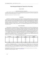
for grasp adaptability and stability. Furthermore, a continuous soft cover increases the
level of protection against external agents and unexpected impacts, thus increasing the
reliability of the robotic hand. Even if these advantages are widely recognized, few humanoid robotic hands, so far, have been designed specifically to optimize this aspect. In
most cases they are covered with thin layers of elastomeric material, capable to provide
high surface friction but not enough thick to actually work as real compliant pads. One of
the main reasons why it is so difficult to host pads with adequate thickness and therefore
deformability is the usual adoption of mechanical finger structures based prevalently on
the exoskeletal pattern, which means rigid hollow frames with transmissions or actuation
inside [10], [11].
(a)
(b)
Figure 2.1: Detail of the UB Hand 3 with the soft cover (a) and the UB Hand 3 in comparison to the human hand (b).
6
2. The UB Hand 3 Project
The UB Hand 3 project addresses alternative design solutions in order to substitute
the exoskeletal structure with an endoskeletal articulated frame with a tendon-based actuation, aiming to reach the desired external compliance and to simplify the overall mechanical complexity of the hand. The endoskeletal structures may be implemented successfully considering different morphologies of the joints: among the potential solutions,
biologically-inspired joints with rolling or sliding conjugated profiles or non biologicallyinspired solutions like compliant hinges to substitute articulations. The goals are to reduce the complexity of the articulated structure by reducing the number of components,
to reduce the effects of drawbacks like backlash or friction and to increase the reliability
of the mechanical structure. Moreover, the reconsideration of a tendon transmission for
remote actuation of joints is coherent with the perspective of hand-arm integration and
with a more generalized design of the finger structure, not conditioned by the type of the
actuators.
The general aim of the project is to test non-conventional design solutions, understanding what may be their advantages and their limits by means of theoretical investigation, practical implementation and testing as well. A strong issue is to test not only
the validity of such solutions in terms of theoretical behavior, but also to point out and
to evaluate technological aspects related to their application and their compatibility with
general specifications, like the adoption of proper sensory equipment or the application
of specific control strategies. One of the key choices of the UB Hand 3 project is to investigate advantages and limits of articulated structures obtained with serial compliant
mechanisms actuated by means of tendons: a series of different finger architectures have
been built and evaluated based on this concept and described in previous works [12], [13],
[14], [15].
This project has been, for my research activity, a starting point for the evaluation of
various problematics related to the modeling of compliant structures and the control of
tendon actuated systems, with particular attention for sheath-based tendon routing systems and to antagonistic actuation. Another important point of interest for me has been
the development of realtime control application for such a complex mechatronic device
like the UB Hand 3. The overall project has been developed thanks to the joined work
of the Department of Mechanical Engineering (DIEM) and Department of Electronics,
Computer Science and Systems (DEIS) of the University of Bologna.
This chapter illustrates the hand architecture that is the result of the evolution performed so far: it will probably be improved in the future, but it seems now a valid base to
start on-field evaluation of the proposed concepts. Some preliminary results of the hand
operating capability are presented in the final part of the chapter. They have been obtained
with a prototype that only partially implements all the prospected solutions, but already
confirm that the proposed approach exhibits very high potential.
2.2. Architecture and Kinematics of the Hand
External coating (skin)
Soft pad
7
Internal endoskeleton
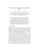
Figure 2.2: Structure of the finger module of the UB Hand 3.
2.2 Architecture and Kinematics of the Hand
Due to the particular actuation modality adopted in this robotic device, the kinematics of
each finger can be seen as the result of the combination both of its mechanical structure
and of the connection of the tendons to the actuators and perhaps to the coupling between
the movements of the different tendons that driver the finger. All these aspects, together
with the mechanical structure of the UB Hand 3, will be illustrated in this section.
2.2.1 Mechanical Structure of the Hand
The present prototype of the UB Hand 3 is characterized by a modular structure in which
four identical fingers and one opposable thumb are assembled on a carpal frame, that will
be connected to a wrist. The tendons are routed from the forearm, where the actuators are
placed, to the fingers passing trough the wrist and the carpal frame, miming in this way
the human hand configuration. A compliant layer, reproducing the role of human hand
soft tissues, covers the endoskeletal structure, as shown in Fig. 2.1(a) and sketched in Fig.
2.2 for a single finger. The overall dimensions of the hand are very similar to the human
one and in Fig. 2.1(b) a direct comparison is proposed.
The internal articulated structure is designed according the “compliant mechanism”
concept so that the mobility of the phalanges is obtained by means of elastic joints (the
(a)
(b)
Figure 2.3: Adoption of coiled spring in elastic hinges.