Commercial aircraft hydraulic systems
Bạn đang xem bản rút gọn của tài liệu. Xem và tải ngay bản đầy đủ của tài liệu tại đây (21.97 MB, 267 trang )
The development of the book was sponsored by
Shanghai Jiaotong University Press
Commercial Aircraft
Hydraulic Systems
Shanghai Jiao Tong University Press
Aerospace Series
Shaoping Wang
Department of Mechatronic Engineering
Beihang University, China
Mileta Tomovic
Batten College of Engineering and Technology
Old Dominion University, USA
Hong Liu
AVIC
The first Aircraft Institute
AMSTERDAM l BOSTON l HEIDELBERG l LONDON
NEW YORK l OXFORD l PARIS l SAN DIEGO
SAN FRANCISCO l SINGAPORE l SYDNEY l TOKYO
Academic Press is an imprint of Elsevier
Academic Press is an imprint of Elsevier
225 Wyman Street, Waltham, MA 02451, USA
The Boulevard, Langford Lane, Kidlington, Oxford OX5 1GB, UK
Copyright Ó 2016 Shanghai Jiao Tong University Press. Published by Elsevier Inc.
All rights reserved.
No part of this publication may be reproduced or transmitted in any form or by any means,
electronic or mechanical, including photocopying, recording, or any information storage and
retrieval system, without permission in writing from the publisher. Details on how to seek
permission, further information about the Publisher’s permissions policies and our
arrangements with organizations such as the Copyright Clearance Center and the Copyright
Licensing Agency, can be found at our website: www.elsevier.com/permissions.
This book and the individual contributions contained in it are protected under copyright by
the Publisher (other than as may be noted herein).
Notices
Knowledge and best practice in this field are constantly changing. As new research and
experience broaden our understanding, changes in research methods, professional practices,
or medical treatment may become necessary.
Practitioners and researchers must always rely on their own experience and knowledge in
evaluating and using any information, methods, compounds, or experiments described
herein. In using such information or methods they should be mindful of their own safety and
the safety of others, including parties for whom they have a professional responsibility.
To the fullest extent of the law, neither the Publisher nor the authors, contributors, or editors,
assume any liability for any injury and/or damage to persons or property as a matter of
products liability, negligence or otherwise, or from any use or operation of any methods,
products, instructions, or ideas contained in the material herein.
ISBN: 978-0-12-419972-9
British Library Cataloguing-in-Publication Data
A catalogue record for this book is available from the British Library
Library of Congress Cataloging-in-Publication Data
A catalog record for this book is available from the Library of Congress
For information on all Academic Press publications
visit our website at />
Typeset by TNQ Books and Journals
www.tnq.co.in
Printed and bound in the United States of America
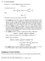
Foreword
In general, the flight control system is the critical system of an aircraft. The
aircraft hydraulic actuation system and its power supply system are very
important, related systems that directly influence aircraft flight performance
and flight safety. Over the past several decades, aircraft system design focused
predominantly on the design principle itself without considering the related
system effects. The hydraulic power supply system provides high-pressure
fluid to the actuation system; therefore, its characteristics and performance
could influence the actuation system performance. On the other hand, the
actuation system utilizes hydraulic power to drive the surfaces, the performance of which not only depends on the displacement control strategy but also
on the power supply performance. This book focuses on the aircraft flight
control system, including the interface between the hydraulic power supply
system and actuation system, and it provides the corresponding design principle and presents the latest research advances used in aircraft design.
The aircraft hydraulic system evolved with the flight control system.
Early flight control systems were purely mechanical systems in which the
pilot controlled the aircraft surfaces through mechanical lines and movable
hinge mechanisms. With the increase in aircraft velocity, the hinge moments
and required actuation forces increased significantly to the point at which
pilots had difficulty manipulating control surfaces. The hydraulic booster
appeared to give extra power to drive the surfaces. With the increasing
expansion of flight range and duration of flight, it became necessary to
develop and implement an automatic control system to improve the flight
performance and avoid pilot fatigue. Then, the electrically signaled (also
known as fly-by-wire (FBW)), hydraulic powered actuator emerged to drive
the aircraft control surfaces. Introduction of the FBW system greatly
improved aircraft flight performance. However, the use of many electrical
devices along with the flutter influence of the hydraulic servo actuation
system led to a reliability problem. This resulted in wide implementation of
redundancy technology to ensure high reliability of the FBW system.
Increasing the number of redundant channels will potentially increase degree
of fault. To achieve high reliability and maintainability, a monitoring and
fault diagnosis device is integrated in the redundant hydraulic power supply
system and redundant actuation system.
Modern aircraft design strives to increase the fuel economy and reduction
in environmental impacts; therefore, the high-pressure hydraulic power supply
ix
x Foreword
system, variable-pressure hydraulic system, and increasingly electrical system
are emerging to achieve the requirements of green flight.
This book consists of four chapters. Chapter 1 presents an overview of the
development of the hydraulic system for flight control along with the interface
between the flight control system and the hydraulic system. The chapter also
introduces different types of actuation systems and provides the requirements
of the flight control system for specification and design of the required hydraulic system. Chapter 2 introduces the basic structure of aircraft hydraulic
power supply systems, provides the design principle of the main hydraulic
components, and provides some typical hydraulic system constructions in
current commercial aircraft. Chapter 3 introduces the reliability design method
of electrical and mechanical components in the hydraulic system. The chapter
provides comprehensive reliability evaluation based on reliability, maintainability, and testability and gives the reliability evaluation of the aircraft
hydraulic power supply and actuation system. Chapter 4 introduces new
technologies used in modern aircraft, including the high-pressure hydraulic
power supply system, variable-pressure hydraulic power supply system, and
new types of hydraulic actuators.
We thank all of the committee members of a large aircraft flight control
series editorial board and all of the editors of Shanghai Jiaotong Press for their
help and assistance in successfully completing this book. The authors are also
grateful to Ms Hong Liu, Mr Zhenshui Li, and Mr Yisong Tian, who reviewed
the book outline and contributed to the writing of this book. We are indebted to
their comments. We should also mention that some of the general theory and
structure composition were drawn from related references in this book;
therefore, we would like to express our gratitude to their authors for providing
outstanding contributions in the related fields. Finally, we hope that the readers
will find the material presented in this book to be beneficial to their work.
Shaoping Wang
Mileta Tomovic
Hong Liu
July 2015
Preface
Aircraft design covers various disciplines, domains, and applications. Different
viewpoints have different related knowledge. The aircraft flight control series
focus on the fields that are related to the aircraft flight control system and
provide the design principle, corresponding technology, and some professional
techniques.
Commercial Aircraft Hydraulic Systems aims to provide the practical
knowledge of aircraft requirements for the hydraulic power supply system and
hydraulic actuation system; give the typical system structure and design principle; introduce some technology that can guarantee the system reliability,
maintainability, and safety; and discuss technologies used in current aircraft. The
intention is to provide a source of relevant information that will be of interest and
benefit to all of those people working in this area.
xi
Chapter 1
Requirements for the
Hydraulic System of a Flight
Control System
Chapter Outline
1.1 The Development of the
Hydraulic System Related
to the Flight Control System
1.2 The Interface between the
FCS and Hydraulic System
1
8
1.3 Actuation Systems
1.4 Requirement of the FCS
to the Hydraulic System
1.5 Conclusions
References
13
33
50
51
1.1 THE DEVELOPMENT OF THE HYDRAULIC SYSTEM
RELATED TO THE FLIGHT CONTROL SYSTEM [1]
The flight control system (FCS) is a mechanical/electrical system that transmits the control signal and drives the surface to realize the scheduled flight
according to the pilot’s command. FCSs include components required to
transmit flight control commands from the pilot or other sources to the
appropriate actuators, generating forces and torques. Flight control needs to
realize the control of aircraft flight path, altitude, airspeed, aerodynamic
configuration, ride, and structural modes. Because the performance of the FCS
directly influences aircraft performance and reliability, it can be considered as
one of the most important systems in an aircraft.
A conventional fixed-wing aircraft control system, shown in Figure 1.1,
consists of cockpit controls, connecting linkages, control surfaces, and the
necessary operating mechanisms to control an aircraft’s movement. The
cockpit controls include the control column and rudder pedal. The connecting
linkage includes a pushepull control rod system and cable/pulley system.
Flight control surfaces include the elevators, ailerons, and rudder. Flight
control includes the longitudinal, lateral-directional, lift, drag, and variable
geometry control system.
Since the first heavier-than-air aircraft was born, it is the pilot who drives
the corresponding surfaces through the mechanical system to control the
aircraft, which is called the manual flight control system (MFCS) without
Commercial Aircraft Hydraulic Systems. />Copyright © 2016 Shanghai Jiao Tong University Press. Published by Elsevier Inc. All rights reserved.
1
2
Commercial Aircraft Hydraulic Systems
FIGURE 1.1 Structure of the initial FCS.
power. A very early aircraft used a system of wing warping in which no
conventionally hinged control surfaces were used on the wing. A MFCS uses a
collection of mechanical parts such as pushrods, tension cables, pulleys,
counterweights, and sometimes chains to directly transmit the forces applied at
the cockpit controls to the control surfaces. Figure 1.1 shows the aircraft’s
purely mechanical manipulating system, in which a steel cable or rod is used
to drive the surfaces. If the pilot wants to move the flaps on a plane, then he
would pull the control column, which would physically pull the flaps in the
direction that the pilot desired. In this period, the designer focuses on the
friction, clearance, and elastic deformation of the transmission system so as to
achieve good performance.
With the increase of size, weight, and flight speed of aircraft, it became
increasingly difficult for a pilot to move the control surfaces against the
aerodynamic forces. The aircraft designers recognized that the additional
power sources are necessary to assist the pilot in controlling the aircraft.
The hydraulic booster, shown in Figure 1.2(a), appeared at the end of the
1940s, dividing the control surface forces between the pilot and the
boosting mechanism. The hydraulic booster utilizes the hydraulic power
with high pressure to drive the aircraft surfaces according to the pilot’s
command. As an auxiliary component, the hydraulic booster can increase
the force exerted on the aircraft surface instead of the pilot directly
changing the rotary or flaps. As the earliest hydraulic component that is
FIGURE 1.2 Evolution of the aircraft FCS. (a) Mechanical manipulating system with booster,
(b) irreversible booster control system, (c) reversible booster control system, (d) stability
augmentation control system, and (e) FBW systems [2].
4
Commercial Aircraft Hydraulic Systems
related to the aircraft FCS, the hydraulic booster changed the surface
maneuver from mechanical power to hydraulic power and resisted the hinge
moment of surfaces without the direct connection between the control rod
and surfaces. There are two kinds of hydraulic booster: reversible booster
and irreversible booster. In the case of the irreversible booster control
system shown in Figure 1.2(b), there is no direct connection between the
control rod and the surface. The pilot controls the hydraulic booster to
change the control surface without feeling of the flight state. The advantages of hydraulically powered control surfaces are that (aerodynamic load
on the control surfaces) drag is reduced and control surface effectiveness is
increased. Therefore, the reversible booster control system emerged through
installing the sensing device to provide the artificial force feeling to the
pilot, shown in Figure 1.2(c). The reversible booster control system
includes the spring, damper, and additional weight to provide the feedback
(feeling) so that a pilot could not pull too hard or too suddenly and damage
the aircraft. In this kind of aircraft, the characteristics of booster (maximum
output force, distance, and velocity) should satisfy the flight control
performance.
In general, the center of gravity is designed forward of center of lift for
positive stability. Modern fly-by-wire (FBW) aircraft is designed with a
relaxed stability design principle. This kind of design requires smaller surfaces
and forces, low trim loads, reduced aerodynamic airframe stability, and more
control loop augmentation. This kind of aircraft operates with augmentation
under subsonic speed. When the aircraft operates at supersonic speed, the
aircraft focus moves backward, and the longitudinal static stability torque
rapidly increases. At this time, it needs enough manipulating torque to meet
the requirements of aircraft maneuverability. However, the supersonic area in
the tail blocks the disturbance propagation forward, and the elevator control
effectiveness is greatly reduced. Hence, it is necessary to add signals from
stability augmentation systems and the autopilot to the basic manual control
circuit. As we know, a good aircraft should have good stability and good
maneuverability. The unstable aircraft is not easy to control. Because the
supersonic aircraft’s flight envelope expands, its aerodynamics are difficult to
meet the requirements at low-altitude/low-speed and high-altitude/high-speed.
In the high-altitude supersonic flight, the aircraft longitudinal static stability
dramatically increases whereas its inherent damping reduces, then the short
periodic oscillation in the longitudinal and transverse direction appear that
greatly influences the aircraft maneuverability. To maintain stability of the
supersonic aircraft, it is necessary to install the stability augmentation system
shown in Figure 1.2(d). Because the stability augmentation system can keep
the aircraft stable even in static instability design, the automatic flight control
system (AFCS) appeared. The AFCS consists of electrical, mechanical, and
Requirements for the Hydraulic System Chapter j 1
5
hydraulic components that generate and transmit automatic control commands
to the aircraft surfaces. Through measuring the perturbation from the gyroscope and accelerometer, the stability augmentation system generates the
artificial damping with the help of reverse surface motion to quickly reduce the
oscillation. The stability augmentation system provides good stability to the
aircraft at high altitudes, high speeds, and at a large angle of attack states. In
this kind of system, the stability augmentation is independent of the pilot
manipulating system. To safely manipulate the aircraft, the stability
augmentation and pilot manipulating system have different control limits of
authority. From the pilot’s point of view, the stability augmentation system is
the part of aircraft and the pilot controls the aircraft like an “equivalent
aircraft” with good control performance. Because the aircraft surface is
controlled both by control column command and by augmentation system
command, the control authority of augmentation system is just 3e6% of
control authority.
Although the stability augmentation system can improve aircraft stability,
it can also weaken the aircraft control response sensitivity to a certain extent,
which will reduce its maneuverability. To eliminate this drawback, the
control stability augmentation system emerges with the pilot’s command
based on the stability augmentation system shown in Figure 1.2(d). Through
adjustment of the pilot control and control stability augmentation, the
contradiction between stability and controllability can be solved to achieve
good aircraft maneuverability and flexibility. Because the pilot can directly
control the surface, the authority of augmentation can be increased to more
than 30% of control authority.
In this period, the hydraulic actuators were used to drive the surfaces,
which are powered by hydraulic pumps in the hydraulic circuit. The hydraulic
circuit consists of hydraulic pumps, reservoirs, filters, pipes, and actuators.
Hydraulic actuators convert hydraulic pressure into control surface
movements.
Although the hydromechanical control system can realize the control with
good stability and good maneuverability, it is difficult to realize fine
manipulation signal transmission because of the inherent friction, clearance,
and elastic deformation existing in the mechanical system. The following are
common disadvantages for traditional mechanical systems or systems with
augmentation:
1. The mechanical transmission and control system is big and heavy.
2. It has inherent nonlinear factors such as friction, clearance, and natural
vibration due to hysteresis.
3. The mechanical control system is fixed in the aircraft body, which can lead
to elastic vibration and could cause the control rod offset and sometimes
vibration of the pilot
6
Commercial Aircraft Hydraulic Systems
Then, in the early 1970s, FBW (Figure 1.2(e)) appears to overcome the
above shortcomings. FBW cancels the conventional mechanical system and
adopts an electrical signal to transmit the pilot’s command to the control
augmentation system. In brief, FBW is all full authority “electrical signal plus control augmentation system” FCS, which transmits the pilot’s command
with electrical cable and utilizes the control augmentation system to drive the
surface motion. In FBW, hydraulic actuation is the main component connected
between flight controller and aircraft surfaces.
There are many advantages of FBW, including performance improvement,
insensitivity to the aircraft structure unstable unfluence, and ease of connection
with the autopilot system. However, this system was built to very stringent
dependability requirements in terms of safety and availability. The following
factors need to be considered when designing a FBW system.
1.1.1 Mission Reliability [3]
Mission reliability is defined as the probability of the system for being free of
failure for the period of time required to complete a mission. The probability is
a point on the reliability function corresponding to the mission length. The
mission reliability of a system can be described as
RM ðtÞ ¼ PðT > tM Þ
(1.1)
where RM (t) is the mission reliability of system, P is the probability, T is the
life of system, and tM is the mission time.
In general, the reliability of FBW is not very high compared with the
aircraft mechanical control system. Therefore, the reliability should be guaranteed when the FBW is used in aircraft. There are two indices to evaluate the
aircraft reliability: flight safety and mission reliability. According to the
aircraft control system design specification (MIL-F-9490D) [4], the probability of mission failure per flight due to relevant material failures in the FCS
shall not exceed the applicable limit specified below [4].
1. Overall aircraft mission accomplishment reliability is specified by the
procurement activity QMðFCSÞ ð1 À RM ÞAMðFCSÞ
2. Overall aircraft mission accomplishment reliability is not specified
QMðFCSÞ 1 Â 10À3
Where QM(FCS) is the maximum acceptable mission unreliability due to
relevant FCS material failures, RM is the specified overall aircraft mission
accomplishment reliability, and AM(FCS) is the mission accomplishment allocation factor for flight control (chosen by the contractor).
Failures in power supplies or other subsystems that do not otherwise cause
aircraft loss shall be considered where pertinent. A representative mission to which
the requirement applied should be established and defined in the FCS
Requirements for the Hydraulic System Chapter j 1
7
TABLE 1.1 FCS Quantitative Flight Safety Requirements
Maximum aircraft loss rate from
FCS failure
MIL-F-8785, class III aircraft
QS(FCS)
5 Â 10À7
All rotary wing aircraft
QS(FCS)
25 Â 10À7
MIL-F-8785 class I, II, and IV
aircraft
QS(FCS)
100 Â 10À7
specification. If the overall aircraft flight safety in terms of RS is not specified by the
procuring activity, then the numerical requirements given in Table 1.1 apply [4].
1.1.2 Quantitative Flight Safety [4]
The probability of aircraft loss per flight due to relevant FCS material failures
in the FCS shall not exceed QSðFCSÞ ð1 À RS ÞASðFCSÞ [4].
Where QS(FCS) is the maximum acceptable aircraft loss rate due to relevant
FCS material failures, RS is the specified overall aircraft flight safety
requirement as specified by the procuring activity, and AS(FCS) is the flight
safety allocation factor for flight control (chosen by the contractor).
The maximum aircraft loss rate from FCS failures QS(FCS) is as follows:
Class I and II aircraft: 62.5 Â 10À7/flight hour
Class III aircraft: 0.746 Â 10À7/flight hour
Likewise, the maximum aircraft task interruption rate from FCS failures
QM(FCS) is
Class I and II aircraft: 0.625 Â 10À3/flight hour
Class III aircraft: 0.15 Â 10À3/flight hour
At present, the safety requirement of an FCS is 1.0 Â 10À7/flight hour for
military aircraft and 1 Â 10À9w1 Â 10À10/flight hour for commercial aircraft.
To achieve such high reliability requirements, it is necessary to utilize the
redundancy design method.
The overall reliability of the aircraft FBW system depends on the computer
control/monitor architecture, which provides the tolerance to hardware and
software failures, the servo control, and the power supply arrangement. Thus
the redundancy, failure monitoring, and system protection emerged in the
system design. The aircraft safety is demonstrated in the airworthiness regulation. In aircraft design, the faults, interaction faults, and external
8
Commercial Aircraft Hydraulic Systems
TABLE 1.2 Flight Control Technology Chronology
Technology
Military
Commercial
Unpowered
1910s
1920s
Power boost
1940s
1940s
3000-psi hydraulics
1940s
1950s
Autopilots
1950s
1950s
Fully powered with reversion
1950s
1960s (Boeing 727)
Fully powered without reversion
1950s (B-47)
1970 (Boeing 747)
FBW
1970s (F-16)
1980s (A320)
Digital FBW
1970s
1980s (A320)
5000-psi hydraulics
1990s (V-22)
2005 (A380)
Power-by-wire
2006 (F-35)
2005 (A380)
environmental hazards should be considered. For physical faults, FAR/JAR
25.1309 provides the quantitative requirements.
Summarizing the above development of the aircraft FCS, its chronology
can be seen in Table 1.2 [5].
1.2 THE INTERFACE BETWEEN THE FCS AND HYDRAULIC
SYSTEM
Actuation systems are a vital link between the flight controls and hydraulic
systems, providing the motive force necessary to move flight control surfaces.
All of the flight controls need the force to drive the surface motion. Hydraulic
actuators are the system that converts hydraulic pressure into control-surface
movements. Because the performance of the actuation system significantly
influences the overall aircraft performance, the aircraft will dictate some requirements in actuation system design.
1.2.1 Aircraft Control Surfaces [6]
The aircraft control system includes several different flying control surfaces,
Figure 1.3, including primary control surfaces and secondary control surfaces.
The primary flight control consists of elevators, rudders, and ailerons, which
generate the torque to realize the pitch, roll, and yaw movements of the
aircraft. The secondary flight control is in charge of the aerodynamic
configuration of the aircraft through the control of the position of flap, slats,
spoilers, and the trimmable horizontal stabilizer.
Requirements for the Hydraulic System Chapter j 1
9
FIGURE 1.3 Control surfaces of an advanced commercial aircraft.
1.2.1.1 Primary Flight Controls [7]
A conventional primary control consists of cockpit controls, computers, connecting mechanical and electric devices, number of aerodynamic movable
surfaces, and the required power sources. Primary flight controls include the
pitch control, roll control, and yaw control shown in Figure 1.4. Primary flight
Rudder
Elevator
Aileron
Spoiler
Slat
Elevator
Flap
Flap
Spoiler
Aileron
Y, Pitch
X, Roll
Z, Yaw
FIGURE 1.4 Primary flight controls of commercial aircraft.
10
Commercial Aircraft Hydraulic Systems
control is critical to safety, and loss of control in one or more primary flight
control axis is hazardous to the aircraft.
Pitch control is exercised by four elevators located on the trailing edge of
the aircraft. Each elevator section is independently powered by a dedicated
flight control actuator, which in turn is powered by one of several aircraft
hydraulic power systems. This arrangement is dictated by the high integrity
requirements placed upon FCSs. The entire tail section of the plane is powered
by two or more actuators to trim the aircraft in pitch. In the case of emergency,
this facility could be used to control the aircraft, but the rates of movement and
associated authority are insufficient for normal control purposes.
Roll control is provided by two aileron sections located on the outboard
third of the trailing edge of each wing. Each aileron section is controlled by a
dedicated actuator powered by one of the aircraft hydraulic systems. At low
airspeeds, the roll control provided by the ailerons is augmented by differential
use of the wing spoilers mounted on the upper surface of the wing. During a
right turn, the spoilers on the inside wing of the turn (i.e., the right wing) will
be extended. This reduces the lift of the right wing, causing it to drop, thereby
enhancing the desired roll demand.
Yaw control is provided by three independent rudder sections located on
the trailing edge of the fin (or vertical stabilizer). These sections are powered
in a similar fashion as elevators and ailerons. On a commercial aircraft, these
controls are associated with the aircraft yaw dampers. They damp out unpleasant “Dutch roll” oscillations, which can occur during flight and that can
be extremely uncomfortable for the passengers, particularly those seated at the
rear of the aircraft.
1.2.1.2 Secondary Flight Controls [8]
Secondary flight controls include flap control, slate control, ground spoiler
control, and trim control. Flap control is affected by several flap sections
located on the inboard two-thirds of the wing trailing edge. Deployment of the
flaps during takeoff or landing extends the flap sections rearward and downward to increase the wing area and camber, thereby greatly increasing lift for a
given speed. The number of flap sections may vary among different types of
aircraft.
Slat control is provided by several actuators, which extend forward and
outward from the wing leading edge. In a similar fashion to the flaps described
above, the slats have the same effect of increasing wing area and camber and
therefore overall lift. A typical aircraft may have five slat sections per wing.
The ground spoiler serves as the speed-brake, which is deployed when all
of the over-wing spoilers are extended together. The overall effect of the
ground spoiler is reduced lift and increased drag. The effect is similar to the
application of air-brakes in a fighter jet, where increasing drag allows the pilot
to rapidly adjust aircraft airspeed; most airbrakes are located on the rear
fuselage upper or lower sections and may have a pitch moment associated with
Requirements for the Hydraulic System Chapter j 1
11
their deployment. In most cases, compensation for this pitch moment would be
automatically applied within the FCS.
1.2.2 Interface between Flight Controls and Hydraulic Systems
The development of the hydraulic system related to previously discussed flight
controls indicates that the interface between flight controls and hydraulic
systems is the actuation system shown in Figure 1.5, in which three hydraulic
power supply systems (viz. green, yellow, and red) provide the power to the
corresponding actuators. The performance of the actuation system directly
affects the aircraft flying quality; therefore, the actuation systems play an
important role in FCSs.
The interface between the hydraulic system and flight control is the
hydraulic-powered actuator, which connects to control surfaces. Although
different surfaces need a different number and type of actuator, the linkage
between the hydraulic power supply and flight control is the actuator. Different
flight control allocation has a different interface. In the case of the centralized
hydraulic power supply system, the interface between the hydraulic power
supply and flight control is the hydraulic actuator. Whereas in the case of the
distributed flight controls, the interface between flight control and the hydraulic
system is the electrohydrostatic actuator (EHA) [9] or the electrical mechanical
actuator (EMA). To describe the relation with the hydraulic system, Figure 1.6
gives the interconnection diagram among different subsystems, in which the
servo valve converts the pilot’s electrical command to the large amount of
FIGURE 1.5 The interface between the flight control and hydraulic systems.
12
Commercial Aircraft Hydraulic Systems
Flight control computer
Control surfaces
Electric motor, solenoids
Actuator
Hydraulic power supply system
Hydraulic power from EDP
Engine
FIGURE 1.6 The relationship between the FCS and the hydraulic system [10].
power delivered to the actuators with the high-pressure hydraulic power
delivered. So the interface between flight controls and hydraulic system is
actuator powered by hydraulic power supply system [11,12].
Airbus FBW systems adopt the five full-authority digital computers controlling the pitch, yaw, and roll and a mechanical backup on the trimmable
horizontal stabilizer and the rudder. Figure 1.7 shows the flight control surfaces of the A320 family, in which ELAC indicates the elevator aileron
computer, SEC indicates the spoiler elevator computer, and FAC indicates the
flight augmentation computer [6]. The FBW system depends on the hydraulicpowered actuators to move the control surfaces and on the computer system to
transmit the pilot controls. The pressurized servo control actuator is powered
by three hydraulic circuits (green, yellow, and blue), where each one is sufficient to control the aircraft. One of the three circuits can be pressurized by
the ram air turbine (RAT), which can be switched on when all engines flame
out. The electrical power is supplied by two separate networks, each driven by
one or two generators. If the normal electrical generation fails, then an
emergency generator supplies power to a limited number of flight control
computers. The last of these flight control computers can also be powered by
two batteries.
The actuation system is a key element in an FCS because it links the input
signal/input power and transfers it to drive the control surfaces shown in
Figure 1.8.
It is obvious that the interface between flight control and the hydraulic
power supply system is hydraulic power actuation, in which the servo valve is
the key element that can convert the electrical signal to hydraulic power. There
are several types of actuation systems powered by centralized hydraulic supply, such as the simple mechanical/hydraulic actuator, the mechanical actuator
with electrical signal, and multiple redundant hydraulic-powered actuators.
Requirements for the Hydraulic System Chapter j 1
ROLL
ROLL
GRD SPOILERS
GRD SPOILERS
LAF
LAF
SPD BRAKE
5
LEFT
AIL
1
2
ELAC
13
4
2
SEC
3
1
SPD BRAKE
2
1
1
3
1
3
2
3
3
3
4
1
5
1
RIGHT
AIL
1
2
2
ELAC
SEC
SEC 3
SFCC 1
SFCC 2
THS HYDRAULIC MOTORS
SLATS
FLAPS
SFCC 2
SFCC 1
MECH CTL
LEFT ELEV
CLUTCH
1
ELAC
1
2
SEC
1
2
2
1
1
YAW DAMPER
FAC
2
FAC 1 2
1 2
2
2
1
ELAC
2
1
SEC
TRV LIM
1
R
U
D
D
E
R
+
+
FAC
RIGHT ELEV
ELECTRIC
3 MOTORS
2
RUDDER TRIM
MECHANICAL
CONTROL
1
FAC 1
2
FAC 2
ELECTRIC MOTORS
FIGURE 1.7 A320 aircraft flight control surfaces [6].
Input
power
Input
signal
-
Power drive
unit (PDU)
Transmission
Actuator
Control
surface
Aircraft
Sensor
FIGURE 1.8 The structure of the actuation system.
1.3 ACTUATION SYSTEMS
The study of aircraft FCS development indicates that the interface between the
FCS and hydraulic system is the actuation system. The actuation system plays
14
Commercial Aircraft Hydraulic Systems
an important role in attaining the specified performance of FCSs. There are
several different types of actuation systems used in the current aircraft:
l
l
l
Simple mechanical/electrical signaled, central hydraulic supply powered
Multiple redundant electrohydraulic actuation
Simple electrical signaled, distributed hydraulic supply powered
1.3.1 The Actuation System Powered by Centralized Hydraulic
Supply [6,10,13]
Since the 1950s, the actuation system powered by centralized hydraulic supply
was designed to maneuver the surface movement. Hydraulic fluids are used
primarily to transmit and distribute forces to various units to be actuated. The
early actuators were mechanical, Figure 1.9, in which the demand signal drives
a spool valve and opens ports with high-pressure hydraulic fluid. The fluid
enters the plunger cavity of a cylinder, pushes the piston rod to extend or
retract, and drives the control-surface motion. When the spool valve moves to
the required position, the mechanical feedback will close the valve and the
cylinder movement stops. The hydraulic servo valve converts hydraulic power
to drive the control surface through adjusting the nozzle opening. The aircraft
response is feedback to the pilot.
Development of the FBW system allowed the actuator to utilize the electrical signals in conjunction with hydraulic power, Figure 1.10. Hydraulic
actuators are widely used in commercial aircraft surface control because of
their numerous advantages:
1.
2.
3.
4.
5.
Fluids are almost incompressible
High-pressure fluid can deliver high forces
High power per unit weight and volume
Good mechanical stiffness
Fast dynamic response
FIGURE 1.9 Mechanical signaled and feedback actuator.
Requirements for the Hydraulic System Chapter j 1
15
control
column
dynamometric
rod
Flight
augmentation
computer
FAC
cables
FL
FLC
Servo motor
Decoupling
unit
FLC
Aircraft
response
(ADC,IRS)
Artificial feel
computer
FCC
Control surface
surface
Servo control
FIGURE 1.10 Mechanical flight control with actuator powered by centralized hydraulic supply.
The electrical command causes the hydraulic servo valve to open the spool
shown in Figure 1.11. The high-pressure fluid enters the cylinder, moves the
piston, and forces control surfaces to move to the desired position. In case of
failure, the bypass valve allows the surface to be controlled freely by another
actuator.
Because the electrohydraulic servo valve has a torque motor and hydraulic
amplifier, its reliability is not very high. In most cases, the reliability of the
hydraulic power supply system is higher than the electrical part, so the level of
redundancy refers to the number of electrical parts used and not the number of
hydraulic supplies. The common technology is to adopt redundancy in
FIGURE 1.11 Electrically signaled servo valve in an FBW system [6].
16
Commercial Aircraft Hydraulic Systems
electrical parts to greatly improve the system reliability. Therefore, the
redundant actuator based on the number of servo valves or motor coils is
widely used in aircraft FCSs. Figure 1.12 shows that the quad redundant
electrical channels are designed with quad servo valve and shutoff valve coils
and quad servo valve and linear variable differential transformers (LVDTs)
[14]. The dual independent hydraulic supplies are integrated with an actuator
ram of tandem construction. To maintain high reliability and safety, the two
hydraulic power supply systems are designed separately and the actuator can
accept the hydraulic power from each hydraulic power supply system. If one of
the hydraulic-supply systems fails, the remaining hydraulic power supply
system will continue to provide enough power to move the actuator against air
loads. However, the movement of the ram will cause hydraulic fluid flow into
and out of the cylinders on the side of the faulty hydraulic supply, which could
create a drag force to prevent the ram movement. Bypass valves are designed
in the actuator to connect the two sides of the cylinder in the event of loss of
hydraulic pressure. A rip-stop ram design of the actuator is used to ensure that
fatigue damage in one side of the cylinder will not cause a crack in the other
side of the cylinder.
Figure 1.13 shows a redundant actuator with a tandem main control spool
valve which is used to provide the motive force for the servo valve. This
particular actuator uses four servo valves to drive the main spool valve, each
FIGURE 1.12 Schematic diagram of a quad redundant electrical channel actuator [6].
Requirements for the Hydraulic System Chapter j 1
17
FIGURE 1.13 Structure of a typical hydraulic servo actuator.
signaled by one of four flight control computers and four LVDTs which are
used to measure main ram displacement. The high-pressure fluid enters the
cylinder to produce the force of a quadruplex redundant actuator. The monitoring system compares each of the four signals to detect and isolate the failed
lanes. If one or two lane fails at a time, then the monitoring system adopts a
majority vote to meet system safety requirements.
The reliability of the actuation system is very important for flight controls;
therefore, the redundancy techniques are necessary in primary actuators to
ensure continued operation after a failure to meet the fail-operation-failoperation requirement in actuator design. Modern aircraft primary flight
controls have adopted quadruplex flight control computers and quadruplex
actuators, in which feedback sensors are quadruplexed. The four flight control
computers compare signals across a cross-channel data link to identify
whether any of the signals differ significantly from the others. A consolidated
or average signal is produced for use in control and monitoring algorithms, and
each flight control computer (FCC) produces an actuator drive signal to one of
the four coils in the direct drive valve motor, which moves the main control
valve to control the tandem actuator [14].
18
Commercial Aircraft Hydraulic Systems
FIGURE 1.14 Schematic diagram of a typical actuator using a direct-drive-motor first stage [6].
Another type of actuator for which the first stage is driven directly by a
motor is shown in Figure 1.14. The actuators use a rotary brushless DC motor
to convert rotary motion to linear motion of the main control valve through a
crank mechanism. This kind of actuator uses three coils in the direct drive
motor and three feedback sensors (LVDTs) for each main control valve and
main ram. The triplex actuator can operate even under the conditions of two
similar but independent electrical failures. With the self-monitoring in lane, it
can achieve fail-operation-fail-operation.
With the increase of aircraft velocity, the hinge moment of control surfaces changes greatly in the entire flight profile envelope. Thus, it is of no
practical significance to use the reversible booster FCS. Especially after
aircraft breaks through the sound barrier, the efficiency of the control surface
sharply declines, and the focus of the aerodynamic load rapidly moves
backward. To compensate for the overcompensation in subsonic conditions,
the irreversible booster control system was developed. In this situation, the
pilot cannot feel the hinge moment of control surface; therefore, it is difficult
for the pilot to control the aircraft. The artificial feeling system appears to
provide the control surface feeling. With the increasing expansion of flight
range and duration of flight, it was necessary to provide an automatic control
system to improve the flight performance and avoid pilot fatigue. As a result
the electrical signaled hydraulic-powered actuator emerged to drive the
control surfaces of aircraft.
Requirements for the Hydraulic System Chapter j 1
19
Flight guidance
computer
FBW
computer
Position
feedback
surface
Control surface
Aircraft
response
(ADC,IRS)
Servo control
FIGURE 1.15 FBW control with the actuator powered by centralized hydraulic supply.
The electrical FCS, also called FBW, Figure 1.15, utilizes the electrical
channel to replace complex mechanical transmission. The pilot’s command and
autopilot control signal are integrated in the computer that generates the driven
signal sent to the servo control of the actuators at each aerodynamic surface.
This solution was first designed in the 1960s and was utilized rapidly afterward. Moreover, the computer can also perform the necessary computation for
augmentation function without the pilot’s attention. In this case, the control
signals to the aerodynamic surfaces are transmitted by electrical wiring.
Figure 1.16 is the FBW primary surface actuator schematic (with damped
fail-safe mode). There are two modes in this kind of actuator:
l
l
Active mode: actuator motion responds to the electrical command to the
servo valve
Damped mode: cylinder chambers are connected together through an
orifice, the actuator moves with external force, damping suppresses flutter,
and a compensator provides emergency fluid.
The principle of actuation system is described in the following subsections.
1.3.1.1 Mechanical/Hydraulic Actuator [15,16]
Figure 1.17 shows the conventional linear actuator powered by a dual hydraulic
power supply system (viz. blue channel and green channel). In this type of
actuator, the mechanical signal and the electrical signal can act on the summing
link of the actuator, in which the servo valve (SV) converts the electrical
command to the movement of the ram with the high-pressure hydraulic fluid
supply. As the ram moves, the feedback link will rotate the summing link about
the upper pivot, returning the servo valve input to the null position as the
command position is achieved. The performance of the hydraulic actuator is to
satisfy the demand with the hydraulic power-assisted mechanical response.
Because the hydraulic actuator is able to accept the hydraulic power from
two identical/redundant hydraulic-supply systems, the aircraft control can
maintain the function even in the case of loss of one fluid or a failure in any