Introduction to chemical engineering thermodynamics, 4th ed (1987)
Bạn đang xem bản rút gọn của tài liệu. Xem và tải ngay bản đầy đủ của tài liệu tại đây (19.06 MB, 364 trang )
McGraw-Hill Chemical Engineering Series
THE SERIES
Editorial Advisory Board
Bailey and Ollis: Biochemical Engineering Fundamentals
Bennett and Myers: Momentum, Heat, and Mass Transfer
Beveridge and Schechter: Optimization: Theory and Practice
Carberry: Chemical and Catalytic R~action Engineering
Churchill: The Interpretation and Use of Rate Data- The Rate Concept
Clarke and Davidson: Manual for Process Engineering Calculations
Coughanowr and Koppel: Process Systems Analysis and Control
Daubert: Chemical Engineering Thermodynamics
Fahien: Fundamentals of Transport Phenomena
Finlayson: Nonlinear Analysis in Chemical Engineering
Gates, Katzer, and Schuit: Chemistry of CatalytiC Processes
Hollaod: Fundamentals of Multicomponent Distillation
Holland aod Liapis: Computer Methods for Solving Dynamic Separation Problems
Johnson: Automatic Process Control
Johostone and Thring: Pilot Plants, Models, and Scale· Up Methods in Chemical Engineering
Katz, Cornell, Kobayashi, Poettmann, Vary, Elenbaas, and Weinaug: Handbook of Natural
Gas Engineering
King: Separation Processes
Klinzing: Gas·Solid Transport
Koudsen aod Katz: Fluid Dynamics and Heat Transfer
Luyben: Process Modeling, Simulation, and Control for Chemical Engineers
McCa~ Smith, J. C., aod Harriott: Unit Operations of Chemical Engineering
Mickley, Sherwood, aod Reed: Applied Mathematics in Chemical Engineering
Nelson: Petroleum Refinery Engineering
Perry aod Green (Editors): Chemical Engineers' Handbook
Peters: Elementary Chemical Engineering
Peters and Timmerhaus: Plant Design and Economics for Chemical Engineers
Probstein and Hicks: Synthetic Fuels
Ray: Advanced Process Control
Reid, Prausnitz, and Sherwood: The Properties of Gases and Liquids
Resnick: Process Analysis and Design for Chemical Engineers
Satterfield: Heterogeneous Catalysis in Practice
Sherwood, Pigford., and Wilke: Mass Transfer
Smith, B. D.: Design of Equilibrium Stage Processes
Smith, J. M.: Chemical Engineering Kinetics
Smith, J. M., and Van Ness: Introduction to Chemical Engineering Thermodynamics
Thompson and Ceckler: Introduction to Chemical Engineering
Treybal: Mass Transfer Operations
VaUe-Riestra: Project Evolution in the Chemical Process Industries
Vao Ness and Abbott: Classical Thermodynamics of Nonelectrolyte Solutions:
With Applications to Phase Equilibria
Van Winkle: Distillation
Volk: Applied Statistics for Engineers
Walas: Reaction Kinetics for Chemical Engineers
Wei, Russell, and Swartzlander: The Structure of the Chemical Processing Industries
Whitwell aod Toner: Conservation of Mass and Energy
James J. Carberry, Professor of Chemical Engineering, University of Notre Dame
James R. Fair, Professor of Chemical Engineering, University of Texas, Austrn
Max S. Peters, Professor of Chemical Engineering, University of Colorado
William P. Schowalter, Professor of Chemical Engineering, Princeton University
James Wei, Professor of Chemical Engineering, Massachusetts Institute of Technology
BUILDING THE LITERATURE OF A PROFESSION
Fifteen prominent chemical engineers first met in New York more than 60 years ago to
plan a continuing literature for their rapidly growing profession. From industry came such
pioneer practitioners as Leo H. Baekeland, Arthur D. Little, Charles L. Rees.e, John V.
N. Dorr, M. C. Whitaker, and R. S. McBride. From the universities came such eminent
educators as William H. Walker, Alfred H. White, D. D. Jackson, J. H. James, Warren
K. Lewis, and Harry A. Curtis. H. C. Parmelee, then editor of Chemical and Metallurgical
Engineering, served as chairman and was joined subsequently by S. D. Kirkpatrick as
consulting editor.
After several meetings, this committee submitted its report to the McGraw~Hill Book
Company in September 1925. In the report were detailed specifications for a correlated
series of more than a dozen texts and reference books which have since become the
McGraw~Hil1 Series in Chemical Engineering and which became the cornerstone of the
chemical engineering curriculum.
From this beginning there has evolved a series of texts surpassing by far the scope and
longevity envisioned by the founding Editorial Board. The McGraw~Hill Series in Chemical
Engineering stands as a unique historical record of the development of chemical engineer·
ing education and practice. In the series one finds the milestones of the subject's evolution:
industrial chemistry, stoichiometry, unit operations and processes, thermodynamics,
kinetics, and trarisfer operations.
Chemical engineering is a dynamic profession, and its literature continues to evolve.
McGraw·Hill and its consulting editors remain committed to a publishing policy that will
serve, and indeed lead, the needs of the chemical engineering profession during the years
to come.
INTRODUCfION TO
CHEMICAL ENGINEERING
THERMODYNAMICS
Fourth Edition
0"-
J. M.§Jnith
Professor of Chemical Engineering
University of California, Davis
H. C. Van Ness
Institute Professor of Chemical Engineering
Rensselaer Polytechnic Institute
McGraw-Hili Book Company
London
Madrid
New York St. Louis San Francisco Auckland Bogota Hamburg
Mexico Milan Montreal New Delhi Panama Paris Sio Paulo
Singapore Sydney Tokyo Toronto
113 :rqo1
F
6000
-
S r;;51l (If)
-
CONTENTS
I/S-
1"echnfsche UnI".rsltCit Dr.sa....
unl".rsltlitsblb~1I th.t·
Zw.lgblblloth.t.: 0
1't. FEB. 995
10 ..19 0
'
This book was set in Times Roman.
The editors were Sanjeev Rao and John Morriss. The production supervisor was
Marietta Breitwieser. Project supervision was done by Albert Harrison,
Harley Editorial Services.
R. R. Donnelley & Sons Company was printer and binder.
Preface
1
I.I
1.2
1.3
INTRODUCTION TO CHEMICAL ENGINEERING THERMODYNAMICS
1.4
Copyright © 1987, 1975, 1959 by McGraw-Hill, Inc. All rights reserved.
Copyright 1949 by McGraw-Hill, Inc. AU rights reserved.
Printed in the United States of America. Except as permitted under the United States
Copyright Act of 1976, no part of this publication may be reproduced or distributed in
any form or by any means, or stored in a data base or retrieval system, without the
prior written permission of the publisher.
1.6
1.7
1.8
1.9
1.5
2
34567890 DOC DOC 898
2.1
2.2
2.3
2.4
2.5
2.6
2.7
2.8
2.9
2.10
2.11
ISBN 0-07-058703-5
Library of Congress Cataloging-in-Publication nata
Smith, J. M. (Joseph Mauck), 1916Introduction to chemical engineering thermodynamics.
(McGraw-Hill series in chemical engineering)
Includes bibliographical references and index.
1. Thermodynamics. 2. Chemical engineering.
I. Van Ness, H. C. (Hendrick C.) II. Title. Ill. Series.
TP149.S582 1987
660.2'969
86-7184
t ~,
ISBN 0-07-058703-5
J .~
(1
Introduction
The Scope of Thermodynamics
Dimensions and Units
Force
Temperature
Defined Quantities; Volume
Pressure
Work
Energy
Heat
Problems
AOj1'/. G1, C01(
/'
J
3
,
!
S
II
12
11
19
The First Law and Other Basic Concepts
21
Joule's Experiments
Internal Energy
Formulation of the First Law of Thermodynamics
The Thermodynamic State and State Functions
Enthalpy
The Steady-State-Flow Process
Equilibrium
The Phase Rule
The Reversible Process
Notation; Constant-Volume and Constant-Pressure Processes
Heat Capacity
Problems
21
22
22
2.
29
30
31
37
39
45
3 Volumetric Properties of Pure Fluids
3.1
3.2
xi
The PVT Behavior of Pure Substances
The Virial Equation
46
51
54
54
60
Yij
CONtENTS Ix
.til CONtENTS
3.3
3.4
3.5
3.6
3.7
4
4.1
4.2
4.3
4.4
4.5
4.6
4.7
The Ideal Gas
Application of the Virial Equation
Cubic Equations of State
Generalized Correlations for Gases
Generalized Correlations for Liquids
Problems
Heat Effects
lOS
Sensible Heat Effects
106
114
116
118
123
123
123
133
Heat Effects Accompanying Phase Changes of Pure Substances
The Standard Heat of ReactiJlD
The Standard Heat of Formation
The Standard Heat of Combustion
Effect of Temperature on the Standard Heat of Reaction
Heat Effects of Industrial Reactions
Problems
5 The Second Law of Thermodynamics
5.1
5.2
5.3
5.4
Statements of the Second Law
The Heat Engine
Thermodynamic Temperature Scales
Entropy
Entropy Changes of an Ideal Gas
139
140
143
145
148
152
Principle of the Increase of Entropy; Mathematical Statement of the
Second Law
Entropy from the Microscopic Viewpoint (Statistical
5.9
Thermodynamics)
The Third Law of Thermodynamics
Problems
159
162
163
Thermodynamic Properties of Fluids
166
6
6.2
6.3
6.4
6.5
6.6
Relationships among Thermodynamic Properties for a Homogeneous
Phase of Constant Composition
Residual Properties
Two-Phase Systems
Thermodynamic Diagrams
Tables of Thermodynamic Properties
Generalized Correlations of Thermodynamic Properties for Gases
Problems
7 Thermodynamics of Flow Processes
7.1
7.2
7.3
7.4
Fundamental Equations
Flow in Pipes
Expansion Processes
Compression Processes
Problems
8.1
8.2
8.3
8.4
8.5
8.6
9
9.1
9.2
9.3
9.4
9.5
9.6
9.7
169
173
180
183
187
189
204
209
2\0
218
220
234
242
Conversion of Heat into Work by Power Cycles
247
The Steam POwer Plant
248
Internal-Combustion Engines
The Otto Engine
The Diesel Engine
The Gas-Turbine Power Plant
Jet Engines; Rocket Engines
Problems
260
261
263
265
269
271
Refrigeration and Liquefaction
274
The Camot Refrigerator
The Vapor-Compression Cycle
Comparison of Refrigeration Cycles
275
276
278
283
288
290
291
295
The Choice of Refrigerant
Absorption Refrigeration
The Heat Pump
Liquefaction Processes
Problems
10 Systems of Variable Composition. Ideal Behavior
10.1
10.2
10.3
10.4
10.5
Fundamental Property Relation
The Chemical Potential as a Criterion of Phase Equilibrium
297
The Ideal-Gas Mixture
The Ideal Solution
Raoulfs Law
Problems
297
298
300
302
304
316
Systems of Variable Composition. Nonideal Behavior
320
Partial Properties
ProbleDis
321
325
331
334
343
346
356
Phase Equilibria at Low to Moderate Pressures
361
12.1
12.2
12.3
The Nature of Equilibrium
The Phase Rule. Duhem's Theorem
Phase Behavior for Vapor/Liquid Systems
12.4
Lo"\v-Pressure VLE from Correlations of Data
12.5
12.6
12.7
12.8
Flash Calculations
361
362
363
373
381
393
397
403
408
155
5.8
6.1
8
138
Camot Cycle for an Ideal Gas; the Kelvin Scale as a
Thennodynamic Temperature Scale
5.5
5.6
5.7
63
77
80
85
96
98
11
11.1
11.2
11.3
11.4
11.5
11.6
12
Fugacity and Fugacity Coefficient
Fugacity and Fugacity Coefficient for Species i in Solution
Generalized Correlations for the Fugacity Coefficient
The Excess Gibbs Energy
Activity Coefficients from VLE Data
Dew-Point and Bubble-Point Calculations
it
Composition Dependence of
Henry's Law as a Model for Ideal Behavior of a Solute
Problems
x
CONTENTS
Solution Thermodynamics
416
13.1
Relations among Partial Properties for Constant-Composition Solutions
13.2
The Ideal Solution
416
418
13.3
13.4
13.5
The Fundamental Residual-Property Relation
The Fundamental Excess-Property Relation
Evaluation of Partial Properties
13.6
Property Changes of Mixing
428
13.7
Heat Effects of Mixing Processes
434
13
13.8
Equilibrium and Stability
13.9
Systems of Limited Liquid-Phase Miscibility
Problems
14
Thermodynamic Properties and VLE from Equations
of State
420
422
423
447
454
464
471
471
14.1
14.2
Properties of Fluids from the Virial Equations of State
Properties of Fluids from Cubic Equations of State
14.3
Vapor/Liquid Equilibrium from Cubic Equations of State
Problems
475
480
493
Chemical-Reaction Equilibria
496
15.1
15.2
The Reaction Coordinate
Application of Equilibrium Criteria to Chemical Reactions
15.3
The Standard Gibbs Energy Change and the Equilibrium Constant
15.4
15.5
15.6
15.7
15.8
15.9
Effect of Temperature on the Equilibrium Constant
Evaluation of Equilibrium Constants
Relations between Equilibrium Constants and Composition
Calculation of Equilibrium Conversions for Single Reactions
The Phase Rule and Duhem's Theorem for Reacting Systems
Multireaction Equilibria
497
501
503
507
510
15
16
PREFACE
514
518
529
532
Problems
542
Thermodynamic Analysis of Processes
548
548
16.1
Second-Law Relation for Steady-State Flow Processes
16.2
16.3
Calculation of Ideal Work
Lost Work
16.4
Thermodynamic Analysis of Steady-State Flow Processes
Problems
554
555
564
Appendices
569
A
B
Conversion Factors and Values of the Gas Constant
Critical Constants and Acentric Factors
569
571
C
D
E
Steam Tables
The UNIFAC Method
Newton's Method
573
676
685
Index
687
549
The purpose of this text is to provide an introductory treatment of thermodynamics
from a chemical-engineering viewpoint. We have sought to present material so
that it may be readily understood by the average undergraduate, while at the
same time maintaining the standard of rigor demanded by sound thermodynamic
analysis.
The justification for a separate text for chemical engineers is no different
nOW than it has been for the past thirty-seven years during which the first three
editions have been in print. The same thermodynamic principles apply regardless
of discipline. However, these abstract principles are more effectively taught when
advantage is taken of student commitment to a chosen branch of engineering.
Thus, applications indicating the usefulness of thermodynamics in chemical
engineering not only stimulate student interest, but also provide a better understanding of the fundamentals themselves.
The first two chapters of the book present basic definitions and a development
of the first law as it applies to nonflow and simple steady-flow processes. Chapters
3 and 4 treat the pressure-volume-temperature behavior of Ouids and certain heat
effects, allowing early application of the first law to important engineering
. p,rot,le,ms. The second law and some of its applications are considered in Chap.
A treatment of the thermodynamic properties of pure Ouids in Chap. 6 allows
,.allplication in Chap. 7 of the first and second laws to Oow processes in general
in Chaps. 8 and 9 to power production and refrigeration processes. Chapters
through 15, dealing with Ouid mixtures, treat topics in the special domain of
engineering thermodynamics. In Chap. 10 we present the simplest
of mixture behavior, with application to vapor/liquid equiliis expanded in Chaps. 11 and 12 to a general treatment ofvapor/liquid
. !luilibriurn for systems at modest pressures. Chapter 13 is devoted to solution
·.'-:~;:~~~:S"':~'~~~i, providing a comprehensive exposition of the thermodynamic
!Ii
of Ouid mixtures. The application of equations of state in thermodycalculations, particularly in vapor/liquid equilibrium, is discussed in
xi
xii PREFACE
Chap. 14. Chemical-reaction equilibrium is covered at length in Chap. 15. Finally,
Chap. 16 deals with the thermodynamic analysis of real processes. This material
affords a review of much of the practical subject matter of thermodynamics.
Although the text contains much introductory material, and is intended for
undergraduate students, it is reasonably comprehensive, and should also serve
as a useful reference source for practicing chemical engineers.
We gratefully acknowledge the contributions of Professor Charles Muckenfuss, of Debra L. Saucke, and of Eugene N. Dorsi, whose efforts produced
computer programs for calculation of the thermodynamic properties of steam
and ultimately the Steam Tables of App. C. We would also like to thank the
reviewers of this edition: Stanley M. Walas, University of Kansas; Robert G.
Squires, Purdue University; Professor Donald Sundstrom, University of Connecticut; and Professor Michael Mohr, Massachusetts Institute of Technology.
Most especially, we acknowledge the contributions of Professor M. M. Abbott,
whose creative ideas are reflected in the structure and character of this fourth
edition, and who reviewed the entire manuscript.
1. M. Smith
H. C. Van Ness
INTRODUCTION TO CHEMICAL
ENGINEERING THERMODYNAMICS
CHAPTER
ONE
INTRODUCTION
1.1 THE SCOPE OF THERMODYNAMICS
The word thermodynamics means heat power, or power developed from heat,
rellecting its origin in the analysis of steam engines. As a fully developed modem
science, thermodynamics deals with transformations of energy of all kinds from
one form to another. The general restrictions within which all such transformations
are observed to occur are known as the first and second laws of thermodynamics.
These laws cannot be proved in the mathematical sense. Rather, their validity
rests upon experience.
Given mathematical expression, these laws lead to a network of equations
from which a wide range of practical results and conclusions can be deduced.
The universal applicability of this science is shown by the fact that it is employed
alike by physicists, chemists, and engineers. The basic principles are always the
same, but the applications differ. The chemical engineer must be able to cope
with a wide variety of problems. Among the most important are the determination
of heat and work requirements for physical and chemical processes, and the
determination of equilibrium conditions for chemical reactions and for the
transfer of chemical species between phases.
TheQl'odynamic considerations by themselves are not sufficient to allow
calculation of the rates of chemical or physical processes. Rates depend on both
driving force and resistance. Although driving forces are thermodynamic variables, resistances are not. Neither can thermodynamics, a macroscopic-property
formulation, reveal the microscopic (molecular) mechanisms of physical or
chemical processes. On the other hand, knowledge of the microscopic behavior
1
] INTRODUCTION 10 CHEMICAL ENGINEERING THERMODYNAMICS
of matter can be useful in the calculation of thermodynamic properties. Such
property values are essential to the practical application of thermodynamics;
numerical results of thermodynamic analysis are accurate only to the extent that
the required data are accurate. The chemical engineer must deal with many
chemical species and their mixtures, and experimental data are often unavailable.
Thus one must make effective use of correlations developed from a limited data
base, but generalized to provide estimates in the absence of data.
The application of thermodynamics to any real problem starts with the
identification of a particular body of matter as the focus of attention. This quantity
of matter is called the system, and its thermodynamic state is defined by a few
measurable macrosCopic properties. These depend on the fundamental
dimensions of science, of which length, time, mass, temperature, and amount of
substance are of interest here.
INTRODUCTION
~
as there are atoms in 0.012 kg of carbon-I 2. This is equivalent to the "gram mole"
commonly used by chemists.
Decimal mUltiples and fractions of SI units are designated by prefixes. Those
in common use are listed in Table 1.1. Thus we have, for example, that I cm =
10-2 m and I kg = 103 g.
Other systems of units, such as the English engineering system, use units that
are related to SI units by fixed conversion factors. Thus, the foot (ft) is defined
as 0.3048 m, the pound mass (Ibm) as 0.45359237 kg, and the pound mole (lb mol)
as 453.59237 mol.
1.3 FORCE
The SI unit of force is the newton, symbol N, derived from Newton's second law,
which expresses force F as the product of mass m and acceleration a:
1.2 DIMENSIONS AND UNITS
The fundamental dimensions are primitives, recognized through our sensory
perceptions and not definable in terms of anything simpler. Their use, however,
requires the definition of arbitrary scales of measure, divided into specific units
of size. Primary units have been set by international agreement, and are codified
as the International System of Units (abbreviated SI, for Systeme International).
The second, symbol s, is the SI unit of time, defined as the duration of
9,192,631,770 cycles of radiation associated with a specified transition of the
cesium atom. The meter, symbol m, is the fundamental unit of length, defined
as the distance light travels in a vacuum during 1/299,792,458 of a second. The
kilogram, symbol kg, is the mass of a platinum/iridium cylinder kept at the
International Bureau of Weights and Measures at Sevres, France. The unit of
temperature is the kelvin, symbol K, equal to 1/273.16 of the thermodynamic
temperature of the triple point of water. A more detailed discussion of temperature, the characteristic dimension of thermodynamics, is given in Sec. 1.4.
The measure of the amount of substance is the mole, symbol mol, defined as the
amount of substance represented by as many elementary entities (e.g., molecules)
Table 1.1 Prefixes for SI units
Fraction or
multiple
Prelix
Symbol
10-9
10-6
nano
micro
n
10-3
10-2
milli
10'
10'
10'
centi
kilo
mega
giga
P.
m
c
k
M
G
F=ma
The newton is defined as the force which when applied to a mass of I kg produce,
an acceleration of I m s -2; thus the newton is a derived unit representin~
I kgms- 2.
In the English engineering system of units, force is treated as an additional
independent dimension along with length, time, and mass. The pound force (Ib,:
is defined as that force which accelerates I pound mass 32.1740 feet per second
per second. Newton's law must here include a dimensional proportionalit)
constant if it is to be reconciled with this definition. Thus, we write
I
F=-ma
go
whencet
1(lb,}
=.!. x 1(lbm} x 32.1740(ft)(s}-2
go
and
go = 32.1740(lb m)(ft)(lb,}-'(s}-2
The pound force is equivalent to 4.4482216 N.
Since force and mass are different concepts, a pound force and a pound ma"
are different quantities, and their units cannot be cancelled against one another
When an equation contains both units, (Ib,) and (Ibm), the dimensional constanl
go must-also appear in the equation to make it dimensionally correct.
Weight properly refers to the force of gravity on a body, and is therefon
correctly expressed in newtons or in pounds force. Unfortunately, standards 01
t Where English units are employed, parentheses enclose the abbreviations of all units.
4 INTRODUCTION TO CHEMICAL ENGINEERING THERMODYNAMICS
mass are often called "weights," and the use of a balance to compare masses is
called "weighing." Thus, one must discern from the context whether force or
mass is meant when the word "weight" is used in a casual or informal way.
Example 1.1 An astrQnaut weighs 730 N in Houston, Texas, where the local acceleration of gravity is 9 = 9.792 m S-2. What is the mass of the astronaut, and what does
he weigh on the moon, where 9 = 1.67 m s- 2 1
SOLUTION
Letting a
= g, we write Newton's law as
F=mg
whence
F
730N
=
9 9.792ms'
m =-
= 74.55 N m- I S'
Since the newton N has the units kgms- 2 , this result simplifies to
m
= 74.55 kg
This mass of the astronaut is independent of loc~tion, but his weight depends on the
local acceleration of gravity. Thus on the moon his weight is
Fmoon
= mOmoon = 74.55 kg x 1.67 m S-2
Fmoon
= 124.5 kg m s-' = 124.5 N
or
To work this problem in the English epgineering system of units, we convert the
astronaut's weight to (lb,) and the values of 9 to (ft)(s)-'. Since 1 N is equivalent to
O.2248090b,) and 1 m to 3.28084(ft), we have:
= 164.1 (lb,)
gmoon = 5.48(ft)(s)-'
Weight of astronaut in Houston
gHn~'nn
= 32.13
and
Newton's law here gives
Fg,
m=-
9
164.1(lb,) x 32.174O(lbm )(ft)(lb,)-'(s)-'
32.13(ft)(s) ,
or
m = 164.3(lbm )
Thus the astronaufs m!1ss in (Ibm) and weight in (lb f ) in Houston are numerically
almost the same, but on the moon this is not the case:
= mgmoon = (164.3)(5.48) 28 O(lb)
F
moon
g,
32.1740
.,
INTRODUCTION
5
Thus a uniform tube, partially filled with mercury, alcohol, or some other
can indicate degree of "hotness" simply by the length of the fluid column.
Howev,er, numerical values are assigned to the various degrees of hotness by
art,itr,ary definition.
For the Celsius scale, the ice point (freezing point of water saturated with
'r at standard atmospheric pressure) is zero, and the steam point (boiling point
.:~pure water at standard atmospheric pressure) is 100. We may give a thermometer
a numerical scale by immersing it in an ice bath and making a mark for zero at
the fluid level, and then immersing it in boiling water and making a mark for
100 at this greater fluid level. The distance between the two marks is divided into
100 equal spaces called degrees. Other spaces of equal size may be marked off
below zero and above 100 to extend the range of the thermometer.
All thermometers, regardless of fluid, read the same at zero and 100 if they
are calibrated by the method described, but at other points the readings do not
usually correspond, because fluids vary in their expansion characteristics. An
arbitrary choice could be made, and for many purposes this would be entirely
satisfactory. However, as will be shown, the temperature scale of the SI system,
with its kelvin unit, symbol K, is based on the ideal gas as thermometric fluid.
Since the definition of this scale depends on the properties of gases, detailed
discussion of it is delayed until Chap. 3. We note, however, that this is an absolute
scale, and depends on the concept of a lower limit of temperature.
Kelvin temperatures are given the symbol T; Celsius temperatures, given the
symbol t, are defined in relation to Kelvin temperatures by
tOC = T K - 273.15
The unit of Celsius temperature is the degree Celsius, nc, equal to the kelvin.
However, temperatures on the Celsius scale are 273.15 degrees lower than on the
Kelvin scale. This means that the lower limit of temperature, called absolute zero
on the Kelvin scale, occurs at - 273.l5°C.
In practice it is the International Practical Temperature Scale of 1968 (IPTS-68)
which is used for calibration of scientific and industrial instruments.t This scale
has been so chosen that temperatures measured on it closely approximate ideal-gas
temperatures; the differences are within the limits of present accuracy of measurement. The IPTS-68 is based on assigned values of temperature for a number of
reproducible equilibrium states (defining fixed points) and on standard instruments calibrated at these temperatures. Interpolation between the fixed-point
temperatures is provided by formulas that establish the relation between readings
of the standard instruments and values of the international practical temperature.
The defining fixed points are specified phase-equilibrium states of pure substances,* a~ given in Table 1.2.
1.4 TEMPERATURE
The most common method of temperature measurement is with a liquid-in-glass
thermometer. This method depends on the expansion of fluids when they are
t The English-language text of the definition of IPTS-68, as agreed upon by the International
Committee of Weights and Measures, is published in Metralogia, 5:35-44, 1%9; see also ibid., 12:7-17,
1976.
t See Sees. 2.7 and 2.8.
6 INTRODUCTION
TO
INTRODUCTION 7
CHEMICAL ENGINEERING THERMODYNAMICS
Equilibrium statet
Equilibrium between the solid, liquid, and vapor phases of equilibrium hydrogen (triple point of equilibrium hydrogen)
Equilibrium between the liquid and vapor phases of equilibrium
hydrogen at 33,330.6 Pa
Equilibrium between the liquid and vapor phases of equilibrium
hydrogen (boiling point of equilibrium hydrogen)
Equilibrium between the liquid and vapor phases of neon (boiling
point of neon)
Equilibrium between the solid, liquid, and vapor phases of oxygen (triple point of oxygen)
Equilibrium between the liquid and vapor phases of oxygen
(boiling point of oxygen)
Equilibrium between the solid, liquid, and vapor phases of water
(triple point of water)
Equilibrium between the liquid and vapor phases of water (boiling point of water)
Equilibrium between the solid and liquid phases of zinc (freezing
point of zinc)
Equilibrium between the solid and liquid phases of silver (freezing point of silver)
Equilibrium between the solid and liquid phases of gold (freezing
point of gold)
Kelvin
Celsius
Table 1.2 Assigned values for fixed points of the IPTS-68
13.81
-259.34
17.042
-256.108
20.28
-252.87
27.102
-246.048
54.361
-218.789
90.188
-182.962
273.16
om
373.15
100.00
692.73
419.58
1,235.08
961.93
1.337.58
1,064.43
Fahrenheit
Rankine
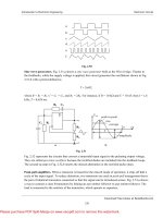
100'C - -
373.15 K - -
212('F) - -
671.67(R) - - Steam poinl
o'C---
273.15 K - -
32('F) - - -
491.67(R) - - Ice poinl
-273.15'C -
0 K---
-459.67(OF) -
O( R ) I - - - - - Absolute zero
Fllure 1.1 Relations among temperature scales.
t Except for the triple points and one equilibrium point (17.042 K), temperatures are for equilibrium states at l(atm).
The Celsius degree and the kelvin represent the same temperature interva~
as do the Fahrenheit degree and the rankine. However, I 'C (or I K) is equivalent
to 1.8('F) [or 1.8(R)]. The relationships among the four temperature scales are
shown in Fig. 1.1. In thermodynamics, when temperature is referred to without
qualification, absolute temperature is implied.
Example 1.2 Table 1.3 lists the specific volumes of water, mercury, hydrogen at I(atm),
and hydrogen at l00(atm) for a number oftemperatures on the International Practical
Temperature Scale. Assume that each substance is the fluid in a thermometer calibrated at the ice and steam points as suggested at the beginning of this sectidn. To
determine how good these thermometers are, calculate what each reads at the true
temperatures for which data are given.
The standard instrument used from -259.34 to 630.74'C is the platinumresistance thermometer, and from 630.74 to 1064.43'C the platinum-IO percent
rhodium/ platinum thermocouple is used. Above 1064.43'C the temperature is
defined by Planck's radiation law.
In addition to the Kelvin and Celsius scales two others are in use by
engineers in the United States: the Rankine scale and the Fahrenheit scale. The
Rankine scale is directly related to the Kelvin scale by
SOLUTION In calibrating a thermometer as specified, one assumes that each degree
is represented by a fixed scale length. This is equivalent to the assumption that each
degree of temperature change is accompanied by a fixed change in volume or specific
T(R) = 1.8T K
and is an absolute scale.
The Fahrenheit scale is related to the Rankine scale by an equation analogous
to the relation between the Celsius and Kelvin scales.
Table 1.3 Specifie volumes in em' g-'
t('F) = T(R) - 459.67
I/'e
Thus the lower limit of temperature on the Fahrenheit scale is -459.67('F). The
relation between the Fahrenheit and Celsius scales is given by
-100
0
50
100
200
t('F) = 1.8t'C + 32
This gives the ice point as 32('F) and the normal boiling point of water as 212('F).
Water
Mercury
H,I(alm)
H,IOO(atm)
0.073554
0.074223
0.074894
0.076250
7,053
11,125
13,161
15,197
19,266
76.03
118.36
139.18
159.71
200.72
....
1.00013
1.01207
1.04343
1.1590
8
INTRODUCTION TO CHEMICAL ENGINEERING THERMODYNAMICS
or per mole, and is therefore independent of the total amount of material
considered. Density, p is the reciprocal of specific or molar volume.
Table 1.4 Temperature readings for thermometers
f/OC
Water
Mercury
H2 t(atrn)
H 2 1OO(atm)
-100
0
50
100
200
0
27.6
100
367
0
49.9
100
201.2
-100.0
0
50.0
100
199.9
-102.3
0
50.4
100
199.2
volume of the thermometric fluid used. For water, the change in specific volume when
t increases from 0 to 100°C is
1.04343 - 1.00013
= 0.0433 em'
If it is assumed that this volume change divides equally among the 100°C. then the
volume change per degree is 0.000433 cm 3 °C- 1• When this assumption is not valid.
the thermometer gives readings in disagreement with the International Practical
Temperature Scale.
The change in specific volume of water between 0 and 50°C is
1.01207 - 1.00013
=
INTRODUCTION'
1.6 PRESSURE
The pressure P of a fluid on a surface is defined as the normal force exerted by
the fluid per unit area of the surface. If force is measured in N and area in m'
the unit is the newton per square meter or N m-', called the pascal, symbol Pa:
the basic SI unit of pressure. In the English engineering system the most common
unit is the pound force per square inch (psi).
The primary standard for the measurement of pressure derives from its
definition. A known force is balanced by a fluid pressure acting on a known area;
whence P = F / A. The apparatus providing this direct pressure measurement is
the dead-weight gauge. A simple design is shown in Fig. 1.2. The piston is carefully
fitted to the cylinder so that the clearance is small. Weights are placed on the
pan until the pressure of the oil, which tends to make the piston rise, is just
balanced by the force of gravity on the piston and all that it supports. With the
force of gravity given by Newton's law, the pressure of the oil is
p=F=mg
A
A
0.01194 em'
If each degree on the water thermometer represents 0.000433 cm3 , the number of
these degrees represented by a volume change of 0.01194 em' is 0.0\194/0.000433,
or 27.6(degrees). Thus the water thermometer reads 27.6(degrees) when the actual
r - - - - - - Weight
temperature is 50°C.
At 200~C. the specific volume of water is 1.1590 cm3 , and the change between 0
and 2oo·C'is 1.1590 - 1.00013 = 0.1589 em'. Thus the water thermometer reads
0.1589/0.000433, or 367(degrees), when the true temperature is 2OO·C. Table 1.4 gives
DllI'----- Pan
- - - - - - Piston
all the results obtained by similar calculations.
Each thermometer reads the true Celsius temperature at 0 and 100 because each
was calibrated at these points. At other points, however, the readings may differ from
the true values of the temperature. Water is seen to be a singularly poor thermometric
fluid. Mercury, on the other hand, is good, which accounts for its widespread use
in thermometers. Hydrogen at l(atm) makes a very good thermometric fluid, but is
not practical for general use. Hydrogen at lOO(atm) is no more practical and is less
satisfactory.
1.S DEFINED QUANTITIES; VOLUME
We have seen that in the international system of units force is defined through
Newton's law. Convenience dictates the introduction of a number of other defined
quantities. Some, like volume, are so common as to require almost no discussion.
Others, requiring detailed explanation, are treated in the following sections.
Volume V is a quantity representing the product of three lengths. The volume
of a substance, like its mass, depends on the amount of material considered.
Specific or molar volume, on the other hand, is defined as volume per unit mass
";~~ ........~ To pressure
!
Fipre 1.1 Dead-weight gauge.
source
10 INTRODUCTION TO CHEMICAL ENGINEERING THERMODYNAMICS
INTRODUCTION
where m is the mass of the piston, pan, and weights, 9 is the local acceleration
of gravity, and A is the cross-sectional area of the piston. Gauges in common
use, such as Bourdon gauges, are calibrated by comparison with dead-weight
gauges.
Since a vertical column of a given fluid under the influence of gravity exerts
a pressure at its base in direct proportion to its height, pressure is also expressed
as the equivalent height of a fluid column. This is the basis for the use of
manometers for pressure measurement. Conversion of height to force per unit
area follows from Newton's law applied to the force of gravity acting on the
mass of fluid in the column. The mass m is given by
1l
or
P
= 867.4kPa
Example 1.4 At 27°C a manometer filled with mercury reads 60.5 em. The local
acceleration of gravity is 9.784 m S-2. To what pressure does this height of mercury
correspond?
SOLUTION From the equation in the preceding text,
= hpg
P
At 27·C the density of mercury is 13.53 g em-'. Then
m =Ahp
P
where A is the cross-sectional area of the column, h is its height, and p is the
fluid density. Therefore
F mg Ahpg
P=-=-=--=hpg
A
A
A
=
Example 1.3 A dead-weight gauge with a l-cm-diameter piston is used to measure
pressures very accurately. In a particular instance a mass of 6.14 kg (including piston
anQ pan) brings it into balance. If the local acceleqltion of gravity is 9.82 m S-2, what
is the gauge pressure being measured? If the barometric pressure is 748(torr), what
is the absolute pressure?
or
P
= (6.14)(9.82) = 60.295 N
F
60.295
= 80.09 kPa = 0.8009 bar
1.7 WORK
Work W is done whenever a force acts through a distance. The quantity of work
done is defined by the equation
dW= Fdl
(1.1)
where F is the component of the force acting in the direction of the displacement
dt This equation must be integrated if the work for a finite process is required.
In engineering thermodynamics an important type of work is that which
accompanies a change in volume of a ftuid. Consider the compression or
expansion of a ftuid in a cylinder caused by the movement of a piston. The force
exerted by the piston on the ftuid is equal to the product of the piston area and
the pressure of the ftuid. The displacement of the piston is equal to the volume
change of the ftuid divided by the area of the piston. Equation (1.1) therefore
becomes
V
dW=PAdA
SOLUTION The force exerted by gravity on the piston, pan, and weights is
Gauge pressure = A = (1/4)( ,,)(1)2 = 76.77 N em
8,009 g m S-2 cm-2
or
The pressure to which a fluid height corresponds depends on the density of the
ftuid, which depends on its identity and temperature, and on the local ;lcceleration
of gravity. Thus the torr is the pressure equivalent of I millimeter ..J,finercury at
O·C in a standard gravitational field and is equal to 133.322 Pa.
Another unit of pressure is the standard atmosphere (atm), the approximate
average pressure exerted by the earth's atmosphere at sea level, defined as
101,325 Pa, 101.325 kPa, or 0.101325 MPa. The bar, an SI unit equal to 10' Pa,
is roughly the size of the atmosphere.
Most pressure gauges give readings which are the difference between the
pressure of interest and the pressure of the surrounding atmosphere. These
readings are known as gauge pressures, and can be converted to absolute pressures
by addition of the barometric pressure. Absolute pressures must be used in
thermodynamic calculations.
F = mg
= 60.5 em x 13.53 g em-' x 9.784 m S-2
or, since A is constant,
....
-2
dW= PdV
(1.2)
Integrating,
The absolute pressure is therefore
P
= 76.77 + (748)(0.013332) = 86.74 N em-2
v,
W=
I
v,
PdV
(1.3)
INTRODUCTION 13
12 INTRODUCTION TO CHEMICAL ENGINEERING THERMODYNAMICS
with Newton's second law becomes
dW = madl
By definition the acceleration is a = du/ dt, where u is the velocity of the body.
Thus
du
dW= m-dl
dt
which may be written
dl
dW= m-du
dt
p
Since the definition of velocity is u = dl/ dt, the expression for work becomes
v
Figure 1.3 PV diagram.
dW= mudu
This equation may now be integrated for a finite change in velocity from u, to u,:
Equation (1.3) is an expression for the work done as a result of a finite
compression or expllnsion process. t This kind of work can be represented as an
area on a pressure-vs.-volume (PV) diagram, such as is shown in Fig. 1.3. In this
case a gas having an initial volume V, at pressure P, is compressed to volume
V, at pressure P, along the path shown from I to 2. This path relates the pressure
at any point during the process to the volume. The work required for the process
is given by Eq. (1.3) and is represented on Fig. 1.3 by the area under the curve.
The SI unit of work is the newton-meter or joule, symbol J. In the English
engineering system the unit often used is the foot-pound force (ft Ib,).
W=m
f"'
Ul
or
W
= m2u~ _
(u' u')
udu=m 2_~
2 2
m;i = a( mn
(1.4)
Each of the quantities !mu' in Eq. (1.4) is a kinetic energy, a term introduced
by Lord Kelvint in 1856. Thus, by definition,
(1.5)
1.8 ENERGY
The general principle of conservation of energy was established about 1850. The
germ of this principle as it applies to mechanics was implicit in the work of
Galileo (1564-1642) and Isaac Newton (1642-1726). Indeed, it follows almost
automatically from Newton's second law of motion once work is defined as the
product of force and displacement. No such concept existed until 1826, when it
was introduced by the French mathematician J. V. Poncelet at the suggestion of
G. G. Coriolis, a French engineer. The word force (or the Latin vis) was used
not only in the sense described by NeWton in his laws of motion, but also was
applied to the quantities we now define as work and potential and kinetic energy.
This ambiguity precluded for some time the development of any general principle
of mechanics beyond Newton's laws of motion.
Several useful relationships follow from the definition of work as a quantitative and unambiguous physical entity. If a body of mass m is acted upon by the
force F during a differential interval of time dt, the displacement of the body
is dL The work done by the force F is given by Eq. (1.1), which when combined
t However. see Sec. 2.9 for limitations on its application.
Equation (1.4) shows that the work done on a body in accelerating it from an
initial velocity u, to a final velocity u, is equal to the change in kinetic energy
of the body. Conversely, if a moving body is decelerated by the action of a
resisting force, the work done by the body is equal to its change in kinetic energy.
In the SI system of units with mass in kg and velocity in m s-', kinetic energy
EK has the units of kg m' s-'. Since the newton is the composite unit kg m s-',
EK is measured in newton-meters or joules. In accord with Eq. (1.4), this is the
unit of work.
In the English engineering system, kinetic energy is expressed as !mu'/ goo
where g, has the value 32.1740 and the units (Ibm )(ft)(lb f )-'(s)-'. Thus the unit
of kinetic energy in this system is
E
- mu' _
(Ib m )(ft),(s)-'
2g, - (lb m )(ft)(Ib,) '(s)
K -
_ fi
( t Ib,)
2 -
Dimensional cd'nsistency here requires the inclusion of gc.
t Lord Kelvin, or William Thomson (1824-1907), was an English physicist who, along with the
German physicist Rudolf Clausius (1822-1888). laid the foundations for the modem science of
thermodynamics.
INTROOUCTION 15
14 INTRODUCTION TO CHEMICAL ENGINEERING THERMODYNAMICS
If a body of mass m is raised from an initial elevation z, to a final elevation
z an upward force at least equal to the weight of the body must be exerted on
itand this force must move through the distance z, - Z,. Since the weight of the
b~dy is the force of gravity on it, the minimum force required is given by Newton's
law as
F=ma=mg
where 9 is the local acceleration of gravity. The minimum work required to raise
the body is the product of this force and the change in elevation:
or
W
= mz,g -
mz,g
= Il(mzg)
(1.6)
We see from Eq. (1.6) that the work done on the body in raising it is equal to
the change in the quantity mzg. Conversely, if the body is lowered against a
resisting force equal to its weight, the work done by the body is equal to the
change in the quantity mzg. Equation (1.6) is similar in form to Eq. (1.4), and
both show that the work done is equal to the change in a quantity which describes
the condition of the body in relation to its surroundings. In each case the work
performed can be recovered by carrying out the reverse process and returning
the body to its initial condition. This observation leads naturally to the thought
that, if the work done on a body in accelerating it or in elevating it can be
subsequently recovered, then the body by virtue of its velocity or elevation must
contain the ability or capacity to do this work. This concept proved so useful in
rigid-body mechanics that the capacity of a body for doing work was given the
name energy, a word derived from the Greek and meaning "in work." Hence the
work of accelerating a body is said to produce a change in its kinetic energy, or
W
mu')
= IlEK = Il ( -2-
and the work done on a body in elevating it is said to produce a change in its
potential energy, or
W
= IlE p = Il(mzg)
Thus potential energy is defined as
Ep = mzg
(1.7)
This term was first proposed in 1853 by the Scottish engineer Willia,m Rankine
(1820-1872), In the SI system of units with mass in kg, elevation in m, and the
acceleration of gravity in m s-', potential energy has the units of kg m' s-'. This
is the newton-meter or joule, the unit of work, in agreement with Eq. (1.6).
In the English engineering system, potential energy is expressed as mzg / go'
Thus the unit of potential energy in this system is
E _ mzg _
p -
(Ibm)(ft)(ft)(s)-'
g, - (lbm)(ft)(lb,) '(s) ,
(ft Ib,)
Again, g, must be included for dimensional consistency.
In any examination of physical processes, an attempt is made to find or to
define quantities which remain constant regardless of the changes which occur,
One such quantity, early recognized in the development of mechanics, is mass.
The great utility of the law of conservation of mass as a general principle in
science suggests that further principles of conservation should be of comparable
value. Thus the development of the concept of energy logically led to the principle
of its conservation in mechanical processes. If a body is given energy when it is
elevated, then the body should conserve or retain this energy until it performs
the work of which it is capable. An elevated body, allowed to fall freely, should
gain in kinetic energy what it loses in potential energy so that its capacity for
doing work remains unchanged. For a freely falling body, we should be able to
write:
or
mu~ mui
2-2+ mz,g -
mz,g
=0
The validity of this equation has been confirmed by countless experiments. Success
in application to freely falling bodies led to the generalization of the principle
of energy conservation to apply to all purely mechanical processes, Ample experimental evidence to justify this generalization was readily obtained.
Other forms of mechanical energy besides kinetic and gravitational potential
energy are possible. The most obvious is potential energy of configuration. When
a spring is compressed, work is done by an external force. Since the spring can
later perform this work against a resisting force, the spring possesses capacity
for doing work. This is potential energy of configuration. Energy of the same
form exists in a stretched rubber band or in a bar of metal deformed in the elastic
region.
To increase the generality of the principle of conservation of energy in
mechanics, we look upon work itself as a form of energy. This is clearly permissible, because both kinetic- and potential-energy changes are equal to the work
done in producing them [Eqs. ( 1.4) and (1.6)]. However, work is energy in transit
and is never re!\l!.rded as residing in a body. When work is done and does not
appear simultaneously as work elsewhere, it is converted into another form of
energy.
The body or assemblage on which attention is focused is called the system.
All else is called the surroundings. When work is done, it is done by the surroundings on the system, or vice versa, and energy is transferred from the surroundings
16 INTRODUCTION TO CHEMICAL ENGINEERING THERMODYNAMICS
to the system, or the reverse. It is only during this transfer that the form of energy
known as work exists. In contrast, kinetic and potential energy reside with the
system. Their values, however, are measured with reference to the surroundings,
i.e., kinetic energy depends on velocity with respect to the surroundings, and
potential energy depends on elevation with respect to a datum level. Changes in
kinetic and potential energy do not depend on these reference conditions, provided they are fixed.
Example 1.5 An elevator with a mass of 2,500 kg rests at a level of 10m above the
base of an elevator shaft. It is raised to 100m above the base of the shaft, where the
cable holding it breaks. The elevator falls freely to the base of the shaft and strikes
a strong spring. The spring is designed to bring the elevator to rest and, by means of
a catch arrangement, to hold the elevator at the position of maximum spring compression. Assuming the entire process to be frictionless, and taking 9 = 9.8 m S-2,
calculate:
(a) The potential energy of the elevator in its initial position relative to the base
of the shaft.
(b) The work done in raising the elevator.
(c) The potential energy of the elevator in its highest position relative to the
base of the shaft.
(d) The velocity and kinetic energy of the elevator just before it strikes the spring.
(e) The potential energy of the compressed spring.
(f) The energy of the system consisting of the elevator and spring (I) at the
start of the process, (2) when the elevator reaches its maximum height, (3) just before
the elevator strikes the spring, and (4) after the elevator has come to rest.
SOLUTION Let SUbscript I designate the initial conditions; subscript 2, conditions
when the elevator is at its highest position; and SUbscript 3, conditions just before
the elevator strikes the spring.
(a) By Eq. (1.7),
E p , = mz,g = (2,500)(10)(9.8) = 245,000 1
(b) W =
J" Fdl = J" mgdl = mg(z, - z,)
z,
z)
whence
W
= (2,500)(9.8)(100 - 10) = 2,205,000 1
(e) E p , = mz,g = (2,500)(100)(9.8) = 2,450,0001
Note that W = Ep2 - Epl •
(d) From the principle of conservation of mechanical energy, one may write
that the sum of the kinetic- and potential-energy changes during the process from
conditions 2 to 3 is zero; that is,
or
INTRODUCTION
17
However, Exz and EI\ are zero. Therefore
EK )
=
Epl
=
2,450,000 J
Since E K , = !m"~,
,
"3 =
2EK ,
(2)(2,450,000)
m
2,500
whence
"3 =
(e)
f1Ep •Ptl".
44.27 m S-I
+ f1EK.,,!ev.u.r = 0
Since the initial potential energy of the spring and the final kinetic energy of the
elevator are zero, the final potential energy of the spring must equal the kinetic energy
of the elevator just before it strikes the spring. Thus the final potential energy of the
spring is 2,450,000 J.
(f) If the elevator and the spring together are taken as the system, the initial
energy of the system is the potential energy of the elevator, or 245,000 J. The total
energy of the system can change only if work is transferred between it and the
surroundings. As the elevator is raised, work is done on the system by the surroundings
in Ule, amount of 2,205,000 J. Thus the energy of the system when the elevator reaches
its maximum height is 245,000 + 2,205,000 = 2,450,000 1. Subsequent changes occur
entirely within the system, with no work transfer between the system and surroundings.
Hence the total energy of the system remains constant at 2,450,000 J. It merely changes
from potential energy of position (elevation) of the elevator to kinetic energy of the
elevator to potential energy of configuration of the spring.
This example serves to illustrate the application of the law of conservation of
mechanical energy. However, the entire process is assumed to occur without friction;
the results obtained are exact only for such an idealized process.
During the period of development of the law of conservation of mechanical
energy, heat was not generally recognized as a form of energy, but was considered
an indestructible fluid called caloric. This concept was so firmly entrenched that
no connection was made between heat resulting from friction and the established
forms of energy, and the law of conservation of energy was limited in application
to frictionless mechanical processes. Such a limitation is no longer appropriate;
the concept that heat like work is energy in transit gained acceptance during the
years following 1850, largely on account of the classic experiments of J. P. Joule
(1818-1889), a brewer of Manchester, England. These experiments are considered
in detail in Chap. 2, but first we examine some of the characteristics of heat.
1.9 HEAT
...
We know from experience that a hot object brought in contact with a cold object
becomes cooler, whereas the cold object becomes warmer. A reasonable view is
that something is transferred from the hot object to the cold one, and we call
that something heat Q. Two theories of heat developed by the Greek philosophers
18 INTRODUCTION TO CHEMICAL ENGINEERING THERMODYNAMICS
have been in contention until modern tillies. The one most generally accepted
until the middle of the nineteenth century was that heat is a weightless and
indestructible substance called caloric. The other represented heat as connected
in some way with motion, either of the ultimate particles of a body or of some
medium permeating all matter. This latter view was held by Francis Bacon,
Newton, Robert Boyle, and others during the seventeenth century. Without the
concept of energy this view could not be exploited, and by the middle of the
eighteenth century the caloric theory of heat gained ascendancy. However, a few
men of science did retain the other view, notably Benjamin Thompsont (17531814) and Sir Humphrey Davy (1778-1829). Both submitted experimental
evidence contrary to the caloric theory of heat, but their work went unheeded.
Moreover, the steam engine, a working example of the conversion of heat into
work, had been perfected by James Watt (1736-1819) and was in common use
at the time.
One notable advance in the theory of heat was made by Joseph Black
(1728-1799), a Scottish chemist and a collaborator of James Watt. Prior to Black's
time no distinction was made between heat and temperature, just as no distinction
was made between force and work. Temperature was regarded as the measure
of the quantity of heat or caloric in a body, and a thermometer reading was
referred to as a "number of degrees of heat." In fact, the word temperature still
had its archaic meaning of mixture or blend. Thus a given temperature indicated
a given mixture or blend of caloric with matter. Black correctly recognized
temperature as a property which must be carefully distinguished from quantity
of heat. In addition, he showed experimentally that different substances of the
same mass vary in their capacity to absorb heat when they are warmed through
the same temperature range. Moreover, he was the discoverer of latent heat. In
spite of the difficulty of explaining these phenomena by the caloric theory, Black
supported this theory throughout his life. Here the matter rested until near the
middle of the nineteenth century.
Among the early champions of the energy concept of heat were Mohr, Mayer,
and Helmholtz in Germany; Colding, a Dane; and especially James P. Joule in
England. Joule presented the experimental evidence which conclusively demonstrated the energy theory, and thus made possible the generalization of the law
of conservation of energy to include heat. The concept of heat as a form of energy
is now universally accepted and is implicit in the modern science of thermodynamics.
One of the most important observations about heat is that it always flows
from a higher temperature to a lower one. This leads to the concept of temperature
as the driving force for the transfer of energy as heat. More precisely, the rate
of heat transfer from one body to another is proportional to the temperature
difference between the two bodies; when there is no temperature difference, there
is no net transfer of heat. In the thermodynamic sense, heat is never !egarded
t Better known as Count Rumford. Born in Woburn. Mass .• unsympathetic to the American cause
during the Revolution. he spent most of his extraordinary Jife in Europe.
INTRODUCTION 19
as being stored within a body. Like work, it exists only as energy in transit from
one body to another, or between a system and its surroundings. When energy in
the form of heat is added to a body, it is stored not as heat but as kinetic and
potential energy of the atoms and molecules making up the body. Not surprisingly,
the energy theory of heat did not prevail until the atomic theory of matter was
well established.
In spite of the transient nature of heat, it is often thought of in terms of its
effects on the body from which or to which it is transferred. As a matter of fact
until about 1930 definitions of the quantitative units of heat were based on th~
temperature changes of a unit mass of water. Thus the calorie was long defined
as that quantity of heat which must be transferred to one gram of water to raise
its temperature one degree Celsius. Likewise, the British thermal unit, or (Btu),
was defined as that quantity of heat which must be transferred to one pound
mass of water to raise its temperature one degree Fahrenheit. Although these
definitions provide a "feel" for the size of heat units, they depend on the accuracy
of experiments made with water and are thus subject to change with each
incre~singly accurate measurement. The calorie and (Btu) are now recognized
as umts of energy, and are defined in relation to the joule, the only SI unit of
energy. It is defined as 1 N m, and is therefore equal to the mechanical work
done when a force of one newton acts through a distance of one meter. All other
energy u~its ar~ defined as multiples of the joule. The foot-pound jorce, for
example, IS eqUivalent to 1.3558179J, and the calorie to 4.184OJ. The SI unit of
power is the watt, symbol W, defined as an energy rate of one joule per second.
Appendix A gives an extensive table of conversion factors for energy as well
as for other units.
.
PROBLEMS
1.1 Using data given in Table 1.3, confirm one of the results given in the last three columns of Table
1.4.
1.2 Pr~ssures up to 3.000 bar are measured with a dead-weight gauge. The piston diameter is 0.35 cm.
What IS the approximate mass in kg of the weights required?
1.3 ,:essures up to 3.000(atm) are measured With a'dead-weight gauge. The piston diameter is
0.14(m). What is the approximate mass in (Ibm) of the weights required?
0
1.4 A mercury manometer at 20
e and open at one end to the atmosphere reads 38.72 cm. The local
~cceleration of gravity is 9.790 m s-z. Atmospheric pressure is 99.24 kPa. What is the absolute pressure
10 kPa being measured '!
1.5 A mercury manometer at 75(OF) and open at one end to the atmosphere reads 16.810n). The
local acceleration of gravity is 32.143(ft)(s)-z. Atmospheric pressure is 29.480n Hg). What is the
absolute pressure in (psi~ being measured?
~~. An. instrument to measure the acceleration of gravity on Mars is constructed of a spring from
Ich IS suspended a mass of 0.24 kg. At a place on earth where the local acceleration of gravity is
2
9.80ms. ext end s 061
. radios
.
,th
e spnng
. em. When t h·
e mstrument package .IS landed on Mars. It
the tnformation that the spring is extended 0.20 em. What is the Martian acceleration of gravity?
1.7 A group of engineers has landed on the moon, and would like to detennine the mass of several
unusual rocks. They have a spring scale calibrated to read pounds mass at a location where the
". INTRODUCTION TO CHEMICAL ENGINEERING THERMODYNAMICS
apceleration of gravity is 32.20(ft)(S)-2. One of the moon rocks gives a reading of 25 on the scale.
What is its mass? What is its weight on the moon? Take 9 moon = 5.47(ft)(s)-2.
.,8 gas is confined by a piston. 5(in) in diameter, on which rests a weight. The mass of the piston
¥d weight together is 6O(Ibm ). The local acceleration of gravity is 32.13(ft)(s)-2, and atmospheric
f)ressure is 30.16(in Hg).
(a) What is the force in (Ib r) exerted on the gas by the atmosphere, the piston. and the weight,
~suming no friction between the piston and cylinder?
(b) What is the pressure of the gas in (psia)?
(c) If the gas in the cylinder is heated. it expands. pushing the piston and weight upward. If
tfle piston and weight are raised 15(in). what is the work done by the gas in (ft lb r)? What is the
cbange in potential energy of the piston and weight?
1.9 A gas is confined by a pi~ton, 10 em in diameter, on which rests a weight. The mass of the piston
and weight together is 30 kg. The local acceleration of gravity is 9.805 m S-2, and atmospheric pressure
is 101.22 kPa.
(a) What is the force in newtons exerted on the gas by the atmosphere, the piston, and the
weight, assuming no friction between the piston and cylinder?
(b) What is the pressure of the gas in kPa?
(c) If the gas in the cylinder is heated, it expands, pushing the piston and weight upward. If
the piston and weight are raised 40 cm, what is the work done by the gas in kJ? What is the change
in potential energy of the piston and weight?
CHAPTER
A
TWO
THE FIRST LAW AND
OTHER BASIC CONCEPTS
1.10 Verify that the SI unit of kinetic and potential energy is the joule.
1.11 An automobile having a mass of 1,500 kg is traveling at 25 m S-I. What is its kinetic energy in
kJ? How much work must be done to bring it to a stop?
1.12 Liquid water at O°C and atmospheric pressure has a density of 1.000 g em- 3 . At the same
conditions, ice has a density of 0.917 g em- 3 • How much work is done at these conditions by 1 kg of
ice as it melts to liquid water?
2.1 JOULE'S EXPERIMENTS
During the years 1840-1878, J. P. Joulet carried out careful experiments on
the nature of heat and work. These experiments are fundamental to an understanding of the first law of thermodynamics and of the underlying concept of
energy.
In their essential elements Joule's experiments were simple enough, but he
took elaborate precautions to ensure accuracy. In his most famous series of
experiments, he placed measured amounts of water in an insulated container and
agitated the water with a rotating stirrer. The amounts of work done on the water
by the stirrer were accurately measured, and the temperature changes of the water
were carefully noted. He found that a fixed amount of work was required per
unit mass of water for every degree of temperature rise caused by the stirring.
The original temperature of the water could then be restored by the transfer of
heat through siIRJlle contact with a cooler object. Thus Joule was able to show
conclusively that a quantitative relationship exists between work and heat and,
therefore, that heat is a form of energy.
t For a fascinating account of Joule's celebrated experiments, see T. W. Chalmers, Historic
Researches, chap. II, Scribner. New York, 1952.
11 INTRODUCTION TO CHEMICAL ENGINEERING THERMODYNAMICS
2.2 INTERNAL ENERGY
In experiments such as those conducted by Joule, energy is added to the water
as work, but is extracted from the water as heat. The question arises as to what
happens to this energy between the time it is added to the water as work and the
time it is extracted as heat. Logic suggests that this energy is contained in the
water in another form, a form which we define as internal energy U.
The internal energy of a substance does not include any energy that it may
possess as a result of its macroscopic position or movement. Rather it refers to
the energy of the molecules making up the substance, which are in ceaseless
motion and possess kinetic energy of translation ; except for monatomic molecules,
they also possess kinetic energy of rotation and of internal vibration. The addition
of heat to a substance increases this molecular activity, and thus causes an increase
in its internal energy. Work done on the substance can have the same effect, as
was shown by Joule.
In addition to kinetic energy, the molecules of any substance possess potential
energy because of interactions among their force fields. On a submolecular scale
there is energy associated with the electrons and nuclei of atoms, and bond energy
resulting from the forces holding atoms together as molecules. Although absolute
values of internal energy are unknown, this is not a disadvantage in thermodynamic analysis, because only changes in internal energy are required.
The designation of this form of energy as internal distinguishes it from kinetic
and potential energy which the substance may possess as a result of its macroscopic
position or motion, and which can be thought of as external forms of energy.
2.3 FORMULATION OF THE
FIRST LAW OF THERMODYNAMICS
The recognition of heat and internal energy as forms of energy suggests a
generalization of the law of conservation of mechanical energy (Se~. 1.8) to ~pp~y
to heat and internal energy as well as to work and external potenllal and kinetIC
energy. Indeed, the generalization can be extended to still other f0n.ns, .such as
surface energy, electrical energy, and magnetic energy. This generahzallon was
at first no more than a postulate, but without exception all observations of ordinary
processes support it. t Hence it has achieved the stature of a law of nature, and
is known as the first law of thermodynamics. One formal statement is as follows:
Although energy assumes many forms, the total quantity of energy is constant, and
when energy disappears in one form it appears simultaneously in other forms.
In application of the first law to a given process, the sphere of influence of
the process is divided into two parts, the system and its surroundings. The part
t For nuclear.reaction processes, the Einstein equation applies, E
2
me , where c is the velocity
of light. Here, mass is transfonned into energy, and the laws of conservation of mass and energy
combine to state that mass and energy together are conserved.
=
THE FIRST LAW AND OTHER BASIC CONCEPTS 23
in which the process occurs is taken as the system. Everything not included in
the system constitutes the surroundings. The system may be of any size depending
on the particular conditions, and its boundaries may be real or imaginary, rigid
or flexible. Frequently a system is made up of a single substance; in other cases
it may be very complicated. In any event, the equations of thermodynamics are
written with reference to some well-defined system. This allows one to focus
attention on the particular process of interest and on the equipment and material
directly involved in the process.
However, the first law applies to the system and surroundings, and not to
the system alone. In its most basic form, the first law may be written:
/l(energy of the system) + /l(energy of surroundings) = 0
(2.1)
Changes may occur in internal energy of the system, in potential and kinetic
energy of the system as a whole, or in potential and kinetic energy of finite parts
of the system. Likewise, the energy change of the surroundings may consist of
increases or decreases in energy of various forms.
In the thermodynamic sense, heat and work refer to energy in transit across
the boundary between the system and its surroundings. These forms of energy
can never be stored. To speak of heat or work as being contained in a body or
system is wrong; energy is stored in its potential, kinetic, and internal forms.
These forms reside with material objects and exist because of the position,
configuration, and motion of matter. The transformations of energy from one
form to another and the transfer of energy from place to place often occur through
the mechanisms of heat and work.
If the boundary of a system does not permit the transfer of mass between
the system and its surroundings, the system is said to be closed, and its mass is
necessarily constant. For such systems all energy passing across the boundary
between system and surroundings is transferred as heat and work. Thus the total
energy change of the surroundings equals the net energy transferred to or from
it as heat and work, and the second term of Eq. (2.1) may be replaced by
/l(energy of surroundings) = ±Q ± W
The choice of signs used with Q and W depends on which direction of transfer
is regarded as positive.
The first term of Eq. (2.1) may be expanded to showe energy changes in
various forms. If the mass of the system is constant and if only internal-, kinetic-,
and potential-energy changes are involved,
...
/l( energy of the system) = /l U
+ /lEK + /lEp
With these substitutions, Eq. (2.1) becomes
/lU
+ /lEx + /lEp = ±Q ±
W
(2.2)
The traditional choice of signs on the right-hand side of Eq. (2.2) makes the
numerical value of heat positive when it is transferred to the system from the
surroundings, and the numerical value of work positive for the opposite direction
24 INTRODUCTION TO CHEMICAL ENGINEERING THERMODYNAMICS
THE FIRST LAW AND OTHER BASIC CONCEPTS
of transfer. With this understanding, Eq. (2.2) becomest
!1 U
+ !1EK + !1Ep
=
Q- W
(2.3)
In words, Eq. (2.3) states that the total energy change of the system is equal to
the heat added to the system minus the work done by the system. This equation
applies to the changes which occur in a constant-mass system over a period of time.
Closed systems often undergo processes that cause no changes in external
potential or kinetic energy, but only changes in internal energy. For such processes,
Eq. (2.3) reduces to
(2.4)
Equation (2.4) applies to processes involving finite changes in the system.
For differential changes this equation is written:
I dU= dQ-dW I
(2.5)
Equation (2.5) is useful when U, Q, and Ware expressed as functions of process
variables, and like Eq. (2.4) applies to closed systems which undergo changes in
internal energy only. The system must of course be clearly defined, as illustrated
in the examples of this and later chapters.
The units used in Eqs. (2.3) through (2.5) must be the same for all terms. In
the SI system the energy unit is the joule. Other energy units still in use are the
calorie, the foot-pound force, and the (Btu).
2.4 THE THERMODYNAMIC STATE
AND STATE FUNCTIONS
In thermodynamics we distinguish between two types of quantities: those which
depend on path and those which do not. Actually, both types are in everyday
use. Consider for example an automobile trip from New York to San Francisco.
The straight-line distance between these two cities is fixed; it does not depend
on the path or route taken to get from one to the other. On the other hand, such
measurements as miles traveled and fuel consumed definitely depend on the path.
So it is in thermodynamics; both types of quantities are used.
There are many examples of quantities which do not depend on path; among
them are temperature, pressure, and specific volume. We know from experience
that fixing two of these quantities automatically fixes all other such properties
of a homogeneous pure substance and, therefore, determines the condition or
t Those who prefer consistency over tradition make both heat and work positive for transfer to
the system from the surroundings. Eq. (2.2), then becomes
tJ.U+tJ.EK +tJ.Ep = Q+ W
l5
state of the substance. For example, nitrogen gas at a temperature of 300 K and
a pressure of \0' kPa (I bar) has a definite specific volume or density, a definite
viscosity, a definite thermal conductivity; in short it has a definite set of properties.
If this gas is heated or cooled, compressed or expanded, and then returned to
its initial conditions, it is found to have exactly the same set of properties as
before. These properties do not depend on the past history of the substance nor
on the path it followed in reaching a given state. They depend only on present
conditions, however reached. Such quantities are known as state functions. When
two of them are fixed or held at definite values for a homogeneous pure substance,
the thermodynamic state of the substance is fixed.
For systems more complicated than a simple homogeneous pure substance,
the number of properties or state functions that must be arbitrarily specified in
order to define the state of the system may be different from two. The method
of determining this number is the subject of Sec. 2.8.
Internal energy and a number of other thermodynamic variables (defined
later) are state functions and are, therefore, properties of the system. Since state
functions can be expressed mathematically as functions of thermodynamic coordinates such as temperature and pressure, their values can always be identified
with points on a graph. The differential of a state function is spoken of as an
infinitesimal change in the property. The integration of such a differential results
in a finite difference between two values of the property. For example,
p,
I
dP = P, - P, = !1P
and
I
u'
u,
P,
dU= U,- U, =!1U
Work and heat, on the other hand, are not state functions. Since they depend
on path, they cannot be identified witli'points on a graph, but rather are represented by areas, as shown in Fig. 1.3. The differeniials of heat and work are not
referred to as changes, but are regarded as infinitesimal quantities of heat and
work. When integrated, these differentials give not a finite change but a finite
quantity. Thus
I
dQ= Q
and
I
dW= W
Experiment shows that processes which accomplish the same change in state
by different paths in a closed system require, in general, different amounts of
he~t and work, but that the difference Q - W is the same for all such processes.
This gives experimental justification to the statement that internal energy is a
state function. Equation (2.4) yields the same value of!1U regardless of the path
~o~l~wed, provided only that the.change in the system is always from the same
100tiai to the same final state.
Another difference between state functions and heat or work is that a state
function represents a property of a system and always has a value. Work and
heat. appear only when changes are caused in a system by a process, which
requires time. Although the time required for a process cannot be predicted by
26 INTRODUCTION TO CHEMICAL ENGINEERING THERMODYNAMICS
thermodynamics alone, nevertheless the passage of time is inevitable whenever
heat is transferred or work is accomplished.
The internal energy of a system, like its volume, depends on the quantity of
material involved; such properties are said to be extensive. In contrast, temperature
and pressure, the principal thermodynamic coordinates for homogeneous ftuids,
are independent of the quantity of material making up the system, and are known
as intensive properties.
The first-law equations may be written for systems containing any quantity
of material; the values of Q, W, and the energy terms then refer to the entire
system. More often, however, we write the equations of thermodynamics for a
representative unit amount of material, either a unit mass or a mole. We can then
deal with properties such as volume and internal energy on a unit basis, in which
case they become intensive properties, independent of the quantity of material
actually present. Thus, although the total volume and total internal energy of an
arbitrary quantity of material are extensive properties, specific and molar volume
(or density) and specific and molar internal energy are intensive. Writing Eqs.
(2.4) and (2.5) for a representative unit amount of the system puts all of the
terms on a unit basis, but this does not make Q and W into thermodynamic
properties or state functions. Multiplication of a quantity on a unit basis by the
total mass (or total moles) of the system gives the total quantity.
Internal energy (through the enthalpy, defined in Sec. 2.5) is useful for the
calculation of heat and work quantities for such equipment as heat exchangers,
evaporators, distillation columns, pumps, compressors, turbines, engines, etc.,
because it is a state function. The tabulation of all possible Q's and W's for all
possible processes is impossible. But the intensive state functions, such as specific
volume and specific internal energy, are properties of matter, and they can be
measured and their values tablflated as functions of temperature and pressure
for a particular substance for future use in the calculation of Q or W for any
process involving that substance. The measurement, correlation, and use of these
state functions is treated in detail in later chapters.
Example 2.1 Water flows over a waterfall 100 m in height. Consider 1 kg ofthe water,
and assume that no energy is exchanged between the I kg and its surroundings.
(a) What is the potential energy of the water at the top of the falls with respect
to the base of the falls?
(b) What is the kinetic energy of the water just before it strikes bottom?
(c) After the I kg of water enters the river below the falls, what change has
occurred in its state?
SOLUTION Taking the I kg of water as the system, and noting that it ~xchanges
no energy with its surroundings, we may set Q and W equal to zero and write
Eq. (2.3) as
IJ.U+IJ.EK+IJ.Ep~O
This equation applies to each part of the process.
(a) From Eq. (1.7),
Ep
= mzg = 1 kg x 100 m x 9.8066 m S-2
THE FIRST LAW AND OTHER BASIC CONCEPTS
rI
where 9 has been taken as the standard value. This gives
Ep ~ 980.66 N m
or
980.66 J
(b) During the free fall of the water no mechanism exists for the conversion of
potential or kinetic energy into internal energy. Thus AU must be zero, and
IJ.EK
+ IJ.Ep
~ EK1 - EK I
For practical purposes we may take EKI
+ En
'--2
- EpI ~ 0
= Ep1 = O. Then
EK , ~ Ep , ~ 980.66 J
(c) ~ the I kg. of' water strikes bottom and mixes with other falling water to
form a. nve~, there IS much turbulence, which has the effect of converting kinetic
energy mto mternal energy. During this process, flEp is essentially zero, and Eq. (2.3)
becomes
or
IJ.U~EK,-EK,
However, the river velocity is assumed small, and therefore EK3 is negligible. Thus
IJ.U ~ EK, ~ 980.66J
!he ~verall result of the process is the conversion of potential energy of the water
mto mternal ~nergy of the water. This change in internal energy is manifested by a
temperature nse of ~he wat:r. ~ince energy in the amount of 4.IS4J kg-I is required
for a ote~peratur~ nse of I C 10 water, the temperature increase is 980.66/4,184 =
0.234 C, If there IS no heat transfer with the surroundings.
Exa~ple 2.2 A gas is confined in a cylinder by a piston. The initial pressure of the
gas. IS 7 bar, and the volume is 0.10 m3• The piston is held in place by latches in the
cylinder wall. The whole apparatus is placed in Motal vacuum. What is the energy
change of the appa~at~s ~~ the retaining latches are removed so that the gas suddenly
expands to double Its mltIal volume? The piston is again held by latches at the end
of the process.
SOLUTIO~ Since the q.uestion concerns the entire apparatus, the system is taken as
the gas, piston, and cylinder. No work is done during the process, because no force
~xtemal to the system moves, and no heat is transferred through the vacuum surround109 ~e apparatus. Hence Q and Ware zero, and the total energy of the system
r~m~lOs . unchanged. Without further information we can say nothing about the
distnbunon of energy among the parts of the system. This may well be different tha~
the initial distribution.
Exa~pl~ 2.3 If the process described in Example 2.2 is repeated, not in a vacuum
but 10 air at standard atmospheric pressure of 101.3 kPa, what is the energy change
of the apparatus? Assume the rate of heat exchange between the apparatus and the
surrounding air slow compared with the rate at which the process occurs.
SOLUTION. The s~tem is chosen exactly as before, but in this case work is done by
the system lo pushlOg back the atmosphere. This work is given by the product of the
f~rce exerted by the atmospheric pressure on the piston and the displacement of the
PIStOn. If the area of the piston is A, the force is F = PatmA The displacement of
THE FIRST LAW AND OTHER BASIC CONCEPTS 29
Z8 INTRODUCTION TO CHEMICAL ENGINEERING THERMODYNAMICS
This is the internal energy change for the state change from a to b by any path. Thus
the piston is equal to the volume change of the gas divided by the area of the piston,
or 6..1 = 6.. V / A. The work done by the system on the surroundings, according to
Eq. (1.1), is then
W ~ F AI ~ p ..m AV
for path aeb,
.1 U ab
W ~ (101.3)(0.2 - 0.1) ~ 10.13 kPa m'
~
10.13 kNm
~
AV
ba
~ -A Vab ~
Waeb = Qaeb -
20
Qbda ~
Example 2.4 When a system is taken from state a to state b in Fig. 2.1 along path
acb, 100 J of heat Hows into the system and the system does 40 J of work. How much
Qbda -
Wbda ~
Qbda -
(-30)
-60 - 30 ~ -90 J
Heat is therefore liberated from the system.
Q - W ~ 0 - 10.13 ~ -10.13 kJ
The total energy of the system has decreased by an amount equal to the work done
on the surroundings.
-60 ~
thus
in Eq. (2.3), giving
~
-
For path bda,
10.13 kJ
Heat transfer between the system and surroundings is also possible in this case, but
the problem is worked for the instant after the process has occurred and before
appreciable heat transfer has had time to take place. Thus Q is assumed to be zero
A(energy of the system)
= Qaeb
60
Qa.b ~80J
or
W
=
whence
2.5 ENTHALPY
In addition to internal energy a number of other thermodynamic functions are
~n common use ~ecause of their practical importance. Enthalpy (en-thar-py) is
heat Hows into the system along path aeb if the work done by the system is 20 J? The
system returns from b to a along the path bda. If the work done on the system is
30 J, does the system absorb or liberate heat? How much?
Introduced In thIs sectIOn, and others are treated later. Enthalpy is explicitly
defined for any system by the mathematical expression
SOLUTION We presume that the system changes only in its internal energy and that
I H= U+Pvl
Eq. (2.4) is applicable. For path acb,
6..Uab =
Qacb -
Wacb
=
100 - 40
= 60 J
where U = internal energy
P = absolute pressure
V = volume
The u~its of all terms of this equation must be the same. The product PV has
the umts of energy, as does U; therefore H also has units of energy. In the SI
system the basic unit of pressure is the pascal or N m- 2 and, for volume, the m'.
Thus the PV p.'oduct has the unit N m or JOUle. In the English engineering system
~ common umt for the PV product is the (ft lb,), which arises when pressure is
~ (.I~,)(ft)-2 with volume in (ft)'. This result is usually converted to (Btu) through
d,,:,slOn by 778.16 for use in Eq. (2.6), because the common English engineering
Umt for U and H is the (Btu).
Since U, P, and V are all state functions, H as defined by Eq. (2.6) must
also be a state function. In differential form Eq. (2.6) may be written
b
p
dH = dU + d(PV)
(2.7)
This eq~ation applies whenever a differential change occurs in the system.
Integrahon of Eq. (2.7) gives
a ~_-''''''''
v
(2.6)
Figure 1.1 Diagram for Example 2.4.
;n
AH
~
AU + A(PV)
(2.8)
equation applicable whenever a finite change occurs in the system. Equations
2.6) through (2.8) may be written for any amount of material, though they are
30
INTRODUCTION
TO
CHEMICAL
ENQINbbKINU .HI::.KMUUINR.MI .......,
THE FIRST LAW AND OTHER BASIC CONCEPTS
often applied to a unit mass or to a mole. Like volume and internal energy,
enthalpy is an extensive property; specific or molar enthalpy is of course intensive.
Enthalpy is useful as a thermodynamic property because the U + PV group
appears frequently, particularly in problems involving flow processes, as illustrated in Sec. 2.6. The calculation of a numerical value for llH is carried out in
the following example.
31
u,
Section I
Heat
exchanger
Q--I-
Example 1.S Calculate !1 U and AH for 1 kg of water when it is vaporized at the
dz
constant temperature of 100°C and the constant pressure of 101.33 kPa. The specific
3
volumes of liquid and vapor water at these conditions are 0.00104 and 1.673 m kg-I.
For this change, heat in the amount of 2,256.9 kJ is added to the water.
u,
The kilogram of water is taken as the system, because it alone is of
interest. We imagine the fluid contained in a cylinder by a frictionless piston which
exerts a constant pressure of 101.33 kPa. As heat is added, the water expands from
its initial to its final volume, doing work on the piston. By Eq. (1.3),
SOLUTION
W =
Section 2
P a v = 101.33 kPa x (1.673 - 0.001) m'
Z2
w,
whence
W =
Since Q
169.4 kPam' = 169.4kN m- 2 m' = 169.4 kJ
= 2,256.9 kJ, Eq. (2.4) gives
au = Q - W = 2,256.9 - 169.4 = 2,087.5 kJ
Figure 2.2 Steady-state flow process.
arbitra~y datum level of z" an av~rage
With P constant, Eq. (2.8) becomes
aH=aU+pav
But P a v = W. Therefore
aH = au + W =
Datum level
Q = 2,256.9 kJ
2.6 THE STEADY-STATE FLOW PROCESS
The applIcation of Eqs. (2.4) and (2.5) is restricted to nonflow (constant mass)
processes in which only internal-energy changes occur. Far more important
industrially are processes which involve the steady-state flow of a fluid through
equipment. For such processes the more general first-law expression [Eq. (2.3)]
must be used. However, it may be put in more convenient form. The term steady
state implies that conditions at all points in the apparatus are constant with time.
For this to be the case, all rates must be constant, and there must be no
accumulation of material or energy within the apparatus over the period of time
considered. Moreover, the total mass flow rate must be the same at all points
along the path of flow of the fluid.
Consider the general case of a steady-state-f1ow process as represented in
Fig. 2.2. A fluid, either liquid or gas, flows through the apparatus from section
I to section 2. At section I, the entrance to the apparatus, conditions in the fluid
are denoted by subscript I. At this point the fluid has an elevation above an
velocity u" a specifiicvolume V" a pressure
PI, an tntemal energy U I , etc. Similarly, the conditions 'in the fluid at section 2
the exit of the apparatus, are denoted by subscript 2.
'
The system is taken as a unit mass of the fluid, a";!d we consider the overall
changes ~hich occur ~n this unit mass of fluid as it flows through the apparatus
from sectIOn I to sectIOn 2. The energy of the unit mass may change in all three
~f the forms taken into account by Eq. (2.3), that is, potential, kinetic, and
tntemal. The kinetic-energy change of a unit mass of fluid between sections I
and 2 follows from Eq. (1.5):
aE
K
= !u~
- !ui = !au
2
In this equatio~ u represents the average velocity of the flowing fluid, defined
as the volumetnc flow rate divided by the cross-sectional area. t As a result of
Eq ..(1.7) we have for the potential-energy change of a unit mass of fluid between
sectIOns I and 2
llEp
= z,g - zig = g llz
Equation (2.3) now becomes
llu'
llU+T+gllz=Q-W
.
IS
(2.9)
t ~e development of the expression 1U 2 for kinetic energy in terms of the average fluid velocity
Consldered in detail in Chap. 7.
32 INTRODUCTION TO CHEMICAL ENGINEERING THERMODYNAMICS
where Q and W represent all the heat added and work extracted per unit mass
of fluid flowing through the apparatus.
It might appear that W is just the shaft work W, indicated in Fig. 2.2, but
this is not the case. The term shaft work means work done by or on the fluid
flowing through a piece of equipment and transmitted by a shaft which protrudes
from the equipment and which rotates or reciprocates. Therefore, the term
represents the work which is interchanged between the system and its surroundings
through this shaft. In addition to W, there is work exchanged between the unit
mass of fluid taken as the system and the fluid on either side of it. The element
of fluid regarded as the system may be imagined as enclosed by flexible diaphragms
and to flow through the apparatus as a fluid cylinder whose dimensions respond
to changes in cross-sectional area, temperature, and pressure. As illustrated in
Fig. 2.2, a free-body drawing of this cylinder at any point along its path shows
pressure forces at its ends exerted by the adjacent fluid. These forces move with
the system and do work. The force on the upstream side of the cylinder does
work on the system. The force on the downstream side is in the opposite direction
and results in work done by the system. From section I to section 2 these two
pressure forces follow exactly the same path and vary in exactly the same manner.
Hence, the net work which they produce between these two sections is zero.
However, the terms representing work done by these pressure forces as the fluid
enters and leaves the apparatus do not, in general, cancel. In Fig. 2.2 the unit
mass of fluid is shown just before it enters the apparatus. This cylinder of fluid
has a volume VI equal to its specific volume at the conditions existing at section
I. If its cross-sectiional area is AI. its length is VI/AI' The force exerted on its
upstream face is PIAl, and the work done by this force in pushing the cylinder
into the apparatus is
This represents work done on the system by the surroundings. At section 2 work
is done by the system on the surroundings as the fluid cylinder emerges from the
apparatus. This work is given by
W,
=
V,
P,A,-
A,
=
P, V,
Since W in Eq. (2.9) represents all the work done by the unit mass of fluid, it
is equal to the algebraic sum of the shaft work and the entrance and exit work
quantities; that is,
In combination with this result, Eq. (2.9) becomes
Il.u'
Il.U +2+ g Il.z = Q -
w, -
P,V, + PI VI
THE FIRST LAW AND OTHER BASIC CONCEPTS
33
or
But by Eq. (2.8),
Il.U + Il.(PV) = Il.H
Therefore,
(2.lOa)
This equation is the mathematical expression of the first law for a steady-state-flow
process. All the terms are expressions for energy per unit mass of fluid; in the
SI system of units, energy is expressed in joules or in some multiple of the JOUle.
For the English engineering system of units, this equation must be reexpressed
to include the dimensional constant g, in the kinetic- and potential-energy terms:
Il.u' g
Il.H +-+-Il.z = Q - W
2gc
gc
(2. lOb)
S
Here, the usual unit for Il.H and Q is the (Btu), whereas kinetic energy, potential
energy, and work are usually expressed as (J!lb,). Therefore the factor
778.16(ft Ib,)(Btu)-1 must be used with the appropriate terms to put them all in
consistent units of either (ft Ib,) or (Btu).
For many of the applications considered in thermodynamics, the kinetic- and
potential-energy terms are very small compared with the others and may be
neglected. In such a case Eq. (2.10) reduces to
Il.H = Q - W,
(2.1 1)
This expression of the first law for a steady-How process is analogous to Eq. (2.4)
~or a nonflow process. Here, however, the enthalpy rather than the internal energy
IS the thermodynamic property of importance.
. Equations (2.10) and (2.11) are universally used for the solution of problems
Involving the steady-state How of Huids through equipment. For most such
applications values of the enthalpy must be available. Since H is a state function
and a property of matter, its values depend only on point conditions; once
determined, they may be tabulated for subsequent use whenever the same sets
of conditions are encountered again. Thus Eq. (2.10) may be applied to laboratory
processes designed specifically for the determination of enthalpy data.
. . One such process employs a flow calorimeter. A simple example of this device
~s Illustrated schematically in Fig. 2.3. Its essential feature is an electric heater
Immersed in a Howing Huid. The apparatus is designed so that the kinetic- and
potential-energy changes of the Huid from section I to section 2 (Fig. 2.3) are
34
INTRODUCTION TO CHEMICAL ENGINEERING THERMODYNAMICS
T,
Section 1
,
,
,
Constant
temperatu Te
bath
-r
-
Heater
I/' 'V r----l
energy, are unknown. An arbitrary value may therefore be assigned to H, as the
basis for all other enthalpy values. If we set H, = 0 for liquid water at O·C, then
the values of H, are given by
P,
,'0
,
,
V~ve
~
Discharge
,
Section 2
f-c
----
Applied
emf
Supply ----..
r
H,
=
H, + Q
=
0+ Q
=
Q
:
I
--:'"'!!
THE FIRST LAW AND OTHER BASIC CONCEPI'S 35
Pump
?-Figure 2.3 Flow calorimeter.
negligible. This requires merely that the two sections be at the same elevation
and that the velocities be small. Furthermore, no shaft work is accomplished
between sections I and 2. Hence Eq. (2.10) reduces to
AH
= H,-H , = Q
Heat is added to the fluid from the electric resistance heater; the rate of energy
input is determined from the resistance of the heater and the current passing
through it. The entire apparatus is well insulated. In practice there are a number
of details which need attention, but in principle the operation of the flow
calorimeter is simple. Measurements of the rate of heat input and the rate of
flow of the fluid allow calculation of values of AH between sections I and 2.
As an example, consider the measurement of enthalpies of H,O, both as
liquid and as vapor. Liquid water is supplied to the apparatus by the pump. The
constant-temperature bath might be filled with a mixture of crushed ice and water
to maintain a temperature of o·c. The coil which carries the test fluid, in this
case, water, through the constant-temperature bath is made long enough so that
the fluid emerges essentially at the bath temperature of O·C. Thus the fluid at
section I is always liquid water at o·c. The temperature and pressure at section
2 are measured by suitable instruments. Values of the enthalpy of H,O for various
conditions at section 2 may be calculated by the equation
H,= H, +Q
where Q is the heat added by the resistance heater per unit mass of water flowing.
Clearly, H, depends not only on Q but also on H,. The conditions at section I
are always the same, i.e., liquid water at O·C, except that the pressure varies from
run to run. However, pressure has a negligible eflect on the properties ·of liquids
unless very high pressures are reached, and for practical purposes H, may be
considered a constant. Absolute values of enthalpY,like absolute values of internal
These results may be tabulated along with the corresponding conditions of T
and P existing at section 2 for a large number of runs. In addition, specific-volume
measurements may be made for these same conditions, and these may be tabulated. Corresponding values of the internal energy of water may be calculated
by Eq. (2.6), U = H - Pv, and these numbers too may be tabulated. In this way
tables of thermodynamic properties may be compiled over the entire useful range
of conditions. The most widely used such tabulation is for H,O and is known as
the steam tables. t
The enthalpy may be taken as zero for some other state than liquid at O·C.
The choice is arbitrary. The equations of thermodynamics, such as Eq. (2.10),
apply to changes of state, for which the enthalpy differences are independent of
where the origin of values is placed. However, once an arbitrary zero point is
selected for the enthalpy, an arbitrary choice cannot be made for the internal
energy, for values of internal energy are then calculable from the enthalpy by
Eq. (2.6).
Example 2.6 For the Bow calorimeter just discussed, the following data are taken
with water as the test Ouid:
Flow rate = 4.15 g S-I
P2=3bar
Rate of heat addition from resistance heater
=
12,740 W
It is observed that the water is completely vaporized in the process. Calculate the
enthalpy of steam at 300°C and 3 bar based on H = 0 for liquid water at ooe.
SOLUTION If.i1z and .i1u are negligible and if ~ and HI are zero. then Hz
2
H,
= I~:;~~ S~1
= Q. and
3,070J g-I
Example 2.7 Air at 1 bar and 25°C enters a compressor at low velocity, discharges at
3 bar. and enters a nozzle in which it expands to a final velocity of 600 m s -I at the
initial conditions of pressure and temperature. If the work of compression is 240 kJ
per kilogram of air, how much heat must be removed during compression?
SOLUTION Since the air returns to its initial conditions of T and Po. the overall
process produces no change in enthalpy of the air. Moreover, the potential-energy
change of the air is presumed negligible. Neglecting also the initial kinetic energy of
t Steam tables are given in App. C. Tables for varjpus other substances are found in the literature.
A discussion of compilations of thermodynamic properties appears in Chap. 6.