Process systems analysis and control 2nd ed (1991)
Bạn đang xem bản rút gọn của tài liệu. Xem và tải ngay bản đầy đủ của tài liệu tại đây (10.83 MB, 584 trang )
Pi
PROCESS SYSTEMS ANALYSIS AND CONTROL
McGraw-Hill Chemical Engineering Series
Editorial Advisory Board
James J. Carherry, Professor of Chemical Engineering, University of Notre Dame
James R. Fair, Professor of Chemical Engineering, University of Texas, Austin
William P. Schowalter, Dean, School of Engineering, University of Illinois
Matthew llrrell, Professor of Chemical Engineering, University of Minnesota
James Wei, Professop of Chemical Engineering, Massachusetts Institute of Technology
Max S. Peters, Emeritus, Professor of Chemical Engineering, University of Colorado
Building the Literature of a Profession
Fifteen prominent chemical engineers first met in New York more than 60 years
ago to plan a continuing literature for their rapidly growing profession. From
Industry came such pioneer practitioners as Leo H. Baekeland, Arthur D. Little,
Charles L. Reese, John V. N. Dot-r, M. C. Whitaker, and R. S. McBride. From
the universities came such eminent educators as William H. Walker, Alfred H.
White, D. D. Jackson, J. H. James, Warren K. Lewis, and Harry A. Curtis.
H. C. Parmelee, then editor of Chemical und Metullurgical Engineering, served
as chairman and was joined subsequently by S. D. Kirkpatrick as consulting editor.
After several meetings, this committee submitted its report to the McGrawHill Book Company in September 1925. In the report were detailed specifications
for a correlated series of more than a dozen texts and reference books which
have since become the McGraw-Hill Series in Chemical Engineering and which
became the cornerstone of the chemical engineering curriculum.
From this beginning there has evolved a series of texts surpassing by far the
scope and longevity envisioned by the founding Editorial Board. The McGrawHill Series in Chemical Engineering stands as a unique historical record of the
development of chemical engineering education and practice. In the series one
finds the milestones of the subject’s evolution: industrial chemistry, stoichiometry,
unit operations and processes, thermodynamics, kinetics, process control, and
transfer operations.
Chemical engineering is a dynamic profession, and its literature continues
to evolve. McGraw-Hill, with its editor, B.J. Clark and its consulting editors,
remains committed to a publishing policy that will serve, and indeed lead, the
needs of the chemical engineering profession during the years to come.
The Series
Bailey and Ollis: Biochemical Engineering Fundamentals
Bennett and Myers: Momentum, Heat, and Mass Transfer
Brodkey and Hershey: Transport Phenomena: A Unified App
Carberry: Chemical and Catalytic Reaction Engineering
Constantinides: Applied Numerical Methods with Personal C o
Coughanowr: Process Systems Analysis and Control
Douglas: Conceptual Design of Chemical Processes
Edgar and Himmelblau: Optimization of Chemical Processes
Gates, Katzer, and Schuit: Chemistry of Catalytic Processes
Holland: Fundamentals of Multicomponent Distillation
Holland and Liapis: Computer Methods for Solving Dynamic Separation Problems
Katz and Lee: Natural Gas Engineering: Production and Storage
King: Separation Processes
Lee: Fundamentals of Microelectronics Processing
Luyben: Process Modeling, Simulation, and Control for Chemical Engineers
McCabe, Smith, J. C., and Harriott: Unit Operations of Chemical Engineering
Mickley, Sherwood, and Reed: Applied Mathematics in Chemical Engineering
Nelson: Petroleum ReJinery Engineering
Perry and Chilton (Editors): Perry’s Chemical Engineers’ Handbook
Peters: Elementary Chemical Engineering
Peters and ‘Dmmerhaus: Plant Design and Economics for Chemical Engineers
Reid, Prausnitz, and Rolling: Properties of Gases and Liquids
Smith, J. M.: Chemical Engineering Kinetics
Smith, J. M., and Van Ness: Introduction to Chemical Engineering Thermodynamics
‘Deybal: Mass Transfer Operations
Valle-Riestra: Project Evaluation in the Chemical Process Industries
Wei, Russell, and Swartzlander: The Structure of the Chemical Processing Industries
Wentz: Hazardous Waste Management
PROCESS SYSTEMS ANALYSIS
Second Edition
Donald R. Coughanowr
Department of Chemical Engineering
Drexel University
McGraw-Hill, Inc.
New York St. Louis San Francisco Auckland Bogota Caracas
Hamburg Lisbon London Madrid Mexico Milan Montreal New Delhi
Paris San Juan S2o Paul0 Singapore Sydney Tokyo Toronto
PROCESS SYSTEMS ANALYSIS AND CONTROL
International
Edition
1991
Exclusive rights by McGraw-Hill Book Co.- Singapore for
manufacture and export. This book cannot be re-exported
from the country to which it is consigned by McGraw-Hill.
Copyright @ 1991, 1965 by McGraw-Hill, Inc.
All rights reserved. Except as permitted under the United States Copyright
Act of 1976, no part of this publication may be reproduced or distributed in
any form or by any means, or stored in a data base or retrieval system,
without the prior written permission of the publisher.
34167890BJEFC965432
This book was set in Times Roman by Publication Services.
The editors were B. J. Clark and John M. Morriss.
The production supervisor was Louise Karam.
The cover was designed by Rafael Hernandez.
Project supervision was done by Publication Services.
Library of Congress Cataloging in Publication Data
Coughanowr, Donald R.
Process systems analysis and control / by Donald Ft. Coughanowr. 2nd ed.
cm. - (McGraw-Hill chemical engineering series)
P.
Includes index.
ISBN o-07-013212-7
1. Chemical process control. I. Title. II. Series.
TP155.75C68
1991
660’.02815-dc20
90-41740
When ordering this title use ISBN 0-07-l 00807-l
ABOUTTHEAUTHOR
Donald R. Coughanowr is the Fletcher Professor of Chemical Engineering at
Drexel University. He received a Ph.D. in chemical engineering from the University of Illinois in 1956, an MS. degree in chemical engineering from the
University of Pennsylvania in 195 1, and a B . S. degree in chemical engineering
from the Rose-Hulman Institute of Technology in 1949. He joined the faculty
at Drexel University in 1967 as department head, a position he held until 1988.
Before going to Drexel, he was a faculty member of the School of Chemical
Engineering at Purdue University for eleven years.
At Drexel and Purdue he has taught a wide variety of courses, which include material and energy balances, thermodynamics, unit operations, transport
phenomena, petroleum refinery engineering, environmental engineering, chemical
engineering laboratory, applied mathematics, and process dynamics and control.
At Purdue, he developed a new course and laboratory in process control and collaborated with Dr. Lowell B. Koppel on the writing of the first edition of Process
Systems Analysis and Control.
His research interests include environmental engineering, diffusion with
chemical reaction, and process dynamics ,and control; Much. of his research in
control has emphasized the development and evaluation of new.control algorithms
for processes that cannot be controlled easily by ,cpnventional control; some of
the areas investigated are time%p~inkl control, adaptive pH control, direct digital
control, and batch control of fermentors. He has reported on his research in numerous publications and has received support for research projects from, the N.S .I!
and industry. He has spent sabbatical leaves teaching and writing at Case-Western
Reserve University, the Swiss, Federal Institute, the University of Canterbury, the
University of New South Wales, the University of Queensland, and Lehigh University.
Dr. Coughanowr’s industrial experience includes process design and pilot
plant at Standard Oil Co. (Indiana) and summer employment at Electronic Associates and Dow Chemical Company.
...
Vlll
ABOUT THE AUTHOR
He is a member of the American Institute of Chemical Engineers, the Instrument Society of America, and the American Society for Engineering Education.
He is also a delegate to the Council for Chemical Research. He has served the
AIChE by participating in accreditation visits to departments of chemical engineering for. ABET and by chairing sessions of the Department Heads Forum at
the annual meetings of AIChE.
To
Effie, Corinne, Christine, and David
CONTENTS
Preface
1 An Introductory Example
xv
1
Part I The Laplace Transform
2
3
4
The Laplace Transform
Inversion by Partial Fractions
Further Properties of Transforms
13
22
37
Part II Linear Open-Loop Systems
Response of First-Order Systems
Physical Examples of First-Order Systems
49
7 Response of First-Order Systems in Series
8 Higher-Order Systems: Second-Order
and Transportation Lag
80
5
6
64
90
Part III Linear Closed-Loop Systems
9
10
The Control System
Controllers and Final Control Elements
111
11
Block Diagram of a Chemical-Reactor Control System
135
123
xi
x i i CONTENTS
12
Closed-Loop Transfer Functions
1 3 Transient Response of Simple Control Systems
1 4 Stability
1 5 Root Locus
143
151
164
177
Part IV Frequency Response
16 Introduction to Frequency Response
1 7 Control System Design by Frequency Response
201
224
Part V Process Applications
18
19
20
21
Advanced Control Strategies
Controller Tuning and Process Identification
Control Valves
Theoretical Analysis of Complex Processes
249
282
303
318
.
Part VI
Sampled-Data Control Systems
22
23
24
25
Sampling and Z-Transforms
Open-Loop and Closed-Loop Response
Stability
Modified Z-Transforms
26
Sampled-Data Control of a First-Order Process
with Transport Lag
Design of Sampled-Data Controllers
27
349
360
376
384
-393
405
Part VII State-Space Methods
28
29
30
State-Space Representation o f Physical Systems
Transfer Function Matrix
Multivariable Control
431
446
453
CONTENTS
...
xl11
Part VIII Nonlinear Control
31
32
33
Examples of Nonlinear Systems
Methods of Phase-Plane Analysis
The Describing Function Technique
Part IX
471
484
506
Computers in Process Control
34 Digital Computer Simulation of Control Systems
35 Microprocessor-Based Controllers and Distributed
Control
Bibliography
Index
517
543
559
561
PREFACE
Since the first edition of this book was published in 1965, many changes have
taken place in process control. Nearly all undergraduate students in chemical
engineering are now required to take a course‘in process dynamics and control.
The purpose of this book is to take the student from the basic mathematics to a
variety of design applications in a clear, concise manner.
The most significant change since the first edition is the use of the digital
computer in complex problem-solving and in process control instrumentation.
However, the fundamentals of process control, which remain the same, must be
acquired before one can appreciate the advanced topics of control.
In its present form, this book represents a major revision of the first edition.
The material for this book evolved from courses taught at Purdue University and
Drexel University. The first 17 chapters on fundamentals are quite close to the
first 20 chapters of the first .edition. The remaining 18 chapters contain many
new topics, which were considered very advanced when the first edition was
published.
A knowledge of calculus, unit operations, and complex numbers is presumed
on the part of the student. In certain later chapters, more advanced mathematical
preparation is useful. Some examples would include partial differential equations
in Chap. 21, linear algebra in Chaps. 28-30, and Fourier series in Chap. 33.
Analog computation and pneumatic controllers in the first edition have been
replaced by digital computation and microprocessor-based controllers in Chaps.
34 and 35. The student should be assigned material from these chapters at the
appropriate time in the development of the fundamentals. For example, obtaining
the transient response for a system containing a transport lag can be obtained easily
only with the use of computer simulation of transport lag. Some of the software
now available for solving control problems should be available to the student;
such software is described in Chap. 34. To understand the operation of modem
microprocessor-based controllers, the student should have hands-on experience
with these instruments in a laboratory.
XV
Xvi
PREFACE
Chapter 1 is intended to meet one of the problems consistently faced in presenting this material to chemical engineering students, that is, one of perspective.
The methods of analysis used in the control area are so different from the previous
experiences of students that the material comes to be regarded as a sequence of
special mathematical techniques, rather than an integrated design approach to a
class of real and practically significant industrial problems. Therefore, this chapter presents an overall, albeit superficial, look at a simple control-system design
problem. The body of the text covers the following topics:
1 . Laplace transforms, Chaps 2 to 4.
2. Transfer functions and responses of open-loop systems, Chaps. 5 to 8.
3. Basic techniques of closed-loop control, Chaps. 9 to 13.
4. Stability, Chap. 14.
5 . Root-locus methods, Chap. 15.
6. Frequency-response methods and design, Chaps. 16 and 17.
7. Advanced control strategies (cascade, feedforward, Smith predictor, internal
model control), Chap. 18.
8. Controller tuning and process identification, Chap. 19.
9. Control valves, Chap. 20.
10. Advancedprocess
dynamics, Chap. 21.
11. Sampled-data control, Chaps. 22 to 27.
12. State-space methods and multivariable control, Chaps. 28 to 30.
13. Nonlinear control, Chaps. 31 to 33.
14. Digital computer simulation, Chap. 34.
15. Microprocessor-based controllers, Chap. 35.
It has been my experience that the book covers sufficient material for a onesemester (15-week) undergraduate course and an elective undergraduate course or
part of a graduate course. In a lecture course meeting three hours per week during
a lo-week term, I have covered the following Chapters: 1 to 10, 12 to 14, 16,
17, 20, 34, and 35.
After the first 14 chapters, the instructor may select the remaining chapters
to fit a course of particular duration and scope. The chapters on the more advanced
topics are written in a logical order; however, some can be skipped without creating
a gap in understanding.
I gratefully acknowledge the support and encouragement of the Drexel University Department of Chemical Engineering for fostering the evolution of this
text in its curriculum and for providing clerical staff and supplies for several editions of class notes. I want to acknowledge Dr. Lowell B. Koppel’s important
contribution as co-author of the first edition of this book. I also want to thank
my colleague, Dr. Rajakannu Mutharasan, for his most helpful discussions and
suggestions and for his sharing of some of the new problems. For her assistance
PREFACE
Xvii
in typing, I want to thank Dorothy Porter. Helpful suggestions were also provided
by Drexel students, in particular Russell Anderson, Joseph Hahn, and Barbara
Hayden. I also want to thank my wife Effie for helping me check the page proofs
by reading to me the manuscript, the subject matter of which is far removed from
her specialty of Greek and Latin.
McGraw-Hill and I would like to thank Ali Cinar, Illinois Institute of Technology; Joshua S. Dranoff, Northwestern University; H. R. Heichelheim, Texas
Tech University; and James H. McMicking, Wayne State University, for their
many helpful comments and suggestions in reviewing this second edition.
Donald R. Coughanowr
1
CHAPTER
ANINTRODUCTORY
EXAMPLE
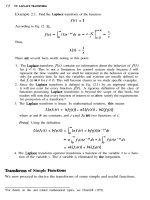
In this chapter we consider an illustrative example of a control system. The goal
is to introduce some of the basic principles and problems involved in process
control and to give the reader an early look at an overall problem typical of those
we shall face in later chapters.
The System
A liquid stream at temperature Ti is available at a constant flow rate of w in units
of mass per time. It is desired to heat this stream to a higher temperature TR. The
proposed heating system is shown in Fig. 1.1. The fluid flows into a well-agitated
tank equipped with a heating device. It is assumed that the agitation is sufficient
to ensure that all fluid in the tank will be at the same temperature, T. Heated fluid
is removed from the bottom of the tank at the flow rate w as the product of this
heating process. Under these conditions, the mass of fluid retained in the tank
remains constant in time, and the temperature of the effluent fluid is the same as
that of the fluid in the tank. For a satisfactory design this temperature must be
TR. The specific heat of the fluid C is assumed to be constant, independent of
temperature.
Steady-State Design
A process is said to be at steady state when none of the variables are changing with
time. At the desired steady state, an energy balance around the heating process
may be written as follows:
qs = wC(Ts - Ti,)
(1.1)
2
PROCESS SYSTEMS ANALYSIS AND CONTROL
w, T’
+w,T
Heater
FIGURE l-l
Agitated heating tank.
where qS is the heat input to the tank and the subscript s is added to indicate a
steady-state design value. Thus, for example, Ti, is the normally anticipated inlet
temperature to the tank. For a satisfactory design, the steady-state temperature of
the effluent stream T, must equal TR. Hence
4s = wCV’R
- Ti,)
(1.2)
However, it is clear from the physical situation that, if the heater is set to deliver
only the constant input qs , then if process conditions change, the tank temperature
will also change from TR. A typical process condition that may change is the inlet
temperature, Ti .
An obvious solution to the problem is to design the heater so that its energy
input may be varied as required to maintain T at or near TR.
Process Control
It is necessary to decide how much the heat input q is to be changed from qs
to correct any deviations of T from TR. One solution would be to hire a process
operator, who would be responsible for controlling the heating process. The operator would observe the temperature in the tank, presumably with a measuring
instrument such as a thermocouple or thermometer, and compare this temperature
with TR. If T were less than TR, he would increase the heat input and vice versa.
As he became experienced at this task, he would learn just how much to change
q for each situation. However, this relatively simple task can be easily and less
expensively performed by a machine. The use of machines for this and similar
purposes is known as automatic process control.
The Unsteady State
,
If a machine is to be used to control the process, it is necessary to decide in
advance precisely what changes are to be made in the heat input q for every
possible situation that might occur. We cannot rely on the judgment of the machine
as we could on that of the operator. Machines do not think; they simply perform
a predetermined task in a predetermined manner.
To be able to make these control decisions in advance, we must know how the
tank temperature T changes in response to changes in Ti and q: This necessitates
AN
INTRODUCTORY
EXAMPLE
3
writing the unsteady-state, or transient, energy balance for the process. The input
and output terms in this balance are the same as those used in the steady-state
balance, Eq. (1.1). In addition, there is a transient accumulation of energy in the
tank, which may be written
Accumulation = pVC $
energy
units/time*
where p = fluid density
V = volume of fluid in the tank
t = independent variable, time
By the assumption of constant and equal inlet and outlet flow rates, the term pV,
which is the mass of fluid in the tank, is constant. Since
Accumulation = input - output
we have
PVC% = wC(Ti-T)+q
(1.3)
Equation (1.1) is the steady-state solution of IQ. (1.3), obtained by setting the
derivative to zero. We shall make use of E$. (1.3) presently.
Feedback
Control
As discussed above, the controller is to do the same job that the human operator
was to do, except that the controller is told in advance exactly how to do it.
This means that the controller will use the existing values of T and TR to adjust
the heat input according to a predetermined formula. Let the difference between
these temperatures, TR - T, be called error. Clearly, the larger this error, the less
we are satisfied with the present state of affairs and vice versa. In fact, we are
completely satisfied only when the error is exactly zero.
Based on these considerations, it is natural to suggest that the controller
should change the heat input by an amount proportional to the error. Thus, a
plausible formula for the controller to follow is
q(t) = wC(TR -
Ti,) + K,(TR - T)
(1.4)
where K, is a (positive) constant of proportionality. This is called proportional
control. In effect, the controller is instructed to maintain the heat input at the
*A rigorous application of the first law of thermodynamics would yield a term representing the
transient change of internal energy with temperatme
at constant pressure. Use of the specific heat,
at either constant pressue or constant volume, is an adequate engineering approximation for most
liquids and will be applied extensively in this text.
4
PROCESS SYSTEMS ANALYSIS AND CONTROL
steady-state design value qs as long as T is equal to TR [compare Eq. (1.2)], i.e.,
as long as the error is zero. If T deviates from TR, causing an error, the controller
is to use the magnitude of the error to change the heat input proportionally.
(Readers should satisfy themselves that this change is in the right direction.) We
shall reserve the right to vary the parameter K, to suit our needs. This degree of
freedom forms a part of our instructions to the controller.
The concept of using information about the deviation of the system from its
desired state to control the system is calledfeedback control. Information about the
state of the system is “fed back” to a controller, which utilizes this information
to change the system in some way. In the present case, the information is the
temperature T and the change is made in q. When the term wC(TR - Ti,) is
abbreviated to qs, Ftq. (1.4) becomes
4 = 4s + Kc(TR - T)
Transient
(1.h)
Responses
Substituting Eq. (l&z) into IQ. (1.3) and rearranging, we have
dT
71x
(1.5)
+
where
PV
71 = W
The term ~1 has the dimensions of time and is known as the time constant of the
tank. We shall study the significance of the time constant in more detail in Chap.
5. At present, it suffices to note that it is the time required to fill the tank at the
flow rate, w. Ti is the inlet temperature, which we have assumed is a function
of time. Its normal value is Ti,, and qs is based on this value. Equation (1.5)
describes the way in which the tank temperature changes in response to changes
in Ti and 4.
Suppose that the process is pnxeeding smoothly at steady-state design conditions. At a time arbitrarily called zero, the inlet temperature, which was at TiS,
suddenly undergoes a permanent rise of a few degrees to a new value Ti, + ATi, as
shown in Fig. 1.2. For mathematical convenience, this disturbance is idealized to
Time +
FIGURE 1-2
Inlet temperature versus time.
AN INTRODUCNRY
EXAMPLE
5
Ti,+ATI
t
Ti
r
q
0
FIGURE 1-3
Idealized inlet temperahue
Time-
versus time.
the form shown in Fig. 1.3. The equation for the function Ti(t) of Fig. 1.3
is
t
(1.6)
This type of function, known as a step function, is used extensively in the study
of transient response because of the simplicity of Eq. (1.6). The justification
for use of the step change is that the response of T to this function will not
differ significantly from the response to the more realistic disturbance depicted in
Fig. 1.2.
To determine the response of T to a step change in Ti, it is necessary to
substitute Eq. (1.6) into (1.5) and solve the resulting differential equation for
T(t). Since the process is at steady state at (and before) time zero, the initial
condition is
T(0) = TR
(1.7)
The reader can easily verify (and should do so) that the solution to Eqs.
(1.5), (1.6), and (1.7) is
T=TR+
!K,-&i)
+ 1 (1 - ,-wwC+l)rh)
(1.8)
This system response, or tank temperature versus time, to a step change in Ti is
shown in Fig. 1.4 for various values of the adjustable control parameter K,. The
reader should compare these curves with IQ. (1.8), particularly in respect to the
relative positions of the curves at the new steady states.
It may be seen that the higher K, is made, the “better” will be the control, in the sense that the new steady-state value of Twill be closer to TR. At first
G-0
2:s
-v------w
0
Time--t
FIGURE l-4
Tank temperature
Kc.
versus time for various values of
6
PROCESS SYSTEMS ANALYSIS AND CONTROL
glance, it would appear desirable to make K, as large as possible, but a little
reflection will show that large values of K, are likely to cause other problems.
For example, note that we have considered only one type of disturbance ip Ti.
Another possible behavior of Ti with time is shown in Fig. 1.5. Here, Ti is
fluctuating about its steady-state value. A typical response of T to this type of
disturbance in Ti, without control action, is shown in Fig. 1.6. The fluctuations
in Ti are delayed and “smoothed” by the large volume of liquid in the tank, so
that T does not fluctuate as much as Ti. Nevertheless, it should be clear from
E@. (1.4~) and Fig. 1.6 that a control system with a high value of K, will have
a tendency to overadjust. In other words, it will be too sensitive to disturbances
that would tend to disappear in time even without control action. This will have
the undesirable effect of amplifying the effects of these disturbances and causing
excessive wear on the control system.
The dilemma may be summarized as follows: In order to obtain accurate
control of T, despite “permanent” changes in Ti, we must make KC larger (see Fig.
1.4). However, as K, is increased, the system becomes oversensitive to spurious
fluctuations in Tie (These fluctuations, as depicted in Fig. 1.5, are called noise.)
The reader is cautioned that there are additional effects produced by changing
K, that have not been discussed here for the sake of brevity, but which may be
even more important. This will be one of the major subjects of interest in later
chapters. The two effects mentioned PIE sufficient to illustrate the problem.
Integral Control
A considerable improvement may be obtained over the proportional control system by adding integral control. The controller is now instructed to change the
heat input by an additional amount proportional to the time integral of the error.
Quantitatively, the heat input function is to follow the relation
T ,-kiz- T-l4
The response, without control action, to a fluctuating
AN JNTRODLJ(JTORY
JXAMPLE
7
FIGURE 1-7
!i
0
Time -
Tank temperature versus time: step input for
proportional and integral control.
q(t) = qs + K,-(TR - T) + KR
I
0
t
(TR - T)dt
This control system is to have two adjustable parameters, K, and KR.
The response of the tank temperature T to a step change in Ti, using a
control function described by (1.9), may be derived by solution of Eqs. (1.3),
(1.6), (1.7), and (1.9). Curves representing this response, which the reader is
asked to accept, am given for various values of KR at a fixed value of Kc in Fig.
1.7. The value of K, is a moderate one, and it may be seen that for all three values
of KR the steady-state temperature is TR; that is, the steady-state error Z’S zero.
From this standpoint, the response is clearly superior to that of the system with
proportional control only. It may be shown that the steady-state error is zero for
all KR > 0, thus eliminating the necessity for high values of Kc. (In subsequent
chapters, methods will be given for rapidly constructing response curves such as
those of Fig. 1.7.)
It is clear from Fig. 1.7 that the responses for KR = K,Q and KR = KR,
are better than the one for KR = KR~ because T returns to TR faster, but it may be
difficult to choose between KR~, and KR, . The response for K,Q “settles down”
sooner, but it also has a higher maximum error. The choice might depend on the
particular use for the heated stream. This and related questions form the study of
optimal control systems. This important subject is mentioned in this book more
to point out the existence of the problem than to solve it.
To recapitulate, the curves of Fig. 1.7 give the transient behavior of the
tank temperature in response to a step change in Ti when the tank temperature is
controlled according to Eq. (1.9). They show that the addition of integral control
in this case eliminates steady-state error and allows use of moderate values of Kc.
More Complications
At this point, it would appear that the problem has been solved in some sense. A
little further probing will shatter this illusion.
It has been assumed in writing Eqs. (1.4~) and (1.9) that the controller receives instantaneous information about the tank temperature, T. From a physical
standpoint, some measuring device such as a thermocouple will be required- to
8
PROCESS SYSTEMS
ANALYSIS AND
CONTROL
measure this temperature. The temperature of a thermocouple inserted in the tank
may or may not be the same as the temperature of the fluid in the tank. This
can be demonstrated by writing the energy balance for a typical thermocouple
installation, such as the one depicted in Fig. 1.8. Assuming that the junction is
at a uniform temperature T,,, and neglecting any conduction of heat along the
thermocouple lead wires, the net rate of input of energy to the thermocouple
junction is
hA(T - T,)
where h = heat-transfer coefficient between fluid and junction
A = area of junction
The rate of accumulation of energy in the junction is
where C, = specific heat of junction
m = mass of junction
Combining these in an energy balance,
dTm
-+T,,,=T
Q dt
where 72 = mC,lhA is the time constant of the thermocouple. Thus, changes in
T are not instantaneously reproduced in T,,, . A step change in T causes a response
in T, similar to the curve of Fig. 1.4 for K, = 0 [see IQ. (1.5)]. This is
analogous to the case of placing a mercury thermometer in a beaker of hot water.
The thermometer does not instantaneously rise to the water temperature. Rather,
it rises in the manner described.
Since the controller will receive values of T,,, (possibly in the form of a
thermoelectric voltage) and not values of T, Eq. (1.9) must be rewritten as
1
(1.9a)
4 = 4s +KATR - TA+KR V~-Tddt
I0
The apparent error is given by (TR - T,), and it is this quantity upon which the
controller acts, rather than the true error (TR - T). The response of T to a step
,Thermccouule’iuidon,
FlGURE l-8
Thermocouple installation for heated-tank system.