Autocad cơ bản Basic Autocad learningNgắn gọn dễ hiểu
Bạn đang xem bản rút gọn của tài liệu. Xem và tải ngay bản đầy đủ của tài liệu tại đây (2.16 MB, 49 trang )
How to draw a line:
In this tutorial we will draw a straight line segment by using the Line symbol from the Draw tool
bar and the line command.
Method 1:
1.
2.
3.
4.
Select the line symbol
from the draw menu.
Select a starting point for the line.
Select an end point for the line.
Hit Enter.
Method 2:
1.
2.
3.
4.
5.
Type Line or L in the command line.
Hit Enter.
Select a starting point for the line.
Select an end point for the line.
Hit Enter.
Method 3:
1.
2.
3.
4.
5.
6.
Select the line symbol
from the draw menu or type Line or L in the command line.
Select a starting point for the line.
Move the cursor in the line direction.
Enter the length of the line, for example: type 3’ or 3”.
Hit Enter.
Hit Enter again to get out of the command.
If you need any further help, contact me using the contact page or visit the discussion forum
site />
© 2009 - 2LearnCAD.com - All rights reserved
How to trim a line:
An AutoCAD line can be shortened by trimming the edges. In this tutorial we will trim a straight
line segment by using the trim symbol from the modify tool bar and the trim command.
Method 1:
1.
2.
3.
4.
Select the trim symbol
from the modify menu.
Select the intersected object you want to trim from.
Hit Enter.
Select the line you want to trim.
Method 2:
1.
2.
3.
4.
5.
Type Trim or TR in the command line.
Hit Enter.
Select the intersected object you want to trim from.
Hit Enter.
Select the line you want to trim.
If you need any further help, contact me using the contact page or visit the discussion forum
site />
© 2009 - 2LearnCAD.com - All rights reserved
How
to draw a circle:
Method 1:
1.
2.
3.
4.
Select the circle symbol
from the draw menu.
Click on the screen where you want to specify the center point for the circle.
Drag the mouse across to specify a node of the circle.
Click.
Method 2:
1.
2.
3.
4.
5.
Type Circle or C in the command line.
Hit Enter.
Click on the screen where you want to specify the center point for the circle.
Drag the mouse across to specify a node of the circle.
Click.
Method 3:
1. Select the circle symbol
from the draw menu or type Circle or C in the command
line.
2. Click on the screen where you want to specify the center point for the circle.
3. Specify the radius or diameter of the circle by typing R or D.
4. Hit Enter.
5. Input the numeric value.
6. Hit Enter.
If you need any further help, contact me using the contact page or visit the discussion forum
site />
© 2009 ‐ 2LearnCAD.com ‐ All rights reserved
How to extend a line:
A Line can be extended to meet other lines or objects precisely at their boundaries. In this
tutorial we will use the extend symbol from the modify tool bar.
Method 1:
1.
2.
3.
4.
Select the extend symbol
from the modify menu.
Select the intersected object to extend to.
Hit Enter.
Select the line you want to extend.
Method 2:
1. Select the line you want to extend. (The grip will be automatically highlighted in blue).
2. Pick a grip from the line.
3. Drag the line from the end grip or side that you want to extend. (This is also a stretch
method).
If you need any further help, contact me using the contact page or visit the discussion forum
site />
© 2009 - 2LearnCAD.com - All rights reserved
Drawing
a rectangular Polyline:
Method 1:
1.
2.
3.
4.
5.
6.
Select the Rectangle symbol
from the draw menu.
Specify on the screen the first corner for the rectangle you want to draw.
Type D to specify the dimension for the rectangle.
Input the length.
Input the width.
Click anywhere inside the rectangle area to get out of the command.
Method 2:
1.
2.
3.
4.
5.
6.
Type RECTANG or REC in the command line.
Specify on the screen the first corner for the rectangle you want to draw.
Type D to specify the dimension for the rectangle.
Input the length.
Input the width
Click anywhere inside the rectangle area to get out of the command.
If you need any further help, contact me using the contact page or visit the discussion forum
site />
© 2009 ‐ 2LearnCAD.com ‐ All rights reserved
Working with rotated background
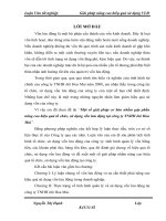
Let’s assume, you have received a rectangle as an XREFed background plan that is rotated at some
unknown angle (See fig 1) and you need to work on the overlay plan, for instance input text notes, draw
ductwork, etc... The problem is: it’s hard to do all that at an angle and align them to the background
plan. Therefore, you need the plan to show at a 0⁰angle without changing the coordinate (x,y,z) of the
original background. Keep in mind that the background should not be rotated as other trades are using
it as is.
Figure 1
© 2009 - 2LearnCAD.com - All rights reserved
Follow these Steps:
1. Type UCS in the command prompt
2. Select Named.
3. 3point and select 3 corners of the rectangle (see fig. 2)
3
2
1
Figure 2
© 2009 - 2LearnCAD.com - All rights reserved
4. Type UCSMAN.
5. On the UCS list, rename the Unnamed (double click) to whatever you want. For example
UCS90 and that would be your custom view.
6. Click OK to finish (see fig. 3).
Figure 3
© 2009 - 2LearnCAD.com - All rights reserved
7. Type PLAN.
8. Select Current or UCS to input the named view that you have just created.
The view should look like your custom view and you are ready to work (see fig.4).
Figure 4
© 2009 - 2LearnCAD.com - All rights reserved
Now look what happens when you type PLAN and select WORLD in the command line (See fig.5).
Figure 5
The original background stays the same. All your texts and work follow the unknown rotation of the
background.
If you need any further help, contact me using the contact page or visit the discussion forum
site />
© 2009 - 2LearnCAD.com - All rights reserved
Creating a fillet:
A fillet connects two objects with an arc that is tangent to the objects.
Method 1:
1.
2.
3.
4.
5.
Select the fillet symbol
from the modify menu.
Type R to specify the fillet radius.
Enter the radius
Select the first and second intersected line, object or polyline you want to fillet.
Hit Enter.
Method 2:
1.
2.
3.
4.
5.
Type FILLET or F in the command line.
Type R to specify the fillet radius.
Enter the radius
Select the first and second intersected line, object or polyline you want to fillet.
Hit Enter.
If you need any further help, contact me using the contact page or visit the discussion forum
site />
© 2009 - 2LearnCAD.com - All rights reserved
XREF – AutoCAD tutorial:
Xref is the most useful command from AutoCAD. If you are going to use the software for work
or you are looking to advance further, you will need to know how to use the xref command. It is
absolutely necessary. And I will show you why.
Xref is used to cross reference plans and objects because you want to minimize repetitions,
maximize consistency, save time and increase productivity.
Now, let us become more practical here. Let us assume you have three drawings. I will call them
sheet 1, sheet 2 and sheet 3 (see images below).
Sheet 1 shows a rectangle. But it could be anything else. The two other sheets have circles, etc.,
but they both have one thing in common: a rectangle. So instead of drawing that rectangle twice,
it would be wise to draw it once and xref it to both drawings. Some of you might think: What if I
draw it once and then copy it to each drawing?
If you copy the drawing you will have to copy it again if you want to make changes to that
rectangle. Let us say you want to make it larger or want to chamfer the edges. Do you want to
copy again? Or do you want to just change the xref and that is it.
The idea here is to reduce steps and time by drawing anything in common once. And that is
when the xref comes in handy.
© 2009 - 2LearnCAD.com - All rights reserved
There are two types of xrefs: Overlay and Attachment.
Overlay: only brings what you draw inside that xref sheet. No other dependent. In other words: if
you were to look at a tree diagram, it only goes one level deep (see image above on the left).
Attachment xrefs bring unlimited dependent xrefs and levels (see image above on the right).
Steps:
1.
2.
3.
4.
5.
6.
7.
8.
Type XREF at the command line to bring the dialogue box.
Right click and select Attach DWG.
Browse for the drawing you want to xref.
Select Open.
Pick Overlay or Attachment.
For the path, choose Full path for this tutorial.
For insertion point, scale and rotation: leave them unchecked for this tutorial.
Click OK and close the dialogue box.
© 2009 - 2LearnCAD.com - All rights reserved
Your xref drawing should be inserted inside the current drawing like the above image.
If you need any further help, contact me using the contact page or visit the discussion forum
site />
© 2009 - 2LearnCAD.com - All rights reserved
CAD
Layers – AutoCAD tutorial
The Layer command is a very important tool of AutoCAD. It lets you create layers to separate
your drawing objects. Layers are used to group, change the visibility and to control objects.
Each layer you create has its own associated properties that are unique to that layer. A list of
things you can do using layers:
•
•
•
•
•
•
•
•
Control objects by locking and unlocking layers so they are not accidentally modified.
Allow layers to be plotted or not.
Create as many layers as you want.
Group layers by colors, line types, names, etc... Also, you can create a group filter inside
the layer manager that can be saved within the drawings so other sharing users can use it
later.
Isolate layers and objects with the same properties in the drawing space. For example,
you want to show only walls and hide all doors.
Change the visibility of drawing layouts.
Turn on or off, freeze or thaw layers in model space or in the viewport layouts in paper
space.
Globally change object properties.
Steps to create a layer:
1. Type LAYER in the command line or select
from the layer toolbar.
2. By default AutoCAD will name the layer “layer1”.
3. Double click and rename it.
3
4
4
© 2009 ‐ 2LearnCAD.com ‐ All rights reserved
4
4. In the right column you can assign color, line type to the layer, freeze or thaw it.
5. Select the object in the drawing to which the layer will be assigned.
6. Click on the layer icon bar and select the appropriate layer.
5
6
Filters
Filters are good if you have multiple layers and you want to see certain layers with common
properties. For example, you can filter all layers that have the color blue or names including the
word “HVAC”.
To create a new filter:
1. Click on the very first button on the top left side above the tree navigation and renamed
it.
1
© 2009 ‐ 2LearnCAD.com ‐ All rights reserved
Within the filter dialogue you can double click below any column. For example, you want to
create a filter for all layers with the color blue.
2. Double click below the color column and select the blue color.
2
You can use the layer group filter to group layers that you define regardless of their properties.
© 2009 ‐ 2LearnCAD.com ‐ All rights reserved
Group Filter
To create a new group filter:
1. Click on the second button on the top left side above the tree navigation.
1
2
2. Drag the layers you want to group from the right side to the group filter on the left.
We only covered a few procedures, but there are many more advantages for using layers.
If you need any further help, contact me using the contact page or visit the discussion forum
site />
© 2009 ‐ 2LearnCAD.com ‐ All rights reserved
Creating an Array of objects
The array command in AutoCAD is used to make multiple copies of objects. Although you can
use the copy command to duplicate objects, the array command is more flexible and precise. One
advantage of using the array command is that it allows you to copy objects in a defined angle and
exact number of copies. Therefore, you can create array in various pattern. For example, you can
show multiple objects in a row, column, or irregular pattern such as a spiral. Let’s look at a few
examples below:
To create an array of objects follow the steps below.
Rectangular array
1.
2.
3.
4.
5.
6.
7.
8.
Type Array in the command line or select
from the modify toolbar.
Select the object you would like to array.
Input the number of rows. (negative number for downward array)
Input the number of columns. (negative number will point array to the left)
Pick or input the distance for the Row offset.
Pick or input the distance for the Column offset.
Enter the Angle for the array. (Use the default 0 degree).
Select the Preview button to see the sample array before you hit the Ok button. You can
accept the array or modify it. (Optional step).
See the figure below for visual step by step instructions.
© 2009 - 2LearnCAD.com - All rights reserved
3
2
4
5
6
7
8
Polar array
1.
2.
3.
4.
5.
6.
7.
8.
Type Array in the command line or select
from the modify toolbar.
Select the object you would like to array.
Enter or select the center point of rotation for the object.
Select a method of array. (3 methods to choose from see terms definitions below).
Enter the number of items to array. (Methods 1 and 2).
Enter the array angle. (Methods 1 and 3).
Enter the angle between the objects. (Methods 2 and 3).
Make sure to check “Rotate items as copied” if you would like to copy the objects as
selected.
9. For Object base point use the default selected. (Optional step).
10. Select the Preview button to see the sample array before you hit the Ok button. You can
accept the array or modify it. (Optional step).
See the figure below for visual step by step instructions.
© 2009 - 2LearnCAD.com - All rights reserved
2
3
4
5
6
7
10
0
8
9
Terms definitions:
Rows and columns: where you enter the number of rows and columns of objects. There is a
maximum number of rows and columns that can be entered. If you want to override that number
you can always do that by typing (setenv “MaxArray “####”) in the command prompt. Where
### is the new maximum number you would like.
Method of array: There are three (3) ways you can array objects.
(1) Total number of items & Angle to fill. This method will automatically calculate the
angle between the items based on the number of items and angle to fill.
(2) Total number of items & Angle between items. This will automatically calculate the
angle to fill the array based on the number of items.
(3) Angle to fill & Angle between items. This will automatically calculate the number of
items for you based on your input angle to fill and angle between the items.
© 2009 - 2LearnCAD.com - All rights reserved
Base point: is the reference point where AutoCAD will rotate the object. By default, depending
on the shape, the base point is already set. For example, a circle, an ellipse, or an arc, they all
have a default base point at the center, but you can manually specify a different point.
If you need any further help, please contact me using the contact page or visit the discussion
forum site />
© 2009 - 2LearnCAD.com - All rights reserved
CAD table – AutoCAD tutorial
Although working with tables in Microsoft Excel is easier and more convenient than the table
features in AutoCAD, sometimes you might want to create just a quick small table in AutoCAD.
The table will look as if you were to draw it by drawing lines in CAD.
When creating the table you have different options to choose from. You can start from:
•
•
•
Empty cell table: Normal blank CAD table.
From a data link: CAD table linked to an Excel data sheet and the table will
automatically be updated when the Excel data is changed.
From object data in the drawing (Data Extraction): table made from selected object
data in the current drawing.
To create a simple table, follow these simple steps below:
Steps to create a simple table:
1. Type “TABLE” in the command line or select
from the Draw toolbar.
2. Select “Standard” for table style unless you have a custom or template table already
made.
3. Select “Start from empty table”.
4. Specify an insertion point or specify a window where you want the table to be located in
drawing.
5. Enter the number column.
6. Specify the column width.
7. Enter the number of rows.
8. Specify the row height.
9. Set the styles for the rows. Choose in which row you want the header, title and data to be
placed.
See figure below.
© 2009 - 2LearnCAD.com - All rights reserved
2
4
3
5
6
7
8
9
Steps to create a simple table from a data link:
1.
2.
3.
4.
5.
6.
7.
8.
9.
Type “TABLE” in the command line or select
from the Draw toolbar.
Select the “From a data link“ for insert options.
Click the data link manager icon to launch the manager dialogue.
Select “Create a new Excel Data Link”.
Enter a name for your linked data.
Browse for the Excel data file location.
Select the excel file you wish to link.
Click ”Open”.
Choose whether you want to link the entire sheet, a named range or a range from the
sheet.
10. Check the “Preview” box to see the table you are about to link.
© 2009 - 2LearnCAD.com - All rights reserved
2
4
3
5
6
7
8
© 2009 - 2LearnCAD.com - All rights reserved