Physiological fluid mechanics lecture
Bạn đang xem bản rút gọn của tài liệu. Xem và tải ngay bản đầy đủ của tài liệu tại đây (5.12 MB, 130 trang )
Physiological Fluid Mechanics
Jennifer Siggers
Department of Bioengineering
Imperial College London, London, UK
September 2009
Jennifer Siggers (Imperial College London)
Physiological Fluid Mechanics
September 2009
1 / 166
Acknowledgements
I am very much indebted to the following people, who have graciously given me their time,
pictures and other material that has been very helpful in preparing these notes:
Dr Rodolfo Repetto, University of L’Aquila, Italy
Prof Kim Parker, Imperial College London,UK
Dr Jonathan Mestel, Imperial College London, UK
Prof Timothy Secomb, University of Arizona, USA
Prof Matthias Heil, University of Manchester,UK
Jennifer Siggers (Imperial College London)
Physiological Fluid Mechanics
September 2009
2 / 166
Table of contents
1
Anatomy of the cardiovascular system
2
Model of a bifurcation
3
Reynolds Transport Theorem
4
Poiseuille flow
5
Beyond Poiseuille flow
6
Lubrication Theory
7
More about the cardiovascular system
8
Wave intensity analysis
9
Further reading
Jennifer Siggers (Imperial College London)
Physiological Fluid Mechanics
September 2009
3 / 166
Outline
In this course, I will describe some of the many phenomena in physiology that can be
analysed using fluid mechanical techniques.
Most research in this area has focussed on blood flow, and in this course I will focus on this.
However, many of the techniques are quite general, and may be applied to many different
systems (physiological or non-physiological).
Due to the short amount of time, I will only be able to give you a brief flavour of the
research. If you are interested, I would recommend you read further, as there are several
excellent books on the subject, some of which are listed on Page 130.
Jennifer Siggers (Imperial College London)
Physiological Fluid Mechanics
September 2009
4 / 166
Anatomy of the cardiovascular system
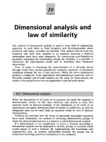
The cardiovascular system
The main function of the
cardiovascular system is to
transport oxygen, carbon dioxide
and nutrients between different
parts of the body.
It consists of a highly branched
network of vessels and the heart,
which acts as a pump.
Figure: ‘The Vein Man’ De humani corporis
fabrica (On the Workings of the Human
Body) (1543) by Andreas Vesalius
(1514-1564). Working before Harvey’s
discovery of the circulation of blood,
Vesalius believed that the veins were the
most important blood vessels responsible for
taking blood from the liver where it was
made to the tissues where it was consumed.
Most of the vessels in his illustration are
actually arteries. Although inaccurate in
many details it gives an excellent impression
of the complexity of the arterial system.
Jennifer Siggers (Imperial College London)
Physiological Fluid Mechanics
September 2009
5 / 166
Anatomy of the cardiovascular system
The cardiovascular system
For a blood particle that starts in the left
side of the heart, its journey around the
cardiovascular system is as follows:
Left side of heart → systemic
arteries → capillaries → systemic
veins → right side of heart →
pulmonary system (lungs) → left
side of heart → . . . .
Vessels:
systemic arteries, containing about 20% of
the blood,
systemic veins, containing about 54% of the
blood,
pulmonary circulation, containing about 14%
of the blood,
capillaries, containing a small fraction of the
blood,
and the heart contains about 12% (varies
during heart cycle) (Noordergraaf, 1978).
Figure: Sketch of the cardiovascular system (Ottesen,
Olufsen & Larsen, SIAM
Mon. Math. Mod. Comp., 2004).
Jennifer Siggers (Imperial College London)
Physiological Fluid Mechanics
September 2009
6 / 166
Anatomy of the cardiovascular system
Arteries
Arteries carry blood away from the heart. There are three
groups:
The systemic arteries carry oxygenated blood to the
organs of the body.
The aorta is the largest artery, coming directly out of
the heart and running down the torso. It has a large
arch (the aortic arch) just above the heart (turns
through ∼ 180◦ ) and many bifurcations (points where
the parent artery splits to feed two daughter arteries).
Other systemic arteries are the coronary, carotid, renal,
hepatic, subclavian, brachial, iliac, mesenteric and
femoral arteries and the circle of Willis. Exercise: Do
you know where all these arteries are located?
Figure: Schematic diagram showing the
major systemic arteries in the dog, by Caro,
Pedley, Schroter & Seed (1978).
Jennifer Siggers (Imperial College London)
Exercise: What is special about the pulmonary
arteries? The same special thing is true of the
umbilical artery, which carries blood from a
developing foetus towards the placenta. Why do you
think this happens?
Physiological Fluid Mechanics
September 2009
7 / 166
Anatomy of the cardiovascular system
Anatomy of the heart
The heart is the pump of the circulatory system, i.e. it is the source of energy that makes the
blood flow.
The heart may be thought of as
two pumps in series. Blood passes
...
. . . from the venous system
...
. . . into the atriuma
(low-pressure chamber), . . .
. . . through a non-return
valve . . .
. . . into the ventricle
(high-pressure chamber), . . .
. . . and through another
non-return valve . . .
. . . into the arterial system.
a In these notes, I have tried to highlight
Figure: Diagram of heart, showing the major structures, by Ottesen et in colour important technical terms that you
should be familiar with. Green highlighting is
al., 2004).
used to emphasise terms that are defined
elsewhere in these notes, while red
highlighting emphasises terms as they are
being defined.
Jennifer Siggers (Imperial College London)
Physiological Fluid Mechanics
September 2009
8 / 166
Anatomy of the cardiovascular system
Anatomy of the heart
The cardiac muscle structure
Figure: Muscle fibre orientation in wall of the left ventricle
(from Caro et al., 1978).
The walls of the heart are composed of
myocardial tissue.
Myocardial tissue is made up of fibres that can
withstand tension in the axial direction (along
their length).
The fibres are arranged in layers. The orientation
rotates gradually as the layers are traversed.
Figure: Arrangement of the muscle fibres in
wall of the left ventricle.
Jennifer Siggers (Imperial College London)
This arrangement makes the wall very strong in
every direction.
Physiological Fluid Mechanics
September 2009
9 / 166
Anatomy of the cardiovascular system
Other possible arrangements of the cardiovascular system
Figure: Sketch illustrating different types of heart. The top row shows a linear heart (e.g. a snail heart), and
the bottom row shows a looped heart, which is the type mammals have, by Kilner et al., Nature (2000).
Question: Do you think humans have a better arrangement?
Jennifer Siggers (Imperial College London)
Physiological Fluid Mechanics
September 2009
10 / 166
Anatomy of the cardiovascular system
Structure of the arterial walls
The wall has three layers:
Tunica intima. Innermost layer, a few
microns thick. Composed of endothelial
cells and their basal lamina. The
endothelial cells act as a barrier between
the blood and the wall.
Tunica media. Middle layer, separated from
the intima by the internal elastic lamina.
Composed of smooth muscle cells, elastin,
collagen and proteoglycans and determines
the elastic properties of the wall.
Figure: Histological section of an arterial wall from
Ethier & Simmons (2007).
Jennifer Siggers (Imperial College London)
Tunica adventitia. Outer layer, separated
from the media by the outer elastic lamina.
A loose connective tissue containing
collagen, nerves, fibroblasts and elastic
fibres. In large arteries this also contains
the vasa vasorum – a network of vessels
providing nutrition to the outer regions of
the artery wall.
Physiological Fluid Mechanics
September 2009
11 / 166
Anatomy of the cardiovascular system
The capillaries
Capillary walls are also made of endothelial cells.
The endothelial cells have gaps between them (unlike in the arteries), so that plasma can
leak through, while the red blood cells remain in the arteries.
Oxygen and nutrients are convected and diffused from the capillaries into the target tissues.
In the tissues, oxygen is converted to carbon dioxide.
This releases energy, which is used by the cells to perform their functions.
Jennifer Siggers (Imperial College London)
Physiological Fluid Mechanics
September 2009
12 / 166
Anatomy of the cardiovascular system
The capillaries
Figure: Pictures of the capillaries, by Gaudio et al., J. Anat. (1993).
Jennifer Siggers (Imperial College London)
Physiological Fluid Mechanics
September 2009
13 / 166
Model of a bifurcation
Introduction to the problem
Contents of this section
Anatomy of the cardiovascular system
Model of a bifurcation
Introduction to the problem
Mass conservation
Momentum conservation
Related Exercise
3 Reynolds Transport Theorem
4 Poiseuille flow
5 Beyond Poiseuille flow
1. Non-axisymmetric flow
2. Non-fully-developed flow
3. Arterial curvature
4. Unsteady flow
5. Non-Newtonian flow
6 Lubrication Theory
7 More about the cardiovascular system
The multitude of vessels
Pressure measurement
Cardiac power
Pressure in different locations in the cardiovascular system
Calculation of wall tension
Pressure–area relationships
Windkessel model
8 Wave intensity analysis
Foundations
Jennifer Siggers (Imperial College London)
Physiological Fluid Mechanics
1
2
September 2009
14 / 166
Model of a bifurcation
Introduction to the problem
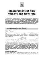
Model of a bifurcation: Introduction to the problem
A0 = 1.5 × 10⁻⁴ m2
u0 = 1 m/s
p0 = 1.2 × 10⁴ Pa
A1 = 1 × 10⁻⁴ m2
u1
p1 = 1 × 10⁴ Pa
θ = 60◦
A2 = 1 × 10⁻⁴ m2
u2
p2 = 1 × 10⁴ Pa
j
i
Figure: Schematic diagram of symmetrical bifurcation.
We study the bifurcation (splitting) of an artery shown in the figure. The cross-sectional areas of
the vessels (A∗ ), blood velocities (u∗ ) and blood pressures (p∗ ) are given and the density of the
blood (mass per unit volume) is given by ρ = 1000 kg/m3 . We will find:
The velocities u1 and u2 of blood in the daughter vessels.
The tethering force that holds the section of artery in place (provided by the surrounding
tissue and neighbouring parts of the arterial wall).
Jennifer Siggers (Imperial College London)
Physiological Fluid Mechanics
September 2009
15 / 166
Model of a bifurcation
Introduction to the problem
Model of a bifurcation: Simplifying assumptions
The bifurcation is symmetric, so the flows in the two daughter vessels are identical (u1 = u2 ).
The vessels are rigid, that is the walls do not deform.
The blood is:
incompressible, that is the density ρ of the blood (mass per unit volume) is constant, and
inviscid, that is there are no viscous forces.
steady , that is, it does not change with time.
The flow is:
uniform, that is the velocities u0 , u1 and u2 at the inlets and outlets are constant (rather than
functions of the position), and
axial, that is the direction of the velocity is along the tube and perpendicular to the surfaces.
These assumptions simplify the problem enormously, but they are only valid in some cases. Even
so, there are cases in which the following analysis yields an answer close to reality.
Jennifer Siggers (Imperial College London)
Physiological Fluid Mechanics
September 2009
16 / 166
Model of a bifurcation
Introduction to the problem
General principles used for analysis
To analyse the flow we will use two important general principles:
Mass conservation: The total amount of mass in the system remains fixed (mass cannot be
created or destroyed).
Momentum conservation: The total amount of momentum in the system changes as a
result of forces acting upon it. Newton’s second law tells us that the rate of change of
momentum equals the force. If no force is acting then the momentum stays constant.
These principles are used in some form or another for most problems in fluid mechanics.
We can apply these conservation laws to a control volume – a particular region of a fluid. The
forces acting on the fluid can be classified into:
Surface forces: Pressure and stress forces that act at the surface of the fluid. (Stress forces
arise in viscous fluids due to interaction of the fluid with the boundary.)
Body forces: Forces that act over the interior of the fluid, for example we often consider
gravity and viscous forces.
Jennifer Siggers (Imperial College London)
Physiological Fluid Mechanics
September 2009
17 / 166
Model of a bifurcation
Mass conservation
Method to apply mass conservation
Choose a control volume. In this case, we choose the control volume to be all the blood in
the region shown in the diagram.
Find the mass flux into the control volume (this has dimensions of mass per unit time). In
this case it is the flux m
˙ 0 into the parent artery.
Find the mass flux out of the control volume. In this case it is the sum of the two (identical)
fluxes m
˙ 1 and m
˙ 1 out of the daughter arteries.
The flux in must equal the flux out (this is mass conservation). In this case m
˙ 0 = 2m
˙ 1,
which we can use to find the velocity u1 in the daughter arteries.
Note: in this case the mass inside the control volume is constant because:
The volume of the control volume is constant, because the arteries are rigid.
The blood is incompressible, meaning its density (mass per unit volume) is constant (at any
point and at any time).
In some problems the mass in the control volume changes in time. We account for this using the
rule:
(Mass flux in) = (Mass flux out) + (Net rate of increase of mass in control volume).
(1)
Equation (1) is true in all situations.
Jennifer Siggers (Imperial College London)
Physiological Fluid Mechanics
September 2009
18 / 166
Model of a bifurcation
Mass conservation
Application of mass conservation
To find the mass flux into the parent artery:
Every unit of time, a length u0 of blood flows into the artery.
Therefore, every unit of time, a volume A0 u0 of blood flows into the artery (this is the
volume flux Q0 – dimensions volume per unit time).
Therefore, every unit of time, a mass ρA0 u0 of blood flows into the artery. This is the mass
flux m
˙ 0 through the parent artery (dimensions mass divided by time).
Similarly the mass flux out of each of the daughter arteries is m
˙ 1 = ρA1 u1 . Mass conservation
implies:
A0
u0 = 0.75 m/s.
(2)
m
˙ 0 = 2m
˙ 1 ⇒ ρA0 u0 = 2ρA1 u1 ⇒ u1 =
2A1
Note: the formula m
˙ = ρAu gives the mass flux of a fluid across any surface, provided that:
The fluid is incompressible.
The flow is uniform and perpendicular to the surface.
Jennifer Siggers (Imperial College London)
Physiological Fluid Mechanics
September 2009
19 / 166
Model of a bifurcation
Momentum conservation
Method to apply momentum conservation
Find the momentum flux into the control volume (this is a vector quantity and has
dimensions MLT −2 , momentum per unit time, the same dimensions as force). In this case it
˙ 0 into the parent artery.
is the flux M
Find the momentum flux out of the control volume. In this case it is the sum of the two
˙ 1 and M
˙ 2 out of the daughter arteries (note that M
˙1=M
˙ 2 since M
˙ 1 and M
˙ 2 point
fluxes M
in different directions).
Find the resultant force acting on the fluid in the control volume. In this case the force
comes from pressure forces acting on the sides and ends of the vessels (we are neglecting
gravitational, viscous and stress forces).
Jennifer Siggers (Imperial College London)
Physiological Fluid Mechanics
September 2009
20 / 166
Model of a bifurcation
Momentum conservation
Method to apply momentum conservation (ctd)
Conservation of momentum implies:
(Momentum flux out)−(Momentum flux in) = (Forces acting on fluid in control volume),
(3)
Note: The formula (3) is only true for steady flows, that is flows that do not depend on
time. If the flow is time-dependent we must account for the rate of change of momentum in
the control volume too:
(Momentum flux out) − (Momentum flux in)
+ (Rate of increase of momentum within control volume)
= (Forces acting on fluid in control volume).
Jennifer Siggers (Imperial College London)
Physiological Fluid Mechanics
September 2009
(4)
21 / 166
Model of a bifurcation
Momentum conservation
Application of momentum conservation
In the case of our bifurcation, the forces acting on the blood in the control volume are the
pressure forces on the ends of the blood in the control volume (which we can calculate) and
the pressure forces from the walls of the arteries on the blood in the control volume (which is
not easy to find, so we eliminate it). Equation (3) gives
˙ 1+M
˙ 2−M
˙ 0 = (Pressure force on ends of blood in CV)
M
+ (Pressures force from walls on blood).
(5)
The force exerted by the blood on the walls is equal and opposite (Newton’s third law):
(Pressure force of blood on walls) = −(Force from walls on blood)
(6)
And since the walls are in equilibrium the resultant force acting on the walls must zero (the
rest of the force is supplied by the tethering force:
(Resultant force on walls) = (Pressure force of blood on walls) + (Tethering force) = 0.
(7)
Therefore
(Tethering force) = −(Pressure force of blood on walls)
= (Pressure force from walls on blood)
˙ 1+M
˙ 2−M
˙ 0 − (Pressure force on ends of blood in CV).
=M
Jennifer Siggers (Imperial College London)
Physiological Fluid Mechanics
September 2009
(8)
22 / 166
Model of a bifurcation
Momentum conservation
Application of momentum conservation (ctd)
We now use Equation (8) to calculate the tethering force.
˙ 0, M
˙ 1, M
˙ 2 , and the pressure forces on the ends of
We need to find the momentum fluxes M
the parent and daughter vessels.
˙ 0 . As noted before, every unit of time a volume A0 u0 of blood enters the
First we find M
parent vessel. This blood has momentum ρu0 per unit volume. Therefore the momentum
flux has magnitude (A0 u0 )(ρu0 ) = ρA0 u02 , and it points in the same direction as the velocity
vector u0 (note that, by definition, u0 is the magnitude of u0 ). Hence
˙ 0 = ρA0 u0 u0 = ρA0 u 2 i
M
0
(9)
(where i is the unit vector in the axial direction).
˙ = ρAuu is generally true as long as the blood is incompressible and the
Note: the formula M
flow is uniform and perpendicular to the surface.
Similarly
˙ 1 = ρA1 u12 (i cos θ + j sin θ),
M
˙ 2 = ρA1 u12 (i cos θ − j sin θ),
M
(10)
(where j is the unit vector perpendicular to i in the plane of the bifurcation), and therefore
`
´
˙ 1+M
˙ 2−M
˙ 0 = ρ 2A1 u 2 cos θ − A0 u 2 i
M
(11)
1
0
Jennifer Siggers (Imperial College London)
Physiological Fluid Mechanics
September 2009
23 / 166
Model of a bifurcation
Momentum conservation
Application of momentum conservation (ctd)
The pressure forces are given by the formula (Force) = (Pressure) × (Area) and act in the
direction normal to the surface. Therefore the forces are
p0 A0 i,
−p1 A1 (i cos θ + j sin θ) ,
−p1 A1 (i cos θ − j sin θ) ,
(12)
on the ends of the parent and two daughter vessels respectively. The resultant pressure force
is the sum of these three:
(Pressure force on ends of blood in CV) = (p0 A0 − 2p1 A1 cos θ) i
(13)
Substituting in Equation (8) we obtain
`
`
´´
(Tethering force) = − (p0 A0 − 2p1 A1 cos θ) + ρ 2A1 u12 cos θ − A0 u02 i = −0.89375i N.
(14)
Jennifer Siggers (Imperial College London)
Physiological Fluid Mechanics
September 2009
24 / 166
Model of a bifurcation
Momentum conservation
Discussion of the model of a bifurcation
We have shown that the velocity in the daughter vessels is 0.75 m/s and the tethering force is
about 0.89 N in the direction opposing the flow. The tethering force arises because of the change
in total momentum at the bifurcation.
There is no dependence upon the lengths of the parent and daughter vessels. This is
because, away from the bifurcation, the vessels are symmetrical, so the pressure forces cancel
our around the cross section.
If viscosity were included, the tethering force would depend on the lengths because the walls
would exert stress forces due to the interaction with the fluid all along their length. The
stress forces all act in the same direction (in the direction opposing the flow) and do not
cancel out (unlike the pressure forces). Using a viscous fluid model of the blood would also
mean that the flow develops a profile (the velocity is no longer uniform over the cross
section). We will investigate this further in the next section.
If gravity is included it will also change the tethering force. In this case the weight of the
fluid and the weight of the walls should be added on to the force.
Jennifer Siggers (Imperial College London)
Physiological Fluid Mechanics
September 2009
25 / 166