STEP 7 system function
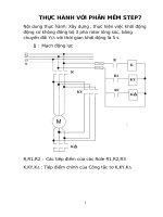
Bạn đang xem bản rút gọn của tài liệu. Xem và tải ngay bản đầy đủ của tài liệu tại đây (2.57 MB, 832 trang )
Organization Blocks
1
Common Parameters for
SFCs
2
Copy and Block Functions
3
SFCs for Controlling
Program Execution
4
SFCs for Handling the
System Clock
5
SFCs for Handling Run-Time
Meters
6
Volume 1/2
SFCs/SFBs for Transferring
Data Records
7
Reference Manual
DPV1 SFBs According to
PNO AK 1131
8
SFCs for Handling
Time-of-Day Interrupts
9
SFCs for Handling
Time-Delay Interrupts
10
SFCs for Handling
Synchronous Errors
11
SFCs for Handling Interrupts
and Asynchronous Errors
12
SFCs for Diagnostics
13
SIMATIC
System Software for S7-300/400
System and Standard Functions
This manual is part of the documentation package
with the order number:
6ES7810-4CA10-8BW1
SFCs and SFBs for Updating
the Process Image and
Processing Bit Fields
14
System Functions for
Addressing Modules
15
SFCs for Distributed I/Os or
PROFINET IO
16
PROFINET
17
SFCs and SFBs for
PROFINET CPUs
18
05/2010
A5E02789976-01
Legal information
Warning notice system
This manual contains notices you have to observe in order to ensure your personal safety, as well as to prevent
damage to property. The notices referring to your personal safety are highlighted in the manual by a safety alert
symbol, notices referring only to property damage have no safety alert symbol. These notices shown below are
graded according to the degree of danger.
DANGER
indicates that death or severe personal injury will result if proper precautions are not taken.
WARNING
indicates that death or severe personal injury may result if proper precautions are not taken.
CAUTION
with a safety alert symbol, indicates that minor personal injury can result if proper precautions are not taken.
CAUTION
without a safety alert symbol, indicates that property damage can result if proper precautions are not taken.
NOTICE
indicates that an unintended result or situation can occur if the corresponding information is not taken into
account.
If more than one degree of danger is present, the warning notice representing the highest degree of danger will
be used. A notice warning of injury to persons with a safety alert symbol may also include a warning relating to
property damage.
Qualified Personnel
The product/system described in this documentation may be operated only by personnel qualified for the specific
task in accordance with the relevant documentation for the specific task, in particular its warning notices and
safety instructions. Qualified personnel are those who, based on their training and experience, are capable of
identifying risks and avoiding potential hazards when working with these products/systems.
Proper use of Siemens products
Note the following:
WARNING
Siemens products may only be used for the applications described in the catalog and in the relevant technical
documentation. If products and components from other manufacturers are used, these must be recommended
or approved by Siemens. Proper transport, storage, installation, assembly, commissioning, operation and
maintenance are required to ensure that the products operate safely and without any problems. The permissible
ambient conditions must be adhered to. The information in the relevant documentation must be observed.
Trademarks
All names identified by ® are registered trademarks of the Siemens AG. The remaining trademarks in this
publication may be trademarks whose use by third parties for their own purposes could violate the rights of the
owner.
Disclaimer of Liability
We have reviewed the contents of this publication to ensure consistency with the hardware and software
described. Since variance cannot be precluded entirely, we cannot guarantee full consistency. However, the
information in this publication is reviewed regularly and any necessary corrections are included in subsequent
editions.
Siemens AG
Industry Sector
Postfach 48 48
90026 NÜRNBERG
GERMANY
A5E02789976-01
Ⓟ 02/2010
Copyright © Siemens AG 2010.
Technical data subject to change
Preface
Purpose
This manual provides you with a comprehensive overview of the organization blocks (OB), system
functions (SFC), system and standard function blocks (SFC), and IEC functions contained in the
operating systems of the CPUs of the S7-300 and S7-400, diagnostic data, system status lists (SZL),
and events.
Note
Refer to the reference section of the "S7-300 Automation System CPU Specifications: CPU 31xC and
CPU 31x" and "S7-300 Automation System CPU Specifications: CPU 312IFM - 318-2 DP“ /70/ or the
"Automation System S7-400: CPU Specifications" reference manual /101/ or the Instruction
List: S7-400 Programmable Controller /102/ (whichever version applies to your CPU) for details of
which of these functions and blocks are available on which CPU. The properties of the CFBs and the
S7 signaling functions for specific CPUs are described in /70/ and /101/.
For information about the CPU operating systems, program design, and the communications and
diagnostic capabilities of the CPUs, refer to the "Configuring Hardware and Communication
Connections STEP 7 V5.5" manual /234/ How to call functions and function blocks in your program is
explained in the language descriptions.
You program and assign parameters for all these functions using the STEP 7 standard software. How
to use this software is described in the "Programming with STEP 7 V5.5" manual /231/ and in the
STEP 7 online help.
Audience
This manual is intended for programmers and engineers who are familiar with controlling processes
and are responsible for writing programs for programmable logic controllers.
System Software for S7-300/400 System and Standard Functions Volume 1/2
Reference Manual, 05/2010, A5E02789976-01
3
Preface
STEP 7 Documentation Packages
The following table displays an overview of the STEP 7 documentation:
Documentation
Purpose
STEP 7 Basic Information with
Basic information for technical
6ES7810-4CA10-8BW0
personnel describing the methods of
implementing control tasks with
STEP 7 and the S7-300/400
programmable controllers.
•
Working with STEP 7,
Getting Started Manual
•
Programming with STEP 7
•
Configuring Hardware and
Communication Connections, STEP 7
•
From S5 to S7, Converter Manual
STEP 7 Reference with
4
•
Ladder Logic (LAD)/Function Block
Diagram (FBD)/Statement List (STL) for
S7-300/400 manuals
•
Standard and System Functions for
S7-300/400
Volume 1 and Volume 2
Order Number
Provides reference information and 6ES7810-4CA10-8BW1
describes the programming
languages LAD, FBD, and STL, and
standard and system functions
extending the scope of the STEP 7
basic information.
Online Helps
Purpose
Order Number
Help on STEP 7
Basic information on programming
and configuring hardware with
STEP 7 in the form of an online
help.
Part of the STEP 7
Standard software.
Reference helps on STL/LAD/FBD
Reference help on SFBs/SFCs
Reference help on Organization Blocks
Context-sensitive reference
information.
Part of the STEP 7
Standard software.
System Software for S7-300/400 System and Standard Functions Volume 1/2
Reference Manual, 05/2010, A5E02789976-01
Preface
Online Help
The manual Volume 1 and Volume 2 is complemented by an online help which is integrated in the
software. This online help is intended to provide you with detailed support when using the software.
The help system is integrated in the software via a number of interfaces:
•
There are several menu commands which you can select in the Help menu: The Contents
command opens the index for the Help on STEP 7.
•
Using Help provides detailed instructions on using the online help.
•
The context-sensitive help offers information on the current context, for example, an open dialog
box or an active window. You can open the context-sensitive help by clicking the "Help" button or
by pressing F1.
•
The status bar offers another form of context-sensitive help. It displays a short explanation for
each menu command when the mouse pointer is positioned on the menu command.
•
A brief explanation is also displayed for each icon in the toolbar when the mouse pointer is
positioned on the icon for a short time.
If you prefer to read the information from the online help in printed format, you can print out individual
help topics, books, or the entire online help.
This manual is an extract from the HTML-based Help on STEP 7. As the manual and the online help
share an almost identical structure, it is easy to switch between the manual and the online help.
Feedback on Documentation
To help us to provide the best possible documentation for you and future STEP 7 users, we need your
support. If you have any comments or suggestions relating to this manual or the online help, please
complete the questionnaire at the end of the manual and send it to the address shown. Please include
your own personal rating of the documentation.
Other Manuals
The various S7-300 and S7-400 CPUs and the S7-300 and S7-400 modules are described in the
following manuals:
•
For the S7-300 programmable logic controller, refer to the manuals: "PLC S7-300, CPU
Specifications CPU 312 IFM to CPU 318-2 DP and S7-300 CPU 31xC and CPU 31x: Technical
specifications“ /70/, "S7-300 S7-300 Module data" /71/ and in the Instruction List /72/.
•
For the S7-400 programmable logic controller, refer to the manual:
"S7-400 Automation System: Module Data" /101/ and in the Instruction List /102/.
System Software for S7-300/400 System and Standard Functions Volume 1/2
Reference Manual, 05/2010, A5E02789976-01
5
Preface
How to Use this Manual
This manual covers the following topics:
•
Chapter 1 explains the functions of all the organization blocks.
•
Chapter 2 describes the common parameters RET_VAL, REQ and BUSY.
•
Chapters 3 to 32 describe the SFCs, SFBs and IEC-FCs.
•
The Chapters sections 33 to 36 contain a description of the structure of the diagnostic data, an
overview of the SZL-IDs, the possible events, lists of the SFCs, SFBs and FCs described in this
manual, an overview of the SDBs.
•
The bibliography contains a list of further manuals.
•
The Glossary explains important terminology.
•
The Index helps you to locate sections of text and topics quickly.
Conventions
References to other manuals and documentation are indicated by numbers in slashes /.../. These
numbers refer to the titles of manuals listed in the bibliography.
Special Note
The system functions can be interrupted. If there are any restrictions that apply to certain SFCs or
situations, these are explained in the description of the particular SFC.
Further Support
If you have any technical questions, please get in touch with your Siemens representative or
responsible agent.
You will find your contact person at:
/>You will find a guide to the technical documentation offered for the individual SIMATIC Products and
Systems at:
/>The online catalog and order system is found under:
/>
Training Centers
Siemens offers a number of training courses to familiarize you with the SIMATIC S7 automation
system. Please contact your regional training center or our central training center in D 90026
Nuremberg, Germany for details:
Internet:
6
System Software for S7-300/400 System and Standard Functions Volume 1/2
Reference Manual, 05/2010, A5E02789976-01
Preface
Technical Support
You can reach the Technical Support for all Industry Automation and Drive Technology products
•
Via the Web formula for the Support Request
/>
Additional information about our Technical Support can be found on the Internet pages
/>
Service & Support on the Internet
In addition to our documentation, we offer our Know-how online on the internet at:
/>where you will find the following:
•
The newsletter, which constantly provides you with up-to-date information on your products.
•
The right documents via our Search function in Service & Support.
•
A forum, where users and experts from all over the world exchange their experiences.
•
Your local representative for Industry Automation and Drive Technology.
Information on field service, repairs, spare parts and consulting.
System Software for S7-300/400 System and Standard Functions Volume 1/2
Reference Manual, 05/2010, A5E02789976-01
7
Preface
8
System Software for S7-300/400 System and Standard Functions Volume 1/2
Reference Manual, 05/2010, A5E02789976-01
Contents
1
Organization Blocks..................................................................................................................................13
1.1
1.2
1.3
1.4
1.5
1.6
1.7
1.8
1.9
1.10
1.11
1.12
1.13
1.14
1.15
1.16
1.17
1.18
1.19
1.20
1.21
1.22
1.23
1.24
1.25
1.26
1.27
1.28
2
Common Parameters for SFCs ................................................................................................................87
2.1
2.2
3
Overview of the Organization Blocks (OBs) ................................................................................13
Program Cycle Organization Block (OB1) ...................................................................................16
Time-of-Day Interrupt Organization Blocks (OB10 to OB17).......................................................18
Time-Delay Interrupt Organization Blocks (OB20 to OB23) ........................................................22
Cyclic Interrupt Organization Blocks (OB30 to OB38) .................................................................24
Hardware Interrupt Organization Blocks (OB40 to OB47)...........................................................26
Status Interrupt OB (OB55)..........................................................................................................28
Update Interrupt OB (OB56) ........................................................................................................32
Manufacturer Specific Interrupt OB (OB57).................................................................................36
Multicomputing Interrupt Organization Block (OB60) ..................................................................40
Synchronous Cycle Interrupt OBs (OB61 to OB64).....................................................................42
Technology Synchronization Interrupt OB (OB65) ......................................................................43
I/O Redundancy Error OB (OB70) ...............................................................................................44
CPU Redundancy Error OB (OB72) ............................................................................................46
Communication Redundancy Error OB (OB73)...........................................................................49
Time Error Organization Block (OB80) ........................................................................................50
Power Supply Error Organization Block (OB81)..........................................................................53
Diagnostic Interrupt Organization Block (OB82)..........................................................................55
Insert / Remove Module Interrupt Organization Block (OB83) ....................................................57
CPU Hardware Fault Organization Block (OB84)........................................................................61
Priority Class Error Organization Block (OB85)...........................................................................62
Rack Failure Organization Block (OB86).....................................................................................66
Communication Error Organization Block (OB87) .......................................................................71
Processing Interrupt OB (OB88) ..................................................................................................73
Background Organization Block (OB90)......................................................................................75
Startup Organization Blocks (OB100, OB101 and OB102) .........................................................77
Programming Error Organization Block (OB121) ........................................................................82
I/O Access Error Organization Block (OB122).............................................................................85
Evaluating Errors with Output Parameter RET_VAL ...................................................................87
Meaning of the Parameters REQ, RET_VAL and BUSY with Asynchronous SFCs ...................92
Copy and Block Functions .......................................................................................................................97
3.1
3.2
3.3
3.4
3.5
3.6
3.7
3.8
3.9
3.10
3.11
3.12
Copying Memory Area with SFC 20 "BLKMOV"..........................................................................97
Uninterruptible Copying of Variables with SFC 81 "UBLKMOV" ...............................................100
Initializing a Memory Area with SFC 21 "FILL" ..........................................................................102
Creating a Data Block with SFC 22 "CREAT_DB" ....................................................................105
Deleting a Data Block with SFC 23 "DEL_DB" ..........................................................................107
Testing a Data Block with SFC 24 "TEST_DB" .........................................................................109
Compressing the User Memory with SFC 25 "COMPRESS" ....................................................110
Transferring a Substitute Value to Accumulator 1 with SFC 44 "REPL_VAL" ..........................112
Generating Data Blocks in Load Memory with SFC 82 "CREA_DBL".......................................113
Reading from a Data Block In Load Memory with SFC 83 "READ_DBL" .................................116
Writing a Data Block in Load Memory with SFC 84 "WRIT_DBL".............................................118
Creating a Data Block with SFC 85 "CREA_DB".......................................................................120
System Software for S7-300/400 System and Standard Functions Volume 1/2
Reference Manual, 05/2010, A5E02789976-01
9
Contents
4
SFCs for Controlling Program Execution .............................................................................................123
4.1
4.2
4.3
4.4
4.5
4.6
5
SFCs for Handling the System Clock ....................................................................................................131
5.1
5.2
5.3
5.4
6
Reading a Data Record with SFB 52 "RDREC".........................................................................165
Writing a Data Record with SFB53 "WRREC" ...........................................................................167
Receiving an Interrupt with SFB 54 "RALRM" ...........................................................................169
Sending an Interrupt to the DP Master with SFB 75 "SALRM"..................................................187
Receiving a Data Record with SFB 73 "RCVREC"....................................................................194
Providing a Data Record with SFB 74 "PRVREC".....................................................................197
SFCs for Handling Time-of-Day Interrupts ...........................................................................................201
9.1
9.2
9.3
9.4
9.5
9.6
10
Writing and Reading Data Records ...........................................................................................145
Reading Defined Parameters with SFC 54 "RD_DPARM" ........................................................148
Reading Predefined Parameters with SFC 102 "RD_DPARA"..................................................149
Writing Dynamic Parameters with SFC 55 "WR_PARM" ..........................................................150
Writing Default Parameters with SFC 56 "WR_DPARM" ..........................................................152
Assigning Parameters to a Module with SFC 57 "PARM_MOD"...............................................153
Writing a Data Record with SFC 58 "WR_REC"........................................................................156
Reading a Data Record with SFC 59 "RD_REC" ......................................................................158
Further Error Information for SFCs 55 to 59 ..............................................................................163
Reading Predefined Parameters with SFB 81 "RD_DPAR" ......................................................163
DPV1 SFBs According to PNO AK 1131................................................................................................165
8.1
8.2
8.3
8.4
8.5
8.6
9
Runtime Meters..........................................................................................................................137
Handling Runtime meters with SFC 101 "RTM" ........................................................................139
Setting the Runtime Meter with SFC 2 "SET_RTM" ..................................................................141
Starting and Stopping a Run-time Meter with SFC 3 "CTRL_RTM" ..........................................142
Reading a Runtime Meter with SFC 4 "READ_RTM"................................................................143
Reading the System Time with SFC 64 "TIME_TCK" ...............................................................144
SFCs/SFBs for Transferring Data Records...........................................................................................145
7.1
7.2
7.3
7.4
7.5
7.6
7.7
7.8
7.9
7.10
8
Setting the TOD with SFC 0 "SET_CLK" ...................................................................................131
Reading the Time with SFC 1 "READ_CLK" .............................................................................132
Synchronizing Slave Clocks with SFC 48 "SNC_RTCB"...........................................................133
Setting the Time-of-Day and the TOD Status with SFC 100 "SET_CLKS" ...............................134
SFCs for Handling Run-Time Meters.....................................................................................................137
6.1
6.2
6.3
6.4
6.5
6.6
7
Re-triggering Cycle Time Monitoring with SFC 43 "RE_TRIGR"...............................................123
Changing the CPU to STOP with SFC 46 "STP" .......................................................................123
Delaying Execution of the User Program with SFC 47 "WAIT" .................................................124
Triggering a Multicomputing Interrupt with SFC 35 "MP_ALM" .................................................125
Controlling CiR with SFC 104 "CiR"...........................................................................................126
Activating Write-protection with SFC 109 "PROTECT" .............................................................128
Handling Time-of-Day Interrupts................................................................................................201
Characteristics of SFCs 28 to 31 ...............................................................................................202
Setting a Time-of-Day Interrupt with SFC 28 "SET_TINT" ........................................................204
Canceling a Time-of-Day Interrupt with SFC 29 "CAN_TINT"...................................................205
Activating a Time-of-Day Interrupt with SFC 30 "ACT_TINT"....................................................206
Querying a Time-of-Day Interrupt with SFC 31 "QRY_TINT" ....................................................207
System Software for S7-300/400 System and Standard Functions Volume 1/2
Reference Manual, 05/2010, A5E02789976-01
Contents
10
SFCs for Handling Time-Delay Interrupts.............................................................................................209
10.1
10.2
10.3
10.4
11
SFCs for Handling Synchronous Errors ...............................................................................................215
11.1
11.2
11.3
11.4
12
12.3
12.4
12.5
13.5
13.6
13.7
System Diagnostics ...................................................................................................................235
Reading OB Start Information with SFC 6 "RD_SINFO" ...........................................................235
Reading a System Status List or Partial List with SFC 51 "RDSYSST" ....................................238
Writing a User-Defined Diagnostic Event to the Diagnostic Buffer with
SFC 52 "WR_USMSG" ..............................................................................................................245
Determining the OB Program Runtime with SFC 78 "OB_RT"..................................................249
Diagnosis of the Current Connection Status with SFC 87 "C_DIAG"........................................254
Identifying the Bus Topology of a DP Master System with SFC 103 "DP_TOPOL"..................259
SFCs and SFBs for Updating the Process Image and Processing Bit Fields...................................263
14.1
14.2
14.3
14.4
14.5
14.6
14.7
15
Delaying and Disabling Interrupt and Asynchronous Errors......................................................227
Disabling the Processing of New Interrupts and Asynchronous Errors with
SFC 39 "DIS_IRT"......................................................................................................................229
Enabling the Processing of New Interrupts and Asynchronous Errors with
SFC 40 "EN_IRT".......................................................................................................................231
Delaying the Processing of Higher Priority Interrupts and Asynchronous Errors with
SFC 41 "DIS_AIRT" ...................................................................................................................233
Enabling the Processing of Higher Priority Interrupts and Asynchronous Errors with
SFC 42 "EN_AIRT" ....................................................................................................................234
SFCs for Diagnostics ..............................................................................................................................235
13.1
13.2
13.3
13.4
14
Masking Synchronous Errors.....................................................................................................215
Masking Synchronous Errors with SFC 36 "MSK_FLT" ............................................................223
Unmasking Synchronous Errors with SFC 37 "DMSK_FLT".....................................................224
Reading the Error Register with SFC 38 "READ_ERR" ............................................................225
SFCs for Handling Interrupts and Asynchronous Errors ...................................................................227
12.1
12.2
13
Handling Time-Delay Interrupts .................................................................................................209
Starting a Time-Delay Interrupt with SFC 32 "SRT_DINT"........................................................211
Querying a Time-Delay Interrupt with SFC 34 "QRY_DINT".....................................................212
Canceling a Time-Delay Interrupt with SFC 33 "CAN_DINT"....................................................214
Updating the Process Image Input Table with SFC 26 "UPDAT_PI" ........................................263
Updating the Process Image Output Table with SFC 27 "UPDAT_PO"....................................265
Updating the Process Image Partition Input Table in a Synchronous Cycle with
SFC 126 "SYNC_PI" ..................................................................................................................267
Updating the Process Image Partition in a Synchronous Cycle with
SFC 127 "SYNC_PO" ................................................................................................................269
Setting a Bit Field in the I/O Area with SFC 79 "SET" ...............................................................271
Resetting a Bit Field in the I/O Area with SFC 80 "RSET".........................................................272
Implementing a Sequencer with SFB 32 "DRUM" .....................................................................273
System Functions for Addressing Modules .........................................................................................277
15.1
15.2
15.3
15.4
15.5
Querying the Logical Base Address of a Module with SFC 5 "GADR_LGC" ............................277
Querying the Module Slot Belonging to a Logical Address with SFC 49 "LGC_GADR" ...........279
Querying all Logical Addresses of a Module with SFC 50 "RD_LGADR" .................................281
Determining the Start Address of a Module with SFC 70 "GEO_LOG".....................................282
Determining the Slot Belonging to a Logical Address with SFC 71 "LOG_GEO" .....................284
System Software for S7-300/400 System and Standard Functions Volume 1/2
Reference Manual, 05/2010, A5E02789976-01
11
Contents
16
SFCs for Distributed I/Os or PROFINET IO ...........................................................................................287
16.1
16.2
16.3
16.4
16.5
16.6
17
PROFINET ................................................................................................................................................313
17.1
17.2
17.3
17.4
18
Background Information on SFCs 112, 113 and 114.................................................................313
Updating the Inputs of the User Program Interface for the PROFINET CBA Component
with SFC 112 "PN_IN" ...............................................................................................................316
Updating the Outputs of the PROFINET Interface of the PROFINET CBA Component
with SFC 113 "PN_OUT" ...........................................................................................................317
Updating DP Interconnections with SFC 114 "PN_DP".............................................................318
SFCs and SFBs for PROFINET CPUs ....................................................................................................319
18.1
18.2
12
Triggering a Hardware Interrupt on the DP Master with SFC 7 "DP_PRAL".............................287
Synchronizing Groups of DP Slaves with SFC 11 "DPSYC_FR" ..............................................290
Deactivating and Activating DP Slaves/PROFINET IO Devices with SFC 12 "D_ACT_DP".....296
Reading Diagnostic Data of a DP Slave with SFC 13 "DPNRM_DG" (Slave Diagnostics) .......303
Reading Consistent Data of a DP Standard Slave//PROFINET IO Device
with SFC 14 "DPRD_DAT".........................................................................................................307
Writing Consistent Data to a DP Standard Slave/PROFINET IO Device
with SFC 15 "DPWR_DAT"........................................................................................................310
Enabling or Synchronizing User Web Pages with SFC99 "WWW" ...........................................319
Setting the IP Configuration with SFB104 "IP_CONF" ..............................................................321
System Software for S7-300/400 System and Standard Functions Volume 1/2
Reference Manual, 05/2010, A5E02789976-01
1
Organization Blocks
1.1
Overview of the Organization Blocks (OBs)
What Are Organization Blocks?
Organization Blocks (OBs) are the interface between the operating system of the CPU and the user
program. OBs are used to execute specific program sections:
•
At the startup of the CPU
•
In a cyclic or clocked execution
•
Whenever errors occur
•
Whenever hardware interrupts occur.
Organization blocks are executed according to the priority they are allocated.
Which OBs Are Available?
Not all CPUs can process all of the OBs available in STEP 7. Refer to Operations lists /72/ and /102/
to determine which OBs are included with your CPU.
System Software for S7-300/400 System and Standard Functions Volume 1/2
Reference Manual, 05/2010, A5E02789976-01
13
Organization Blocks
1.1 Overview of the Organization Blocks (OBs)
Where to Find More Information?
Refer to the online help and the following manuals for more information:
•
/70/: this manual contains the technical data that describe the capabilities of the different S7-300
CPUs.
•
/101/: this manual contains the technical data that describe the capabilities of the different S7-400
CPUs.
The following table contains the start event belonging to each OB as well as the default priority class.
14
OB
Start Event
Default Priority Class
Explanation
OB1
End of startup or end of OB1
1
Free cycle
OB10
Time-of-day interrupt 0
2
No default time specified
OB11
Time-of-day interrupt 1
2
OB12
Time-of-day interrupt 2
2
OB13
Time-of-day interrupt 3
2
OB14
Time-of-day interrupt 4
2
OB15
Time-of-day interrupt 5
2
OB16
Time-of-day interrupt 6
2
OB17
Time-of-day interrupt 7
2
OB20
Time-delay interrupt 0
3
OB21
Time-delay interrupt 1
4
OB22
Time-delay interrupt 2
5
OB23
Time-delay interrupt 3
6
OB30
Cyclic interrupt 0 (default interval: 5 s)
7
OB31
Cyclic interrupt 1 (default interval: 2 s)
8
OB32
Cyclic interrupt 2 (default interval: 1 s)
9
OB33
Cyclic interrupt 3 (default interval: 500 ms)
10
OB34
Cyclic interrupt 4 (default interval: 200 ms)
11
OB35
Cyclic interrupt 5 (default interval: 100 ms)
12
OB36
Cyclic interrupt 6 (default interval: 50 ms)
13
OB37
Cyclic interrupt 7 (default interval: 20 ms)
14
OB38
Cyclic interrupt 8 (default interval: 10 ms)
15
OB40
Hardware interrupt
0
16
OB41
Hardware interrupt
1
17
OB42
Hardware interrupt
2
18
OB43
Hardware interrupt
3
19
OB44
Hardware interrupt
4
20
OB45
Hardware interrupt
5
21
OB46
Hardware interrupt
6
22
OB47
Hardware interrupt
7
23
OB55
Status interrupt
2
OB56
Update interrupt
2
OB57
Manufacturer specific interrupt
2
OB60
SFC35 "MP_ALM" call
25
No default time specified
Cyclic interrupts
Hardware interrupts
DPV1 interrupts
Multicomputing interrupt
System Software for S7-300/400 System and Standard Functions Volume 1/2
Reference Manual, 05/2010, A5E02789976-01
Organization Blocks
1.1 Overview of the Organization Blocks (OBs)
OB
Start Event
Default Priority Class
Explanation
OB61
Synchronous Cycle Interrupt 1
25
OB62
Synchronous Cycle Interrupt 2
25
Synchronous Cycle
Interrupt
OB63
Synchronous Cycle Interrupt 3
25
OB64
Synchronous Cycle Interrupt 4
25
OB65
Technology synchronization interrupt
25
Technology
synchronization interrupt
OB70
I/O redundancy error (only in H CPUs)
25
OB72
CPU redundancy error (only in H CPUs)
28
Redundancy error
interrupts
OB73
Communication redundancy error OB (only in H
CPUs)
25
OB80
Time error
26, 28 1)
OB81
Power supply fault
26, 28 1) with S7-300,
1)
25, 28 with S7-400
and CPU 318
OB82
Diagnostic interrupt
26, 28 1) with S7-300,
1)
25, 28 with S7-400
and CPU 318
OB83
Insert/remove module interrupt
26, 28 1) with S7-300,
1)
25, 28 with S7-400
and CPU 318
OB84
CPU hardware fault
26, 28 1) with S7-300,
25, 28 1) with S7-400
and CPU 318
OB85
Program error
26, 28 1) with S7-300,
1)
25, 28 with S7-400
and CPU 318
OB86
Failure of an expansion rack, DP master system 26, 28 1) with S7-300,
1)
or station for distributed I/Os
25, 28 with S7-400
and CPU 318
OB87
Communication error
26, 28 1) with S7-300,
25, 28 1) with S7-400
and CPU 318
OB88
Processing interrupt
28
OB90
Warm or cold restart or delete a block being
executed in OB90 or load an OB90 on the CPU
or terminate OB90
29 2)
Background cycle
OB100
Warm restart
27 1)
Startup
OB101
Hot restart
27 1)
OB102
Cold restart
27 1)
OB121
Programming error
Priority of the OB
causing the error
2)
Synchronous error
interrupts
Priority of the OB
causing the error
Priority classes 27 and 28 are valid in the priority class model of the startup.
Priority class 29 corresponds to priority 0.29. This means that the background cycle has lower priority than the
free cycle.
OB122
1)
Asynchronous error
interrupts
I/O access error
System Software for S7-300/400 System and Standard Functions Volume 1/2
Reference Manual, 05/2010, A5E02789976-01
15
Organization Blocks
1.2 Program Cycle Organization Block (OB1)
1.2
Program Cycle Organization Block (OB1)
Description
The operating system of the S7 CPU executes OB1 periodically. When OB1 has been executed, the
operating system starts it again. Cyclic execution of OB1 is started after the startup has been
completed. You can call other function blocks (FBs, SFBs) or functions (FCs, SFCs) in OB1.
Understanding the Operation of OB1
OB1 has the lowest priority of all of the OBs whose run-times are monitored, in other words, all of the
other OBs except OB90 can interrupt the execution of OB1. The following events cause the operating
system to call OB1:
•
The startup is completed.
•
The execution of OB1 (the previous cycle) has finished.
When OB1 has been executed, the operating system sends global data. Before restarting OB1, the
operating system writes the process-image output table to the output modules, updates the
process-image input table and receives any global data for the CPU.
S7 monitors the maximum scan time, ensuring a maximum response time. The value for the maximum
scan time is preset to 150 ms. You can set a new value or you can restart the time monitoring
anywhere within your program with SFC43 "RE_TRIGR." If your program exceeds the maximum cycle
time for OB1, the operating system calls OB80 (time error OB); if OB80 is not programmed, the CPU
changes to the STOP mode.
Apart from monitoring the maximum scan time, it is also possible to guarantee a minimum scan time.
The operating system will delay the start of a new cycle (writing of the process image output table to
the output modules) until the minimum scan time has been reached.
Refer to the manuals /70/ and /101/ for the ranges of the parameters "maximum" and "minimum" scan
time. You change parameter settings using STEP 7.
16
System Software for S7-300/400 System and Standard Functions Volume 1/2
Reference Manual, 05/2010, A5E02789976-01
Organization Blocks
1.2 Program Cycle Organization Block (OB1)
Local Data for OB1
The following table describes the temporary (TEMP) variables for OB1. The variable names are the
default names of OB1.
Variable
Type
Description
OB1_EV_CLASS
BYTE
Event class and identifiers: B#16#11: OB1 active
OB1_SCAN_1
BYTE
•
B#16#01: completion of a warm restart
•
B#16#02: completion of a hot restart
•
B#16#03: completion of the main cycle
•
B#16#04: completion of a cold restart
•
B#16#05: first OB1 cycle of the new master CPU after
master-reserve switchover and STOP of the previous
master
OB1_PRIORITY
BYTE
Priority class 1
OB1_OB_NUMBR
BYTE
OB number (01)
OB1_RESERVED_1
BYTE
Reserved
OB1_RESERVED_2
BYTE
Reserved
OB1_PREV_CYCLE
INT
Run time of previous scan (ms)
OB1_MIN_CYCLE
INT
Minimum cycle time (ms) since the last startup
OB1_MAX_CYCLE
INT
Maximum cycle time (ms) since the last startup
OB1_DATE_TIME
DATE_AND_TIME
DATE_AND_TIME of day when the OB was called
System Software for S7-300/400 System and Standard Functions Volume 1/2
Reference Manual, 05/2010, A5E02789976-01
17
Organization Blocks
1.3 Time-of-Day Interrupt Organization Blocks (OB10 to OB17)
1.3
Time-of-Day Interrupt Organization Blocks (OB10 to OB17)
Description
STEP 7 provides up to eight OBs (OB10 to OB17) which can be run once or periodically. You can
assign parameters for CPU using SFCs or STEP 7 so that these OBs are processed at the following
intervals:
•
Once
•
Every minute
•
Hourly
•
Daily
•
Weekly
•
Monthly
•
At the end of each month
Note
For monthly execution of a time-of-day interrupt OBs, only the days 1, 2, ... 28 can be used as a
starting date.
18
System Software for S7-300/400 System and Standard Functions Volume 1/2
Reference Manual, 05/2010, A5E02789976-01
Organization Blocks
1.3 Time-of-Day Interrupt Organization Blocks (OB10 to OB17)
Understanding the Operation of Time-of-Day Interrupt OBs
To start a time-of-day interrupt, you must first set and then activate the interrupt. The three following
start possibilities exist:
•
Automatic start of the time-of-day interrupt. This occurs once you have set and then activated the
time-of-day interrupt with STEP 7. The following table shows the basic possibilities for activating a
time-of-day interrupt with STEP 7.
•
You set the time-of-day interrupt with STEP 7 and then activate it by calling SFC30 "ACT-TINT" in
your program.
•
You set the time-of-day interrupt by calling SFC28 "SET_TINT" and then activate it by calling
SFC30 "ACT_TINT."
Interval
Description
Not activated
The time-of-day interrupt is not executed, even when loaded in the CPU. It can be
activated by calling SFC30.
Activated once only
The time-of-day OB is canceled automatically after it runs the one time specified.
Your program can use SFC28 and SFC30 to reset and reactivate the OB.
Activated periodically
When the time-of-day interrupt occurs, the CPU calculates the next start time for
the time-of-day interrupt based on the current time of day and the period.
The behavior of the time-of-day interrupt when you move the clock forwards or backwards is described
in /234/.
Note
If you configure a time-of-day interrupt in such a way that the corresponding OB is to be processed once, the
DATE_AND_TIME must not be in the past (relative to the real-time clock of the CPU).
If you configure a time-of-day interrupt in such a way that the corresponding OB is to be processed periodically,
the start DATE_AND_TIME, however, are in the past, then the time-of-day interrupt will be processed the next
time it is due. This is illustrated in the following figure.
You can disable or delay and re-enable time-of-day interrupts using SFCs 39 to 42.
Preset
start time
Preset
interval
Current
time
Point at which the time-of-day
interrupt OB is first executed.
System Software for S7-300/400 System and Standard Functions Volume 1/2
Reference Manual, 05/2010, A5E02789976-01
19
Organization Blocks
1.3 Time-of-Day Interrupt Organization Blocks (OB10 to OB17)
Conditions That Affect Time-of-Day Interrupt OBs
Since a time-of-day interrupt occurs only at specified intervals, certain conditions can affect the
operation of the OB during the execution of your program. The following table shows some of these
conditions and describes the effect on the execution of the time-of-day interrupt OB.
Condition
Result
Your program calls SFC29 (CAN_TINT) and
cancels a time-of-day interrupt.
The operating system clears the start event
(DATE_AND_TIME) for the time-of-day interrupt. You must
set the start event again and activate it before the OB can
be called again.
Your program attempted to activate a time-of-day
interrupt OB, but the OB was not loaded on the
CPU.
The operating system calls OB85. If OB85 has not been
programmed (loaded on the CPU), the CPU changes to the
STOP mode.
When synchronizing or correcting the system
clock of the CPU, you set the time ahead and
skipped the start event date or time for the
time-of-day OB.
The operating system calls OB80 and encodes the number
of the time-of-day OB and the start event information in
OB80.
When synchronizing or correcting the system
clock of the CPU, the time was set back so that
the start event, date, or time for the OB is
repeated.
S7-400-CPUs and CPU 318:
If the time-of-day OB had already been activated before
the clock was set back, it is not called again.
The CPU runs through a warm or cold restart.
Any time-of-day OB that was configured by an SFC is
changed back to the configuration that was specified in
STEP 7.
The operating system then runs the time-of-day OB once,
regardless of the number of times that this OB should have
been executed. The start event information of OB80 shows
the DATE_AND_TIME that the time-of-day OB was first
skipped.
S7-300-CPUs: The time-of-day OB is executed.
If you have configured a time-of-day interrupt for a
one-time start of the corresponding OB, set it with
STEP 7, and activated it, the OB is called once after a
warm or cold restart of the operating system, if the
configured start time is in the past (relative to the real-time
clock of the CPU).
A time-of-day OB is still being executed when the
start event for the next interval occurs.
The operating system calls OB80. If OB80 is not
programmed, the CPU changes to the STOP mode.
If OB80 is loaded, both OB80 and the time-of-day interrupt
OB are first executed and then second the requested
interrupt is executed.
20
System Software for S7-300/400 System and Standard Functions Volume 1/2
Reference Manual, 05/2010, A5E02789976-01
Organization Blocks
1.3 Time-of-Day Interrupt Organization Blocks (OB10 to OB17)
Local Data for Time-of-Day Interrupt OBs
The following table describes the temporary (TEMP) variables for a time-of-day interrupt OB. The
variable names are the default names of OB10.
Variable
Type
Description
OB10_EV_CLASS
BYTE
Event class and identifiers: B#16#11 = interrupt is active
OB10_STRT_INFO
BYTE
B#16#11: start request for OB10
(B#16#12: start request for OB11)
:
:
(B#16#18: start request for OB17)
OB10_PRIORITY
BYTE
Assigned priority class; default 2
OB10_OB_NUMBR
BYTE
OB number (10 to 17)
OB10_RESERVED_1
BYTE
Reserved
OB10_RESERVED_2
BYTE
Reserved
OB10_PERIOD_EXE
WORD
The OB is executed at the specified intervals:
W#16#0000: once
W#16#0201: once every minute
W#16#0401: once hourly
W#16#1001: once daily
W#16#1201: once weekly
W#16#1401: once monthly
W#16#1801: once yearly
W#16#2001: end of month
OB10_RESERVED_3
INT
Reserved
OB10_RESERVED_4
INT
Reserved
OB10_DATE_TIME
DATE_AND_TIME
DATE_AND_TIME of day when the OB was called
System Software for S7-300/400 System and Standard Functions Volume 1/2
Reference Manual, 05/2010, A5E02789976-01
21
Organization Blocks
1.4 Time-Delay Interrupt Organization Blocks (OB20 to OB23)
1.4
Time-Delay Interrupt Organization Blocks (OB20 to OB23)
Description
S7 provides up to four OBs (OB20 to OB23) which are executed after a specified delay. Every
time-delay OB is started by calling SFC32 (SRT_DINT). The delay time is an input parameter of the
SFC.
When your program calls SFC32 (SRT_DINT), you provide the OB number, the delay time, and a
user-specific identifier. After the specified delay, the OB starts. You can also cancel the execution of a
time-delay interrupt that has not yet started.
Understanding the Operation of Time-Delay Interrupt OBs
After the delay time has expired (value in milliseconds transferred to SFC32 together with an OB
number), the operating system starts the corresponding OB.
To use the time-delay interrupts, you must perform the following tasks:
•
You must call SFC32 (SRT_DINT).
•
You must download the time-delay interrupt OB to the CPU as part of your program.
Time-delay OBs are executed only when the CPU is in the RUN mode. A warm or a cold restart clears
any start events for the time-delay OBs. If a time-delay interrupt has not started, you can use SFC33
(CAN_DINT) to cancel its execution.
The delay time has a resolution of 1 ms. A delay time that has expired can be started again
immediately. You can query the status of a delay-time interrupt using SFC34 (QRY_DINT).
The operating system calls an asynchronous error OB if one of the following events occur:
•
If the operating system attempts to start an OB that is not loaded and you specified its number
when calling SFC32 "SRT_DINT."
•
If the next start event for a time-delay interrupt occurs before the time-delay OB has been
completely executed.
You can disable or delay and re-enable delay interrupts using SFCs 39 to 42.
22
System Software for S7-300/400 System and Standard Functions Volume 1/2
Reference Manual, 05/2010, A5E02789976-01
Organization Blocks
1.4 Time-Delay Interrupt Organization Blocks (OB20 to OB23)
Local Data for Time-Delay Interrupt OBs
The following table describes the temporary (TEMP) variables for a time-delay interrupt OB. The
variable names are the default names of OB20.
Variable
Type
Description
OB20_EV_CLASS
BYTE
Event class and identifiers:
B#16#11: interrupt is active
OB20_STRT_INF
BYTE
B#16#21: start request for OB20
(B#16#22: start request for OB21)
(B#16#23: start request for OB22)
(B#16#24: start request for OB23)
OB20_PRIORITY
BYTE
Assigned priority class: default values 3 (OB20) to 6 (OB23)
OB20_OB_NUMBR
BYTE
OB number (20 to 23)
OB20_RESERVED_1
BYTE
Reserved
OB20_RESERVED_2
BYTE
Reserved
OB20_SIGN
WORD
User ID: input parameter SIGN from the call for SFC32
(SRT_DINT)
OB20_DTIME
TIME
Configured delay time in ms
OB20_DATE_TIME
DATE_AND_TIME
DATE_AND_TIME of day when the OB was called
System Software for S7-300/400 System and Standard Functions Volume 1/2
Reference Manual, 05/2010, A5E02789976-01
23
Organization Blocks
1.5 Cyclic Interrupt Organization Blocks (OB30 to OB38)
1.5
Cyclic Interrupt Organization Blocks (OB30 to OB38)
Description
S7 provides up to nine cyclic interrupt OBs (OB30 to OB38) which interrupt your program at fixed
intervals. The following table shows the default intervals and priority classes for the cyclic interrupt
OBs.
OB Number
Default Interval
Default Priority Class
OB30
5s
7
OB31
2s
8
OB32
1s
9
OB33
500 ms
10
OB34
200 ms
11
OB35
100 ms
12
OB36
50 ms
13
OB37
20 ms
14
OB38
10 ms
15
Understanding the Operation of Cyclic Interrupt OBs
The equidistant start times of the cyclic interrupt OBs are determined by the interval and the phase
offset. Refer to /234/ for the relationship between the start time, time cycle, and phase offset of an OB.
Note
You must make sure that the run time of each cyclic interrupt OB is significantly shorter than its
interval. If a cyclic interrupt OB has not been completely executed before it is due for execution again
because the interval has expired, the time error OB (OB80) is started. The cyclic interrupt that caused
the error is executed later.
You can disable or delay and re-enable cyclic interrupts using SFCs 39 to 42
Refer to the specifications of your specific CPU for the range of the parameters interval, priority class,
and phase offset. You can change the parameter settings using STEP 7.
24
System Software for S7-300/400 System and Standard Functions Volume 1/2
Reference Manual, 05/2010, A5E02789976-01
Organization Blocks
1.5 Cyclic Interrupt Organization Blocks (OB30 to OB38)
Local Data for Cyclic Interrupt OBs
The following table describes the temporary (TEMP) variables for a cyclic interrupt OB. The variable
names are the default names of OB35.
Variable
Type
Description
OB35_EV_CLASS
BYTE
Event class and identifiers
B#16#11: interrupt is active
OB35_STRT_INF
BYTE
•
B#16#30: Special start request for a cyclic
interrupt OB in the H system (special handling
selected for change to "redundant" system status)
•
B#16#31: Start request for OB30
:
•
B#16#36: Start request for OB35
:
•
B#16#39: Start request for OB38
•
B#16#3A: Start request for cyclic interrupt OBs
(OB30 to OB38) with cyclic interrupt clock rate
less than one millisecond
OB35_PRIORITY
BYTE
Assigned priority class: defaults 7 (OB30) to 15
(OB38)
OB35_OB_NUMBR
BYTE
OB number (30 to 38)
OB35_RESERVED_1
BYTE
Reserved
OB35_RESERVED_2
BYTE
Reserved
OB35_PHASE_OFFSET
WORD
•
If OB35_STRT_INF=B#16#3A:
phase offset in μs
•
In all other cases: phase offset in ms
OB35_RESERVED_3
INT
Reserved
OB35_EXC_FREQ
INT
•
If OB35_STRT_INF=B#16#3A:
cycle time in μs
•
In all other cases: interval in milliseconds
OB35_DATE_TIME
DATE_AND_TIME
DATE_AND_TIME of day when the OB was called
System Software for S7-300/400 System and Standard Functions Volume 1/2
Reference Manual, 05/2010, A5E02789976-01
25