standard containers 2012
Bạn đang xem bản rút gọn của tài liệu. Xem và tải ngay bản đầy đủ của tài liệu tại đây (1.35 MB, 97 trang )
RULES
FOR THE CONSTRUCTION OF CONTAINERS
2012
GDAŃSK
RULES
FOR THE CONSTRUCTION OF CONTAINERS
2012
GDAŃSK
2
Rules for the Construction of Containers – 2012 were approved by the PRS Board on
25 July 2012 and enter into force on 1 August 2012.
The present Rules replace the Rules for the Construction of Containers – 2007
© Copyright by Polski Rejestr Statków S.A., 2012
PRS/AW, 07/2012
ISBN 978-83-7664-089-1
CONTENTS
page
PART I
GENERAL REGULATIONS
1 General .......................................................................................................................... 9
1.1 Application ............................................................................................................ 9
1.2 Definitions and Explanations ................................................................................. 9
1.3 Scope of Survey ................................................................................................... 10
1.4 Technical Documentation .................................................................................... 11
2 Principles for Approval of Containers, Manufacturer’s Works and Testing
Stations ........................................................................................................................
2.1 Approval of Containers .......................................................................................
2.2 Approval of Series Containers Manufacturers and Testing Stations ...................
2.3 Survey of Series Containers Manufacture ...........................................................
11
11
12
14
3 General Technical Requirements .............................................................................
3.1 Dimensions and Mass ..........................................................................................
3.2 Corner Fittings .....................................................................................................
3.3 Base Structure ......................................................................................................
3.4 End Structure .......................................................................................................
3.5 Side Structure ......................................................................................................
3.6 Optional Structures ..............................................................................................
14
14
17
21
25
25
25
4 Materials and Welding ..............................................................................................
4.1 General Requirements .........................................................................................
4.2 Metals ..................................................................................................................
4.3 Wood and Wood-Like Materials .........................................................................
4.4 Plastics .................................................................................................................
4.5 Welding ...............................................................................................................
27
27
28
28
28
29
5 Marking ......................................................................................................................
5.1 CSC Safety Approval Plate .................................................................................
5.2 Additional Marking .............................................................................................
5.3 Cargo Securing Systems ......................................................................................
29
29
31
32
PART II
GENERAL PURPOSE CONTAINERS
1 General ........................................................................................................................
1.1 Application ..........................................................................................................
1.2 Definition and Explanation ..................................................................................
1.3 Scope of Survey ...................................................................................................
1.4 Technical Documentation ....................................................................................
35
35
35
35
35
2 Technical Requirements ............................................................................................ 35
2.1 Door Opening ...................................................................................................... 35
2.2 Doors . .................................................................................................................. 36
3 Tests .............................................................................................................................
3.1 General Requirements .........................................................................................
3.2 Container Lifting .................................................................................................
3.3 Stacking Strength .................................................................................................
3.4 Roof Strength .......................................................................................................
3.5 Floor Strength ......................................................................................................
3.6 Container Structure Rigidity ................................................................................
3.7 Restraint in Longitudinal Direction .....................................................................
3.8 End Walls Strength ..............................................................................................
3.9 Side Walls Strength .............................................................................................
3.10 Weatherproofness ................................................................................................
3.11 Checking ..............................................................................................................
3.12 Cargo Securing Systems Tests .............................................................................
PART III
36
36
37
38
40
40
41
42
43
44
44
45
45
THERMAL CONTAINERS
1 General ........................................................................................................................
1.1 Application ..........................................................................................................
1.2 Definition and Explanations ................................................................................
1.3 Scope of Survey ...................................................................................................
1.4 Technical Documentation ....................................................................................
49
49
49
50
50
2 Technical Requirements ............................................................................................
2.1 Internal Dimensions .............................................................................................
2.2 Equipment for Hanging Cargoes .........................................................................
2.3 Door Opening ......................................................................................................
2.4 Doors ...................................................................................................................
2.5 Thermal Characteristics .......................................................................................
2.6 Temperature Measuring Devices .........................................................................
2.7 Ventilation ...........................................................................................................
2.8 Drainage ..............................................................................................................
2.9 Intermediate Sockets for Clip-On Units ..............................................................
2.10 Sanitary Requirements .........................................................................................
2.11 Electrical Equipment ...........................................................................................
51
51
51
51
51
51
53
53
55
55
55
56
3 Tests .............................................................................................................................
3.1 General Requirements .........................................................................................
3.2 Strength of the Roof and Equipment for the Carriage of Hanging Cargoes ........
3.3 Weatherproofness ................................................................................................
3.4 Airtightness ..........................................................................................................
3.5 Heat Leakage .......................................................................................................
3.6 Performance Test of Refrigerating Plant .............................................................
3.7 Performance test of Refrigerating Equipment Using Liquid Expendable
Refrigerant (LER) ................................................................................................
3.8 Checking ..............................................................................................................
58
58
59
59
59
60
62
63
63
4 Marking ...................................................................................................................... 63
4.1 Name Plate ........................................................................................................... 63
4.2 Additional Marking ............................................................................................. 63
PART IV
TANK CONTAINERS
1 General ........................................................................................................................
1.1 Application ..........................................................................................................
1.2 Definition and Explanation ..................................................................................
1.3 Scope of Survey ...................................................................................................
1.4 Technical Documentation ....................................................................................
67
67
67
68
69
2 Technical Requirements ............................................................................................
2.1 General Requirements .........................................................................................
2.2 Tanks ...................................................................................................................
2.3 Fittings and Their Arrangement ...........................................................................
2.4 Valves ..................................................................................................................
2.5 Piping ...................................................................................................................
69
69
70
73
75
76
3 Tests .............................................................................................................................
3.1 General Requirements .........................................................................................
3.2 Walkways Strength ..............................................................................................
3.3 Ladder Strength ...................................................................................................
3.4 Longitudinal Strength ..........................................................................................
3.5 Transverse Strength .............................................................................................
3.6 Load-Transfer Area Test ......................................................................................
3.7 Rail Impact Test ..................................................................................................
3.8 Hydraulic Test .....................................................................................................
3.9 Checking ..............................................................................................................
77
77
78
78
78
79
79
80
80
81
4 Marking ...................................................................................................................... 81
4.1 Data Plate ............................................................................................................. 81
4.2 Additional Marking ............................................................................................. 82
PART V
PLATFORM AND PLATFORM-BASED CONTAINERS
1 General ........................................................................................................................
1.1 Application ..........................................................................................................
1.2 Definition and Explanations ................................................................................
1.3 Scope of Survey ...................................................................................................
1.4 Technical Documentation ....................................................................................
85
85
85
86
86
2 Technical Requirements ............................................................................................
2.1 Dimensions ..........................................................................................................
2.2 End Structures .....................................................................................................
2.3 Base Structure ......................................................................................................
86
86
86
87
6
3 Tests .............................................................................................................................
3.1 General Requirements .........................................................................................
3.2 Container Lifting .................................................................................................
3.3 Stacking Strength .................................................................................................
3.4 Roof Strength .......................................................................................................
3.5 Floor Strength ......................................................................................................
3.6 Transverse Rigidity Test ......................................................................................
3.7 Longitudinal Strength ..........................................................................................
3.8 Restraint Longitudinal Direction .........................................................................
3.9 Strength of End Walls ..........................................................................................
3.10 Weatherproofness ................................................................................................
3.11 Stacking Strength of Platform-based Containers with Folding End Structure
or Corner Posts ...................................................................................................
3.12 Lifting the pack of Empty Containers ..................................................................
87
87
87
88
88
88
88
88
89
89
89
89
89
4 Checking ..................................................................................................................... 89
PART VI
NON-PRESSURIZED CONTAINERS FOR DRY BULK
1 General ........................................................................................................................
1.1 Application ...........................................................................................................
1.2 Definition .............................................................................................................
1.3 Scope of Survey ...................................................................................................
93
93
93
94
2 Technical Requirements ............................................................................................
2.1 Internal Dimensions .............................................................................................
2.2 Closures ...............................................................................................................
2.3 Roof .....................................................................................................................
2.4 Door Opening ......................................................................................................
2.5 Openings for Loading ..........................................................................................
2.6 Openings for Discharging ....................................................................................
2.7 Inspection and Maintenance Openings in Hopper Type Containers ....................
2.8 Shell of Hopper Type Container ..........................................................................
94
94
94
94
94
94
95
96
96
3 Tests .............................................................................................................................
3.1 General Requirements .........................................................................................
3.2 Strength of End Walls (Box Type Container) ......................................................
3.3 Strength of Side Walls (Box Type Container) .....................................................
3.4 Internal Longitudinal Restraint Hopper Type Container) ....................................
3.5 Internal Lateral Restraint Hopper Type Container) .............................................
3.6 Walkways Strength ..............................................................................................
3.7 Ladder Strength ...................................................................................................
3.8 Weatherproof test ................................................................................................
3.9 Airtightness test ...................................................................................................
96
96
96
97
97
97
98
98
98
98
PART I
GENERAL REGULATIONS
1
1.1
GENERAL
Application
1.1.1 Rules for the Construction of Containers, hereinafter referred to as the
Rules, apply to containers intended for the carriage of cargoes by sea, rail and road
transportation systems and their transfer from one transportation system to another.
1.1.2 The present Rules do not apply to containers specially designed for air
transport. The construction of such containers may be considered by PRS
separately.
1.2
Definitions and Explanations
In the present Rules, the following definitions have been adopted:
Container – an article of transport equipment:
– of a permanent character and accordingly strong enough to be suitable for
repeated use;
– specially designed to facilitate the carriage of goods by one or more modes of
transport, without an intermediate reloading;
– designed to be secured and readily handled, having corner fittings for these
purposes;
– of such size that the area enclosed by the four outer bottom corners is at least
14 m2 or 7 m2 if it is fitted with top corner fittings (see Fig. 1.2);
– constructed in such a way as to facilitate easy loading and reloading.
Type-series container – any container manufactured in accordance with the
approved design type.
Maximum permissible mass (P) – the difference between the maximum
service gross mass and tare mass.
Maximum gross weight (R) – the maximum allowable combined mass of the
container and its cargo (P+T).
Tare mass (T) – the mass of the empty container, including permanently fixed
auxiliary equipment.
Corner fittings – an arrangement of apertures and faces at the top and bottom of
a container for the purpose of container handling, stacking and securing.
Prototype – a single non-series container or a sample unit representative of all
subsequent containers produced to the same design.
9
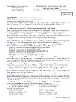
Fig. 1.2. Structural elements of a container (general purpose)
1 – corner fitting, 2 – corner post, 3 – end wall, 4 – end door, 5 – rear header, 6 – rear sill, 7 – side
wall, 8 – side door, 9 – side rib, 10 – bottom, 11 – cross member, 12 – floor, 13 – roof, 14 – top side
rail, 15 – bottom side rail, 16 – fork lift pockets (internal – for an empty container), 17 – locking
device, 18 – gooseneck tunnel.
Type of container – the container design type which complies with the
requirements of the present Rules and has been approved for manufacture.
1.3
1.3.1
.1
.2
.3
.4
.5
.6
Scope of Survey
PRS’ construction survey of containers covers the following:
consideration and approval of technical documentation;
construction survey;
testing;
marking and stamping;
issue of certificates;
approval of the manufacturer’s works and testing stations.
1.3.2 The survey is carried out according to the provisions of the present Rules,
with due regard paid to the applicable requirements of PRS’ General Survey
Regulations.
10
1.4
Technical Documentation
1.4.1 Prior to manufacture of a single container or a prototype of container
design type, technical documentation, in triplicate, is to be submitted to PRS for
approval. The documentation is to contain the following:
.1 specification of the container, including a description of its construction,
dimensions, full details of the materials used, workmanship, welding
procedure, assembly procedure, finishing and painting;
.2 assembly drawings, sections drawings of joints and connections of
individual elements, indicating the material used;
.3 test programme, indicating the internal and external loadings and the
methods of their application, should the loadings applied differ from those
generally assumed.
1.4.2 If necessary, PRS may require to be supplied with additional drawings and
specifications.
2
2.1
PRINCIPLES FOR APPROVAL OF CONTAINERS,
MANUFACTURER’S WORKS AND TESTING STATIONS
Approval of Containers
2.1.1 Approval of container by PRS means that the container design type or
a single container meets the requirements of the present Rules, is safe in handling
and capable of carrying cargoes in accordance with its designation.
2.1.2 To obtain approval of container design type or a single container,
application is to be submitted to PRS.
2.1.3 The application for approval of container design type or a single container
is to be accompanied by technical documentation, specified in 1.4, to be approved
by PRS.
2.1.4 A prototype (a sample unit of the container design type or a single
container) is to be subjected to tests in accordance with the requirements of these
Rules in the presence of PRS’ Surveyor.
2.1.5 On satisfactory completion of container prototype tests, PRS issues Type
Approval Certificate for container design type, hereinafter referred to as Approval
Certificate.
2.1.6 Approval Certificate entitles the manufacturer to affix the CSC Safety
Approval Plate to each container of the series built in accordance with an approved
design type and to a single container (CSC – International Convention for Safe
Containers, 1972, with amendments and supplements).
11
2.1.7 Containers which are modifications of the approved design type may be
accepted by PRS for service without any additional tests if so considered having
regard to the nature of modifications made.
2.2
2.2.1
Approval of Series Containers Manufacturers and Testing Stations
Approval of Series Containers Manufacturers
2.2.1.1 Prior to manufacture of series containers, the manufacturer is to establish
an effective quality control system approved by PRS. The quality control
documentation of series produced containers, in triplicate, is to be submitted to
PRS for approval and is to contain:
.1 a description of the works’ organization;
.2 the Quality Manual (if the works has established the Quality Management
System);
.3 scope of responsibility of the quality control department and confirmation
of its independence from production departments;
.4 the system used for introducing changes, approved by PRS, to technical
documentation, technical specification and manufacture process, as well as
arrangements to ensure their implementation at appropriate stages of
containers manufacture;
.5 arrangements made to ensure that the supplied materials and services meet
the design requirements approved by PRS;
.6 arrangements made by the works’ quality control to verify the measurements
of the instruments frequently used for determining the principal dimensions
of containers and their components;
.7 materials and container components storage conditions;
.8 the system of identification and rejection of defective container
components;
.9 approved procedures for container prefabrication and assembly;
.10 qualifications of personnel engaged in container prefabrication and
assembly;
.11 internal audits and corrective actions system;
.12 the system of documenting particular stages of container manufacture;
.13 specimens of documents for each container to be completed during its
production, as well as during carrying out recommendations and changes.
2.2.1.2 The manufacturer of series containers is obliged to:
.1 submit, at PRS’ request, any container of the approved design type for
external examination;
.2 affix the CSC Safety Approval Plate to each series container made in
conformity with the approved design type, indicating all required data, as
well as to affix the PRS emblem to each built container;
12
.3
.4
.5
.6
.7
agree with PRS any changes in container structure, technical specification
or container manufacture process;
in cases mentioned in 2.2.1.2.3 – to affix the CSC Safety Approval Plate
after approval, by PRS, of all these changes;
keep a record of containers manufactured to the approved design type,
showing at least the identification number of each container established by
the manufacturer, production date, the name and address of the Owner to
whom the container is to be delivered, as well as register of documents of
tests and checking;
advise PRS, in due time, about the date of beginning the manufacture of
each new series of containers made in conformity with the approved design
type;
re-approve technical documentation of containers at intervals specified in
General Survey Regulations.
2.2.1.3 Inspection of the manufacturer’ works is carried out by PRS to verify the
data provided in the works approval documentation.
2.2.1.4 If the results of the inspection are satisfactory, Approval Certificate will
be issued by PRS to the works. The Approval Certificate will be valid for 4 years.
2.2.2
Approval of Testing Stations
2.2.2.1 Container testing station is to be approved by PRS. To obtain approval,
application is to be submitted to PRS.
The application is to be accompanied by documentation, in triplicate,
containing:
.1 a general description of the testing station;
.2 a description of the testing station equipment allowing to perform all
required tests;
.3 information on owned measuring instruments which should be provided
with appropriate seals and/or valid verification certificates issued by
competent bodies;
.4 kinds and types of containers which may be subjected to testing;
.5 information on the duration of each test.
2.2.2.2 PRS carries out inspection of the testing station and participates in the
tests of containers, making itself sure as to the possibility of carrying out the tests
according to the prototype tests programme.
2.2.2.3 If the results of the inspection and the tests, specified in 2.2.2.2, are
satisfactory, Approval Certificate will be issued by PRS to the testing station.
13
2.2.2.4 Testing station is to keep copies of test reports and records of all tested
containers, showing at least: kind and type of container, names and addresses of the
Owners, container identification number, types and dates of the performed tests.
2.3
Survey of Series Containers Manufacture
2.3.1 Containers manufactured in series may be surveyed as single containers
directly by PRS or by the works’ quality control with subsequent PRS’ survey of
containers submitted in batches.
2.3.2 The condition for survey of containers by the works’ quality control is
Approval Certificate issued to the works by PRS in accordance with 2.2.1.
2.3.3 As a result of the survey, containers are issued with Individual Freight
Container Certificate, Tank Container Certificate or Freight Containers
Production Certificate.
2.3.4 Tank containers manufactured on a single or series basis are subject to
PRS’ direct survey.
2.3.5
Tests of Containers Manufactured in Series
2.3.5.1 Containers manufactured in series are to be subjected to the following
tests and checks:
.1 external examination – each container;
.2 checking the container dimensions – each container;
.3 weathertightness test – each container;
.4 lifting from the top corner fittings – every 50th container;
.5 transverse racking test – every 50th container;
.6 floor strength test – every 100th container;
.7 refrigerating plant operation test – each container;
.8 capacity test of refrigerating plant – every 250th container;
.9 hydraulic test and tightness test of the tank in tank container – each tank
container.
2.3.5.2 The results of the tests and checks of series containers are to be
documented and maintained by the works in accordance with 2.2.1.
3
3.1
GENERAL TECHNICAL REQUIREMENTS
Dimensions and Mass
3.1.1 Depending on dimensions and mass, the following types of containers are
distinguished: 1 EEE, 1EE, 1AAA, 1AA, 1A, 1AX, 1BBB, 1BB, 1B, 1BX, 1CC,
1C, 1CX, 1D and 1DX.
14
3.1.2 Nominal dimensions and tolerances of containers, detailed in 3.1.1, as well
as their maximum gross weight are shown in Table 3.1.2. For such containers, the
change of their height and increase of the maximum gross mass is permitted. The
dimensions and weight of other types of containers are subject to special
consideration of PRS.
3.1.3 Dimensions and tolerances given in Table 3.1.3 are to comply with the
measurements taken at a temperature of +20 °C (293 K).
15
Table 3.1.2
Container characteristics
Type of container
1EEE
1EE
1AAA
Height
0
0
0
2896 −5
2896 −5 2591 −5
H
External
Width
0
0
0
dimensions
2438 −5
2438 −5 2438 −5
W
[mm]
Length
0
0
0
13716 −10 13716 −10 12192 −10
L
Maximum gross
30480 30480 30480
weight R, [kg]
Distance
between
the centers
of
apertures
of the
corner
fittings,
[mm]
1AA
1A
1AX
1BBB
1BB
1B
1BX
2591 −5 2438 −5 <2438 − 5
0
0
2896 −5
2591 −5
0
0
0
2438 −5 2438 −5 2438
−5
0
2438 −5
2438 − 5
0
0
0
12192 −1012192 −1012192
−10
9125 −10
9125 −10
9125 −10
9125 −10
30480
30480
30480
30480
0
30480
0
30480
30480
0
0
0
0
0
2438 −5
0
2438 −5
0
0
1CC
1CX
1D
1DX
0
0
2438 −5
0
<2438 −5
0
2438 −5
<2438 −5
0
0
2438 −5
0
2438 −5
0
2438 −5
2438 −5
6058 −6
0
0
6058 −6
0
6058 −6
0
2991 −5
2991 −5
30480
30480
30480
10160
10160
<2438 −5
2591 −5
0
2438 −5
2438 −5
0
1C
0
0
0
S
11985
11985
11985
11985
11985
11985
8918
8918
8918
8918
5853
5853
5853
2787
2787
P
2259
2259
2259
2259
2259
2259
2259
2259
2259
2259
2259
2259
2259
2259
2259
K1 max,
[mm]
19
19
19
19
19
19
16
16
16
16
13
13
13
10
10
K2 max,
[mm]
10
10
10
10
10
10
10
10
10
10
10
10
10
10
10
16
3.2
Corner Fittings
3.2.1
General Requirements
3.2.1.1 All containers are to be equipped with top and bottom corner fittings.
1EEE and 1EE containers are to also have intermediate corner fittings in the
1AAA/1AA/1A position.
Dimensions and tolerances of corner fittings, as well as their mutual
arrangement are shown in Figs. 3.2.1.1-1, 3.2.1.1-2, 3.2.1.1-3 and Table 3.1.2.
Each top corner fitting is to consist at least of top, side and face walls. Each
bottom corner fitting is to consist at least of bottom, side and face walls.
end wall
front wall
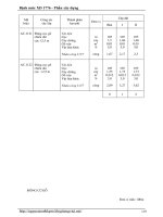
Fig. 3.2.1.1-1.
Mutual arrangement of corner fittings
L – external length of the container; W – external width of the container; H – maximum height of the
container; S – distance between the centres of apertures in corner fittings on the length of the
container; P – distance between the centres of apertures in corner fittings on the breadth of the
container; D – diagonals of the container measured between the centres of apertures in corner fittings:
D1, D2, D3, D4, D5, D6;
K1 – difference between D1 and D2 or D3 and D4 (i.e. K1 = D1 − D2 or D3 −D4);
K2 – difference between D5 and D6 (i.e. K2 = D5 − D6).
Letters in circles are given to facilitate completion of the documents.
17
Fig. 3.2.1.1-2.
Top corner fitting
The external and internal rounding radii, not shown in the figure, are not to be greater than 3 mm.
18
Fig. 3.2.1.1-3. Bottom corner fitting
The external and internal rounding radii, not shown in the figure, are not to be greater than 3 mm.
3.2.1.2 In the constructed container, the external upper surfaces of the top corner
fittings are to protrude at least 6 mm above the highest point of the roof.
Where corner gussets are provided in the vicinity of the top corner fittings, they
are to be of such thickness as not to protrude above the upper faces of the top
corner fittings. The gussets may extend over the whole width of the container, but
they cannot extend more than 750 mm from either end of the container.
19
3.2.1.3 The bottom corner fitting is to withstand the load equal to 150 kN applied
perpendicular to an area of 25 x 6 mm being the lower surface of the corner fitting
– see Fig. 3.2.1.3.
Fig. 3.2.1.3. Bottom corner fitting (bottom view)
3.2.1.4 Corner fittings are to be capable of transmitting the following loads:
.1 stacking:
– top corner fittings – 848 kN, when the test corner fitting or a pad is
offset by 25.4 mm laterally and by 38 mm longitudinally;
– bottom corner fittings – 954 kN for the whole bottom area of the
fitting;
– bottom corner fittings – 848 kN, when the test corner fitting or
a pad is offset by 25.4 mm laterally and by 38 mm longitudinally;
.2 lifting:
– top corner fittings – 150 kN (with a twistlock, hook or shackle);
– bottom corner fittings – 300 kN (at an angle of 30o with respect to
the horizontal);
.3 longitudinal restraint:
– bottom corner fittings – 300 kN on each corner fitting;
.4 fastening of container by fittings:
– apertures in the face and side walls of the bottom and top corner fittings
– 300 kN perpendicularly and 150 kN horizontally for each corner
fitting;
– the lines of action of the forces are to be positioned at a distance not
greater than 38 m from the relevant surface of the fitting;
– the maximum resultant force due to the action of the horizontal and
perpendicular force components is not to exceed the values given in
Fig. 3.2.1.4.
20
Horizontal force
component
Boundary of zone
of limitation
Vertical force
component
Fig. 3.2.1.4.
3.2.2
Diagram of loads of corner fittings of the container when secured
Corner Fittings Marking
The below symbols (at least 10 mm high) are to be durably cast in, moulded or
embossed at the inner surface of each fitting:
.1 the manufacturer’s brand;
.2 heat number (or batch number) – abbreviated symbol allowing to retrace
the cast;
.3 PRS’ stamp.
3.2.3
Certificates
For each fitting or a batch of fittings subject to PRS’ survey or quality control,
a certificate is to be issued, containing at least the following data:
.1 purchaser’s name and order number,
.2 type of corner casting and cast steel grade,
.3 assembly drawing number,
.4 method of manufacture,
.5 heat or batch number,
.6 chemical composition of the material,
.7 details of heat treatment,
.8 number of corner fittings and their total weight,
.9 results of inspections and mechanical tests.
3.3
Base Structure
3.3.1 In containers subjected to static and/or dynamic tests with the load
distributed uniformly by a gravity force equivalent to a mass of 1.8 R, no part of
the base structure is to protrude by more than 6 mm below the lower surface of the
bottom corner fittings.
21
3.3.2 The base structure of type 1AAA, 1AA, 1A, 1AX, 1BBB, 1 BB, 1B, 1BX,
1CC, 1C and 1CX containers is to be such that the load is transferred from the base
to the body of the means of transport.
3.3.3 The distance between the lower surfaces of rear/front sills and
crossmembers of the base structure and the plane passing through the lower
surfaces of the bottom corner fittings is to be 12.5 +−15.5 mm.
If sills, in the vicinity of the bottom corner fittings, are fitted with bottom corner
gussets, they are to be of such thickness as to ensure at least 5 mm distance
between the lower faces of the bottom corner fittings and the lower faces of the
gussets. Such gussets are not to extend more than 550 mm from the outer end and
not more than 470 mm from the side faces of the bottom corner fittings.
3.3.4 The minimum number of pairs of the load transfer areas, for a given type of
container, is to be as follows:
.1 1AAA, 1AA, 1A and 1AX containers – 5;
.2 1AAA, 1AA, 1A and 1AX containers (without continuous gooseneck
tunnel) – 6;
.3 1BBB, 1BB, 1B and 1 BX containers – 5;
.4 1CC, 1C and 1CX containers – 4.
The load transfer zones are to be at least 375 mm in width, as shown in Figs.
3.3.4-1 and 3.3.4-2.
3.3.5 Each pair of areas in the load transfer zones in the cross-bars of the face
and door frame base is to be capable of transferring the gravity force of 0.5 R.
Every other intermediate pair of areas in the load transfer zones is to transfer the
gravity force of 1.5 R/n, where n – number of intermediate pairs of areas in the load
transfer zones.
Each load transfer area is to be at least 25 mm in length.
Each load transfer area of gooseneck tunnel (see Fig. 3.3.4-2) consists of two
parts – the upper part A and the bottom part B – which constitute a common load
transfer area. The total area of A and B areas is not to be less than 1250 mm2.
Load transfer areas
Load transfer zones
Fig. 3.3.4-1.
Diagram of distribution of the load transfer zones from the container base to the body
(Dimensions in mm)
22
Fig. 3.3.4-2.
Distribution of the load transfer areas in gooseneck tunnel (where the areas are not continuous)
3.3.6 The distance between the load transfer areas on the base cross-bars and the
nearest pair of load transfer areas is to be:
.1 from 1700 to 2000 mm – for containers having the minimum number of
pairs of load transfer areas;
.2 from 1000 to 2000 mm – for containers having at least one pair of the load
transfer areas more than the required minimum.
Distribution of the load transfer areas is given in Figs. 3.3.6-1, 3.3.6-2, 3.3.6-3
and 3.3.6-4.
Fig. 3.3.6-1.
Distribution of the load transfer areas in 1AA, 1A and 1AX containers
(without gooseneck tunnel)
23
Fig. 3.3.6-2.
Distribution of the load transfer areas in 1AAA, 1AA, 1A and 1AX containers
(with gooseneck tunnel)
Fig. 3.3.6-3.
Distribution of the load transfer areas in 1BBB, 1BB, 1B and 1BX containers
24