2 3 casing cementing
Bạn đang xem bản rút gọn của tài liệu. Xem và tải ngay bản đầy đủ của tài liệu tại đây (2.36 MB, 89 trang )
Network of Excellence in Training
Cementing Technology
© COPYRIGHT 2001, NExT.
All Rights Reserved
Cementing Technology
• Lecture Contents:
– Lecture Objectives,
– Primary Cementing
– Cement Classification,
– Cement Additives,
– Casing Hardware,
– Cement Evaluation
– Remedial Cementing Techniques
• Cement Plug
• Squeeze Cementing.
2
© COPYRIGHT 2001,
.
All Rights Reserved
Cementing Technology
• Lecture Objectives:
At the end of this course, YOU will be able to:
• Understand the difference between primary and secondary
cementing,
• Identify classes of cement appropriate for different depth
range,
• Explain how the properties of cement may be altered by
the use of additives,
• Identify basic casing hardware and describe ways to assist
in the preparation of a cement job,
• Describe cement bond evaluation techniques
• Describe the remedial cementing techniques and calculate
the balanced plug,
3
© COPYRIGHT 2001,
.
All Rights Reserved
Primary Cementing
• Introduction;
– Primary cementing is the introduction of cementacious
material into the annulus between casing and openhole to:
• Provide zonal isolation,
• Support axial load of casing string and other strings to be
run later,
• Provide casing protection,
• Support the borehole,
– Secondary/or Remedial jobs:
• Squeeze cementing,
• Cement plug.
4
© COPYRIGHT 2001,
.
All Rights Reserved
Primary Cementing
• Conductor Pipe:
• Cementing Procedure:
– Plugs not used,
– Large excess required,
– Thru-drill pipe cementing common,
– BOP’s not usually connected,
– Common Cements; Accelerated Neat.
5
© COPYRIGHT 2001,
.
All Rights Reserved
Primary Cementing
• Thru-Drill Pipe Cementing;
• Key Points:
– Cement Contamination,
– Channeling,
– Displacement,
– Pump Until Slurry is at
surface.
6
© COPYRIGHT 2001,
.
All Rights Reserved
Primary Cementing
• Outside Cementing;
• Purpose:
– Bring Cement to Surface.
• Macaroni TBG used:
– Max depth 250 - 300 ft,
– High friction Pressures,
– Non-standard Connections.
7
© COPYRIGHT 2001,
.
All Rights Reserved
Primary Cementing
• Surface Casing:
• Cementing Procedure:
– Excess of 100%,
– Recommended thru-drillpipe method to save:
» Cement,
» Rig time.
– Common Cements:
» Lead light slurry with high yields,
» Neat tail slurries with good compressive strength,
» Reduce WOC to a minimum with accelerators.
8
© COPYRIGHT 2001,
.
All Rights Reserved
Primary Cementing
• Intermediate Casing (also called Protection);
• Cementing Procedure:
– Cemented to surface or to previous casing shoe,
– Two stage jobs common,
– Plugs, casing equipment and casing accessories are usual,
– Good cementing practices are required,
– Large cement volumes.
• Common Cements:
– Typically filler slurries followed by high compressive tail,
– Specialized (light, heavy, salt - saturated, etc.).
9
© COPYRIGHT 2001,
.
All Rights Reserved
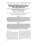
SECOND STAGE
Primary Cementing
• Two Stage Cementing;
• Key Points:
– Separation and isolation of
zones,
STAGE COLLAR
– Reduced hydrostatic,
– Can leave zone in the annulus
uncemented (cement at TD
and surface),
FIRST STAGE
– Loss zone.
FLOAT COLLAR
FLOAT SHOE
10
© COPYRIGHT 2001,
.
All Rights Reserved
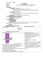
Primary Cementing
• Liners;
Drill pipe
Wiper Plug
– Key points:
• Liner-lap integrity,
• Separation and isolation of zones,
• Small volumes.
• Critical cement job.
Liner
Hanger
Running
Tool
Shear
Pin
Liner
Wiper
Plug
11
© COPYRIGHT 2001,
.
All Rights Reserved
Cement Classification
• API has identified classes for neat Portland cement.
• The criteria used by API is based on the degree of
the fineness of the cement particles.
• Class A:
– Intended for use from surface to 6000 ft, when
special properties are not required.
• Class B:
– Intended for use from surface to 6000 ft, when
condition require moderate to high sulfate
resistance.
12
© COPYRIGHT 2001,
.
All Rights Reserved
Cement Classification
• Class C:
– Intended for use from surface to 6000 ft, when
conditions require high early strength.
• Class D:
– Intended for use from 6000 to 10000 ft, under
conditions of moderately high temperatures and
pressures.
• Class E:
– Intended for use from 10000 to 14000 ft, under
conditions of high temperatures and pressures.
13
© COPYRIGHT 2001,
.
All Rights Reserved
Cement Classification
• Class F:
– Intended for use from 10000 to 14000 ft, under
conditions of extremely high temperatures and
pressures.
• Class G:
– Intended for use from surface to 8000 ft, it can be
used with retarders and accelerators to cover a
wide range of well depths and temperature.
• Class Geotherm:
– This is not an API, but it is basically a class G with
silica flour. In order to withstand; high temperature,
pressure wells.
14
© COPYRIGHT 2001,
.
All Rights Reserved
Cement Classification
• Class H:
– Intended for use from surface to 8000 ft, can be
accelerated or retarded to cover a wide range of well
depths and temperature.
• Class J:
– Intended for use as manufactured from 12000 to
16000 ft and can be accelerated or retarded.
15
© COPYRIGHT 2001,
.
All Rights Reserved
Cement Properties
• The properties vary according to the objectives
of the cement job. Thus for casing job the
cement must:
– Yield a slurry of given density while still exhibiting
desired slurry properties,
– Be easily mixed and pumped,
– Meet optimum rheological properties required for mud
removal,
– Maintain both physical and chemical characteristics
during placement,
– Be impermeable to annular gas, if present while setting.
16
© COPYRIGHT 2001,
.
All Rights Reserved
Cement Properties
• After Placement;
– Develop strength quickly,
– Develop sufficient strength in the long term,
– Develop casing and formation bond strength,
– Have as low permeability as possible,
– Maintain quality even under severe temperature and
pressure.
17
© COPYRIGHT 2001,
.
All Rights Reserved
Cement Properties
• The properties that are measured to determine a
particular job design are categorized as:
– Cement Slurry Properties,
– Set Cement Properties.
• The properties of the cement will vary from one
well to another and will be determined by the
characteristics of the well.
18
© COPYRIGHT 2001,
.
All Rights Reserved
Cement Properties
• Cement Slurry Properties;
– Water Cement Ratio:
• Define the minimum and maximum boundaries of water
content in slurry,
– The minimum being the water necessary to maintain the
cement pumpable,
– The specific definition being 100 BC (Bearden Unit)
consistency,
– The maximum being the water limit beyond which particles
will not remain in suspension until the cement has set. The
specification being 3.5 ml of free water after the cement has
stood for 2 hours,
• Exceeding the maximum ratio will cause pockets of free
water to form and reduce the strength of set cement.
19
© COPYRIGHT 2001,
.
All Rights Reserved
Cement Properties
• Cement Slurry Properties;
– Slurry Density:
• Measured in PPG or Kg/l, and is governed by the maximum and
minimum water cement ratio,
• Specific well conditions may require the use of lighter or heavier
cements,
• Lower density slurries may be obtained by using lightning materials such
as Pozzolans etc,
• Higher density slurries may be obtained by using water content below the
minimum acceptable. In such cases pumpability is achieved by using
dispersants to increase fluidity.
20
© COPYRIGHT 2001,
.
All Rights Reserved
Cement Properties
• Cement Slurry Properties;
– Fluid Loss Control:
• Variation in water content will affect many characteristics such as
thickening time, rheology and compressive strength,
• Thus a neat slurry placed over a permeable formation will lose filtrate
resulting in dehydration of the slurry and decrease in the pumpability,
• Flash setting may occur due to rapid dehydration,
• Loss circulation may occur due to an increase in friction pressure,
• Final compressive strength maybe reduced due to lack of hydration.
21
© COPYRIGHT 2001,
.
All Rights Reserved
Cement Properties
• Cement Slurry Properties;
– Fluid Loss Control:
• Some typical fluid loss values are:
– For normal uncontrolled neat cement; 800/1000 ml/ 1000 psi
for 30 min,
– For cementing casing; 100/200 ml/ 1000 psi for 30 min,
– For cementing liners; 50/100 ml/ 1000 psi for 30 min,
22
© COPYRIGHT 2001,
.
All Rights Reserved
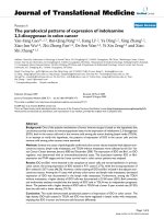
Cement Properties
• Cement Slurry Properties;
– Fluid Loss Control:
• Flash setting due to dehydration followed by fracturing of
lower zone due to increased frictional losses;
Hydrostatic Pressure
Filtrate
Filtrate
Dehydrated Cement
Weak Zone
Fractured Weak Zone
23
© COPYRIGHT 2001,
.
All Rights Reserved
Cement Properties
• Cement Slurry Properties;
– Slurry Rheology:
• The rheological parameters govern the slurries ability to
flow with respect to:
– Pressure loss characteristics,
– Flow through small opening and vugs,
– Mud removal capability.
24
© COPYRIGHT 2001,
.
All Rights Reserved
Cement Properties
• Cement Slurry Properties;
– Slurry Rheology:
• Studies have shown that properties that exhibit flat profiles
tend to maintain separation of different fluids,
• Turbulent and plug flow traditionally are preferred over
laminar flow.
Velocity Profiles
Plug
Laminar
Turbulent
25
© COPYRIGHT 2001,
.
All Rights Reserved