5 1 dir drilling and surveying
Bạn đang xem bản rút gọn của tài liệu. Xem và tải ngay bản đầy đủ của tài liệu tại đây (1.95 MB, 63 trang )
Network of Excellence in Training
Introduction to
Directional Drilling
© COPYRIGHT 2001, NExT.
All Rights Reserved
Introduction to Directional
Drilling
• Lecture Contents
– Lecture Objectives,
– Definition,
– Well Types,
– Terminology,
– Applications,
– Basic Survey Calculation Methods,
– Directional Drilling Tools.
2
© COPYRIGHT 2001,
.
All Rights Reserved
Introduction to Directional
Drilling
• Lecture Objectives
At the end of this lecture YOU will be able to:
– Define directional drilling techniques
– Identify well types,
– Describe the related terminologies,
– Understand the applications of directional drilling,
– List surveying and calculation methods,
– Describe Various BHAs and Downhole Tools.
3
© COPYRIGHT 2001,
.
All Rights Reserved
Introduction to Directional
Drilling
• Definition
– Directional Drilling is the practice of deviating a well
bore along a planned course to a subsurface target whose
location is a given lateral distance and direction from the
vertical.
4
© COPYRIGHT 2001,
.
All Rights Reserved
Introduction to Directional
Drilling
• Historical Background
- the late 1920’s
1st application of oil well surveying using the acid
bottle inclinometer
- 1929
Directional inclinometer with magnetic needle.
- the 1930’s
1st controlled directional well drilled
(initially for unethical proposes, to cross property lines)
- 1934
Controlled DD was used to kill a wild well.
Beginning of controlled DD
5
© COPYRIGHT 2001,
.
All Rights Reserved
Introduction to Directional
Drilling
• Significant Events
< 1950 Magnetic Single Shot
(survey after drilling)
1970’s Steering Tool
1960’s Mud Motor
(versatile kick off tool)
(survey while drilling)
1980 MWD
(mud pulse telemetry - no wireline)
1980’s LWD
1980’s Steerable Motor
(log quality Data)
1988 Horizontal
Drilling
1990’s GeoSteering
(drilling for drainage)
(geologic vs geometric steering)
1999 Steerable Rotary
Drilling
200? Better Measurements/Data Rates, Multi-Laterals?……….?
6
© COPYRIGHT 2001,
.
All Rights Reserved
Introduction to Directional
Drilling
• Well Types
Vertical Type
“S” Type
Slant (J) Type
Horizontal Type
7
© COPYRIGHT 2001,
.
All Rights Reserved
Introduction to Directional
Drilling
• Applications
Sidetracking
Salt Dome Drilling
Inaccessible Locations
Fault Controlling
8
© COPYRIGHT 2001,
.
All Rights Reserved
Introduction to Directional
Drilling
• Applications
Multiple Exploration
Relief well
Multilateral Offshore
Short, Medium, & Long Radius
9
© COPYRIGHT 2001,
.
All Rights Reserved
Introduction to Directional
Drilling
• Terminology
UP
MN
Azimuth Angle
W
E
Horizontal Projection of
Borehole
S
Inclination Angle
DOWN
BOREHOLE
10
© COPYRIGHT 2001,
.
All Rights Reserved
Introduction to Directional
Drilling
• Terminology
Dir
N
0
AZ
KOP
Inc
EOB
TVD
MD
HD
11
© COPYRIGHT 2001,
.
All Rights Reserved
Introduction to Directional
Drilling
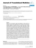
• Terminology;
– TVD; Vertical distance to a position on the well trajectory,
– MD; Distance to a position on the well trajectory
measured along the hole (AHD),
– KOP; Kick-off Point
– EOB; End of Build Up Section,
– Dir; Angle measured from the north,
– HD; Horizontal displacement to target.
12
© COPYRIGHT 2001,
.
All Rights Reserved
Network of Excellence in Training
Surveying
© COPYRIGHT 2001, NExT.
All Rights Reserved
Introduction to Directional
Drilling
• Wellbore Survey
– Background
• Recently, technology have advanced in such away that the
former directional drilling tools were replaced with an
advanced ones such as:
– Steerable mud motors,
– MWD,
– Andergauge Stabilizers,
– LWD.
• These tools, in combination, could provide a 3D well profiles
without changing BHA and have enabled the drilling of
horizontal and multi lateral wells.
14
© COPYRIGHT 2001,
.
All Rights Reserved
Introduction to Directional
Drilling
• Wellbore Survey
– Why are Surveys Required?
• Satisfy local regulatory agencies,
• Stay within lease boundaries,
• Construct accurate subsurface maps,
• Determine wellbore shape,
• Reach a target by steering.
15
© COPYRIGHT 2001,
.
All Rights Reserved
Introduction to Directional
Drilling
• Wellbore Surveys
– Basic Measurements
• Inclination
– Angle between the borehole and vertical.
• Azimuth
– Angle between north and the horizontal projection of
the borehole.
• Distance
– Course length between survey stations, measured by
length of pipe added at the surface.
16
© COPYRIGHT 2001,
.
All Rights Reserved
Introduction to Directional
Drilling
• Wellbore Surveys
– Type of Tools
• Single Shots,
• Multishots,
• Gyro,
• MWD.
17
© COPYRIGHT 2001,
.
All Rights Reserved
Introduction to Directional
Drilling
• Wellbore Surveys
• Single Shot Survey
– Simple Design
• Compass Card
Aligns with North,
• Pendulum Assembly
Displays Inclination,
• Camera Captures
the image on Film,
• Timer Turns-on the
Light.
– Inexpensive and
Dependable
– Time Consuming
– Temperature Sensitive
Battery Housing
Timer / Sensor
Camera Housing
Compass Unit
18
© COPYRIGHT 2001,
.
All Rights Reserved
Introduction to Directional
Drilling
• Wellbore Surveys
– Gyro Survey Tool
• Balanced spinning mass,
• Free to rotate on one or more axis,
• Is resistant to external forces ,
• Gyro is accurately aligned to reference before use,
• Maintains this heading throughout survey interval,
• No interference due to magnetism,
• Is used when compass heading not dependable,
• Corrections for change in heading can be applied later.
19
© COPYRIGHT 2001,
.
All Rights Reserved
Introduction to Directional
Drilling
• Wellbore Surveys
– Gyro Survey Tool
20
© COPYRIGHT 2001,
.
All Rights Reserved
Introduction to Directional
Drilling
• Wellbore Surveys
– Multi-Shot Survey Tools
• Magnetic Multishot
– Similar to singleshot,
– Taken at timed intervals,
– Survey record is stored on film.
• Gyro Multishot
– Surveys taken in magnetic environment,
– Survey record is stored on film.
• Electronic Multishot
– Requires non-magnetic environment,
– Tool memory is dumped at the surface.
21
© COPYRIGHT 2001,
.
All Rights Reserved
Introduction to Directional
Drilling
• Wellbore Surveys
– MWD Tool
• Tool Functionality
– MWD system measure downhole information and transmit
data back to surface without interrupting normal drilling
operations,
– Downhole sensors are located in the MWD which made-up
inside a non magnetic DC,
– Data from the sensor is transmitted through the mud
column in the drillstring and the signal is decoded at the
surface,
– This procedure is known as mud pulse telemetry,
– The whole procedure does not require wireline operations.
22
© COPYRIGHT 2001,
.
All Rights Reserved
Introduction to Directional
Drilling
• Wellbore Surveys
– MWD Tool
• Surface System
23
© COPYRIGHT 2001,
.
All Rights Reserved
Introduction to Directional
Drilling
• Wellbore Surveys
– MWD Tool
• Graphic Presentation
24
© COPYRIGHT 2001,
.
All Rights Reserved
Introduction to Directional
Drilling
• Magnetic Declination Angle
MAGNETIC
NORTH
LAT 75.5N
LONG 100.5W
TRUE NORTH
X
X
25
© COPYRIGHT 2001,
.
All Rights Reserved