Honeywell black CALNVR manual
Bạn đang xem bản rút gọn của tài liệu. Xem và tải ngay bản đầy đủ của tài liệu tại đây (2.97 MB, 128 trang )
NVR
User's manual
CAUTION:
Do not place heavy objects on the device;
Do not let any solid or liquid to penetrate inside the device;
Please regularly with a brush on the circuit board, connectors, chassis fans, chassis etc. dusting, cleaning work
before making body, turn off the power and unplug the power;
Do not attempt to disassemble this equipment, repair, or replacement parts.
Use of the environment:
Do not install this equipment in a wet environment;
Do not expose this apparatus in smoky, dusty environments;
Avoid strong collision; do not drop the machine;
Please keep this product installed horizontally mounted in a stable place, pay attention to prevent falling
product;
Install in a well ventilated place, Do not block the vents of the product;
Can only be used within the rated of input and output range.
2
I.
II.
3
NVR Product Manual ......................................................................................................................................................... 5
1. Introduction ............................................................................................................................................................... 5
1.1
Product Description ....................................................................................................................................... 5
1.2
Main Functions .............................................................................................................................................. 5
2. Unpacking and cable connection ............................................................................................................................... 6
2.1
Unpacking ...................................................................................................................................................... 6
2.2
Hard disk installation ..................................................................................................................................... 6
2.3
Shelf Installation ............................................................................................................................................ 7
2.4
Audio and video input and output connections ............................................................................................ 7
2.5
Alarm input and output connections............................................................................................................. 8
2.6
Connect to Dome camera ............................................................................................................................ 10
3. Product Operation ................................................................................................................................................... 10
3.1
Turn on ......................................................................................................................................................... 10
3.2
Turn off ........................................................................................................................................................ 11
3.3
System Login ................................................................................................................................................ 11
3.4
Preview ........................................................................................................................................................ 12
3.5
Desktop shortcut menu ............................................................................................................................... 12
4. Main Menu .............................................................................................................................................................. 22
4.3
Alarm function ............................................................................................................................................. 26
4.4
system settings ............................................................................................................................................ 30
4.5
Manage Tools ............................................................................................................................................... 44
4.6
System Info .................................................................................................................................................. 51
4.7
Shut down system........................................................................................................................................ 53
5. FAQ and maintenance ............................................................................................................................................. 54
5.1
FAQ .............................................................................................................................................................. 54
5.2
Maintenance ................................................................................................................................................ 58
CAL-CMS200 manual ....................................................................................................................................................... 59
1. Software Instruction ................................................................................................................................................ 59
1.1
Summary...................................................................................................................................................... 59
1.2
Features ....................................................................................................................................................... 59
2. Installation Instruction ............................................................................................................................................ 60
2.1
Running Environment .................................................................................................................................. 60
2.2
Installation Steps ......................................................................................................................................... 61
3. Introduction of Basic Functions ............................................................................................................................... 63
3.1
CAL-CMS200 Operation Main Menu ........................................................................................................... 63
4. Monitor .................................................................................................................................................................... 66
4.1
Preview ........................................................................................................................................................ 66
4.2
Right-click Menu .......................................................................................................................................... 66
4.3
PTZ Control .................................................................................................................................................. 67
4.4
Color ............................................................................................................................................................ 68
5. System settings ........................................................................................................................................................ 68
5.1
Monitoring points manager ......................................................................................................................... 68
5.2
Local Config.................................................................................................................................................. 72
5.3
Device Config. .............................................................................................................................................. 77
5.4
User .............................................................................................................................................................. 89
5.5
Local Log ...................................................................................................................................................... 90
6. Record ...................................................................................................................................................................... 91
6.1
Playback ....................................................................................................................................................... 91
7. Advanced ................................................................................................................................................................. 96
7.1
Decoder ....................................................................................................................................................... 97
7.2
E-MAP ........................................................................................................................................................ 106
7.3
Tour ............................................................................................................................................................ 110
7.4
Task Config. ................................................................................................................................................ 111
II. CALNVRView Manual..................................................................................................................................................... 114
8. Introduction ........................................................................................................................................................... 114
9. Installation ............................................................................................................................................................. 114
10. Application Running............................................................................................................................................... 115
III.
Remote Cloud Operating Instructions ................................................................................................................... 123
Appendix Ⅰ
Appendix Ⅱ
Appendix Ⅲ
Remote controller operation ..................................................................................................................... 126
Mouse operation ....................................................................................................................................... 127
Hard disk capability calculation ................................................................................................................. 128
4
I. NVR Product Manual
1. Introduction
1.1 Product Description
The series NVR is designed especially for security and defense field which is an outstanding digital surveillance
product. It introduces embedded LINUX operating system which is more stable. It introduces standard H.264mp video
compressed format which insures the high quality image, low error coding ratio and single frame playing. It introduces
TCP/IP network technology which achieves the strong network communication ability and telecommunication ability.
The series NVR are widely used in power systems, telecommunications sector, banking security, industrial
enterprises, intelligent buildings, intelligent community, urban roads, airports, railway stations and other surveillance
applications.
1.2 Main Functions
Real-time surveillance
Spot interface、analog interface、VGA interface and HDMI interface,surveillance function through monitor or
display.
Storage
Non-working hard disk dormancy processing which is convenient to radiate heat, reduce power and extend the
life-span
Special storage format which insures the data safety
Compression
Real-time compression by individual hard disk which insures the audio and video signal stable synchronization
Backup
Through SATA interface and USB interface such as USB equipment, removable hard disk and so on
Through net download the files in the hard disk
Playback
Individual real-time video recording as well as searching, playback, network surveillance, recording check,
downloading and so on
Multi-playback mode
Zoom at arbitrary region
Net operating
Real-time monitoring can be carried out remotely via the network (including mobile phone)
Remote PTZ control
Remote video search and real-time playback
Alarm linkage
Alarm recording, round robin, the screen prompts, beep, mail, FTP
Communication interface
With RS485 interface, alarm input and PTZ control
With RS232 interface, scalable keyboard connection to the master, and connected to the computer serial port for
system maintenance and upgrades, and matrix control
With standard Ethernet interfaces, network remote access feature
5
Intelligent operating
Mouse action function
Fast copy and paste operating for the same setting
2. Unpacking and cable connection
2.1 Unpacking
When you receive the product:
First, check whether the packaging equipment has obvious damage. Selection of protective packaging materials
during transport can cope with most of the unexpected hit;
Then, remove the device, remove the plastic protective film NVR, check whether there is any visible damage to
the outside;
Finally, open the case, check the front panel data cable, power cable, power supply and motherboard fan
connector is loose.
Front panel and rear panel
Various interfaces on the front panel and the rear panel of the various key functions are described in detail in the
specification;
Please check carefully whether the product model on the front panel with foil products you ordered the same
model;
Label affixed to the rear panel, has a very important significance for our service work, please protect. In the
company's after-sales service when you contact us, you will need to provide the model and serial number to
order the label.
Check
In addition to checking for any obvious signs of damage, but please pay attention to check the front panel data
cable, power cable and the motherboard connection is loose.
2.2 Hard disk installation
When you use, first install the hard drive, the machine can install two hard drives inside (capacity no limit).
①disassemble the screw
④fix the screw of hard disk
②disassemble the cover
③fix the screw of hard disk
⑤connect the data wire
⑥connect the power wire
6
⑦cover the machine
⑧fix the cover
2.3 Shelf Installation
This product chassis specification is standard 1u, so it can be installed in the standard shelf.
Installation steps and attention items:
1、Keep the equipment have 15cm(6 inches)space around in order to air's circulation.
2、From bottom to shelf installation.
3、When multiple components install in the frame,please take preventive measures to avoid power socket
overload..
2.4 Audio and video input and output connections
2.4.1 Video input connections
No video input interface
Ensure a stable and reliable camera signal
Cameras should be installed in a suitable location, to avoid backlighting, low-light environment, or the use of
good results BLC camera, low-light cameras.
Camera and NVR power supply should be common ground, and reliable, in order to ensure the normal operation
of the camera.
2.4.2 Select and connect the video output device
Video output is divided into PAL / NTSCBNC (1.0VP-P, 75Ω) output and VGA output (VGA is optional)
Choose to use a computer monitor to replace the monitor should pay attention to the following questions:
1. Leave it on for too long, to extend the life of the equipment;
2. Regular degaussing, this will help maintain the normal operation of the display;
3. Away from strong electromagnetic interference devices.
Use TV as a video output device is an unreliable alternative. It also requires minimizing the use of time and
strictly controls the interference power caused by neighboring devices. Inferior TV leakage risks may cause damage to
other equipment.
2.4.3 Input audio signal
Audio is a BNC connector (only one to support intercom function).
Audio input impedance is high, and therefore must be used pickups active pickups.
Similar to the video input audio transmission requires line to avoid interference, avoid Weld, poor contact, and
special attention to prevent a string of high-voltage current into.
2.4.4 Audio Output
Audio output signal parameters NVR is generally greater than 200mv 1KΩ (BNC), you can directly connect the
low impedance headphones, powered speakers or other sound through power amplifier output devices. In the
case of external speakers and microphone spatial isolation can not be achieved, it is easy to produce output
howling phenomenon. At this point the measures to be taken are:
7
Directional better pickups;
Adjust speaker volume, making it lower than the threshold to produce howling;
Multi-use environment using sound-absorbing materials decoration, reduce reflection of the sound, improve the
acoustic environment;
Adjust the layout of pickups and speakers, but also can reduce the occurrence of howling situations.
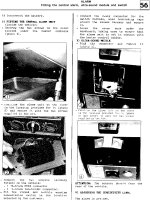
2.5 Alarm input and output connections
Before connecting the device, please note the following:
* Note: T Series devices without alarm input and output functions.
2.5.1 Alarm Input
Alarm input is grounding alarm input;
Alarm input requirements for ground voltage signal;
When the alarm is connected to two NVRs or simultaneously access the NVR or NVR and other devices, need to
be isolated by relay.
2.5.2 Alarm Output
NVR alarm output can not be connected power load (no more than 1A), should constitute the output loop
current is too large to prevent damage to the relay. Require the use of high-power load contactors isolation.
2.5.3 PTZ decoder connected
A. must do PTZ decoder and NVR common ground, otherwise there may be common-mode voltage will lead
to control PTZ. Recommended to use shielded twisted pair with shielding for common ground connection;
B. prevent high voltage in series, rational layout, good lightning protection measures
C. to be incorporated into the 120 ohm resistor in the remote reduced reflection, to ensure signal quality;
D. NVR 485 AB line can not be connected with other 485 output;
E. AB line voltage between the decoder requires less than 5V..
2.5.4 Front-end device requires grounding
Poor grounding may cause the chip to burn.
2.5.5 Any type of alarm input
The alarm output unit interface is a normally open type.
8 external alarm interface schematic:
(1) Alarm input 1,2,3,4
(2) Ground
(3) RS232 serial interface to send and receive
(4) RS485 interface
8
(5) alarm inputs 5,6,7,8
(6) Ground
(7) alarm output
16 External alarm interface schematic:
① ⑧ alarm input ②⑦ ground ③ alarm output ⑤RS485④RS232
Parameters
Meaning
G
GND
R、T
Send and receive serial interface
A、B
485 communication interface
2.5.6 Alarm Input Port Description
8/16 channel alarm input, input type limitation (can be normally open or normally closed);
Alarm detector ground terminal (GND) and com-side parallel (alarm detectors by external power supply);
Ground terminal and the ground terminal NVR alarm detector and then;
NC end alarm detector is connected to NVR alarm input terminal (ALARM);
When using an external power supply required for alarm equipment and NVR common ground.
2.5.7 Alarm Output Port Description
2 channels alarm output (normally open contact), the need for external alarm device power supply;
To avoid overload and damage the host, please refer to the relay relevant parameters when connecting relay
relevant parameters Annex.
2.5.8 Alarm output Relay terminal parameters
Model: JRC-27F
Shock material
Ratings
(Resistive load)
Insulation
Surge voltage
9
Silver
Rated switching capacity
30VDC 2A, 125VAC 1A
Maximum switching power
125VA 160W
Maximum switching voltage
250VAC, 220VDC
Maximum switching current
1A
between the same polarity Contacts
1000VAC 1 minute
between different polarity Contacts
1000VAC 1 minute
Between coil and contacts
1000VAC 1 minute
between the same polarity Contacts
1500VAC (10×160us)
Opening time
3ms max
Turn-off time
3ms max
Lifetime
Machinery
50×106 MIN(3Hz)
Electrical
200×103 MIN (0.5Hz)
2.6 Connect to Dome camera
2.6.1
Connect Line 485
8 external alarm 485 Schematic
2.6.2
2.6.3
16 external alarm 485 Schematic
Connect dome camera’s video cable to NVR video input
Power ups
3. Product Operation
3.1 Turn on
Plug the power supply and turn on the power supply switch. Power supply indicator light shining indicates
turning on the video recorder. After the startup you will hear a beep. The default setting of video output is
multiple-window output mode. If the startup time is within the video setting time, the timing video recording
function will start up automatically. Then the video indicator light of corresponding channel is shining and the
NVR is working normally.
Note:
1. Make sure that the input voltage corresponds with the switch of the NVR power supply.
Power supply demands: 220V±10% /50Hz.
Suggest using the UPS to protect the power supply under allowable conditions.
10
3.2 Turn off
There are two methods to turn off the NVR. Entering [main menu] and choosing [turn off] in the [turn off the
system] option is called soft switch. Pressing the power supply switch is called hard switch.
Illumination:
1、Auto resume after power failure
If the NVR is shut down abnormally, it can automatically backup video and resume previous working status after
power failure.
2、Replace the hard disk
Before replacing the hard disk, the power supply switch in the real panel must be turned off.
3、Replace the battery
Before replacing the battery, the setting information must be saved and the power supply switch in the real
panel must be turned off. The NVR uses button battery. The system time must be checked regularly. If the time is
not correct you must replace the battery, we recommend replacing the battery every year and using the same
battery type.
Note: The setting information must be saved before replacing the battery otherwise information will lose.
3.3 System Login
When the NVR boots up, the user must login and the system provides the corresponding functions with the user
purview. There are two user settings. The names are admin, and default and these names have no password.
Admin is the super user purview; default’s permissions are preview and video playback. User password can be
revised, while their permissions can’t be revised; user default is the default login user whose permission can be
revised but not its password.
Figure 3.2
Password protection: If the password is continuous wrong three times, the alarm will start. If the password is
continuous wrong five times, the account will be locked. (Through reboot or after half an hour, the account will
be unlocked automatically).
For your system security, please modify your password after first login.
11
3.4 Preview
You can right click mouse to choose the switch between the windows.
The system date, time and channel name are shown in each viewing window. The surveillance video and the
alarm status are shown in each window.
1
Recording status
3
Video loss
2
Motion detect
4
Camera lock
Table 3.1 Preview icon
Figure 3.2 Previews
(1)
Channel name and status display, click on
the "channel" can be put away.
(2)
Single multi-screen switching
(3)
Full Screen
(4)
Flip up and down the page
Note: Single-stream picture-based resolution, multi-screen, supplemented by resolution stream.
3.5 Desktop shortcut menu
In preview mode you can right click mouse to get a desktop shortcut menu, as the picture 3.2 shows. The menu
includes: main menu, record mode, playback, PTZ control, High Speed PTZ, Alarm Output, color Setting, Output
adjust, Logout, view mode shift ,spot.
12
Non-full screen
ull screen
3.5.1 Main menu
When you login, the system main menu is shown as below.
Figure 3.3 Main Menu
3.5.2 Playback
There are two methods for you to play the video files in the hard disk. Through shortcut menu or form Main
menu>Record->Playback.
Note: The hard disk that saves the video files must be set as read-write or read-only state.
13
Figure 3.5 video playback
14
1. Playback control
2. Time display
3. Synchronous
5. Time schedule options
6.search by time/switch
mode
7.File Attributes
9.search by time
10.search by storage location
11.search by date
4. Video type
8. Listed files
12.search by channel
13.backup icon
【Listed files】Look up the listed files that accord with the searching criteria.
【File Attributes】Look up the found file information.
【Playback control】See detail in below chart
Button
/
Function
Button
Function
Play/Pause
Backward play
Slow play
Fast Rewind
Previous frame
Next frame
Previous file
Next file
Loop
Full screen
Edit
Table 3.2 Playback control key
Note: play under frame by frame, the playback status should be paused firstly.
【Operation tips】show function of the key that cursor placed.
Special functions:
Local zoom:When the system is in single-window full-screen playback mode, you can drag your mouse in the
screen to select a section and then left click mouse to realize local zoom. You can right click mouse to exit.
Note: When current resolution of the channel is over Max resolution, to playback this channel, will show a Red
“X”.
3.5.3 Record Control
Please check current channel status: “○” means it is not in recording status, “●” means it is in recording status.
You can use desktop shortcut menu or click [main menu]> [recording function]> [recording set] to enter the
recording control interface.
15
Figure 3.6 record control
【Schedule】Record according to the configuration.
【Manual】Click the all button and the according channel is recording no matter the channel in any state.
【Stop】Click the stop button and the according channel stops recording no matter the channel in any state.
3.5.4 PTZ control
*PTZ control is a little different between hybrid mode & full digital mode:
Digital channel – the digital channel need link PTZ, the remote device should connect with PTZ and with protocol
correctly set also.
The functions include: PTZ direction control, step, zoom, focus, iris, and setup operation, patrol between spots,
trail patrol, boundary scan, assistant switch, light switch, level rotation and so on.
Note1. Decoder A (B) line connects with NVR A (B) line. The connection is right.
2. Click [main menu] > [system configuration] > [PTZ setup] to set the PTZ parameters.
3. The PTZ functions are decided by the PTZ protocols.
16
Figure 3.7 PTZ control
【Speed】Set the PTZ rotation range. Default range: 1 ~ 8.
【Zoom】Click /
button to adjust the zoom multiple of the camera.
【Focus】Click /
button to adjust the focus of the camera .
【Iris】Click /
button to adjust the iris of the camera.
【Hide】Current interface will be temporarily hidden after click it.
【Direction control】Control the PTZ rotation. 8 directions control is supportive. (4 directions in Front panel is
supportive)
【High speed PTZ】Full-screen show channel image. Left press mouse and control PTZ to rotate orientation. Left
press mouse and then rotate the mouse to adjust the zoom multiple of the camera.
【Set】Enter the function operation menu.
【Page switch】Switch between different pages.
Special functions:
1. Preset
Set a location for the preset, calls the preset points, PTZ automatically turns to the setting position.
1)Preset option
Set a location for the preset, procedure is as follows:
Step1: in Picture 3.7 click the Direction button will turn into preset position, click the Settings button to
enter Picture 3.8.
Step 2: click the Preset button, and then write the preset points in the input blank,
Step 3: click Settings button, return the Picture 3.7 Complete setup, that is the preset points and preset
position corresponds.
Clear Preset:Input preset points, click Remove button, remove the preset.
17
Preset point input blank
Preset
button
Figure 3.8 preset option
2)Preset Point Calls
In Picture 3.7, click Page Shift button, enter PTZ control interface as shown in Picture 3.9. In the input blank,
write the preset points, then click Preset button, PTZ turn to the corresponding preset point.
Figure 3.9 PTZ Control
2. Cruise between Points
Multiple preset points connected cruise lines, call cruise between points, the PTZ run around on the line
1)Cruise Between Points Settings
Cruise lines are connected by multiple preset points, setting procedure is as follows:
Step1: In Picture 3.7, the Direction key will turn PTZ to designated location, click Settings button to enter
Picture 3.10,
Step 2: click Cruise buttons, the write proper value into the Cruise Line and Preset Points blank,then click
Add Preset Points button, complete setting (also can add and delete cruise line which has been set up)
Step 3: repeat step1 and step2 , until set out all the preset designated cruise lines。
Remove Preset:Please input preset value in the blank, click Remove Preset button, then remove the preset
points.
Remove Cruise Line:Input the number of cruise line, click Remove Cruise Lines button, then remove the
cruise lines set。
18
Preset Points Blank
Cruise Button
Time interval
Cruise Line Blank
Figure 3.10 Cruise between Points Settings
2)The Calls of Cruise between Points
In Picture 3.10, click Page Shift button, enter PTZ control menu as shown in Picture 3.12. Please input the
number of cruise in the value blank, then click Cruise between Points button, PTZ begins to work on the
cruise line. Click Stop button to stop cruise.
3. Scan
PTZ also can work on the preset scan line repeatedly.
1)Scan setup
Setting steps:
Step1: In Picture 3.7, click Setup button ,enter Picture 3.11;
Step2: Click Scan button,the input proper value in the scan value blank;
Step3: Click Start button, enter Picture3.7,here you can set the following items: Zoom, Focus, Aperture,
Direction and so on. Click Setup button to go back Picture 3.11
Step4: Click End button to complete setup。Click the right button of the mouse to exit.
Scan value blank
Scan Button
Figure 3.11 Scan Setup
2)Scan Calls
In Picture 3.10, click Page Shift button, then enter PTZ control menu as shown in Picture 3.12. Please input
the number of scan in the value blank , then click Scan button,PTZ begins to work on the scan line . Click
19
Stop button to stop.
4. Boundary Scan
In a horizontal line,set up a line,call scan,PZT repeat operation according to the route
1)Boundary Scan setup
Set a period of horizontal curve for PTZ search path, the steps are as follows:
Step1:In Picture 3.7, click Direction button to turn the PTZ to preset direction, then click Setup button enter
Picture 3.12, select the left boundary, return to Picture 37;
Step2:Please click direction arrows to adjust PTZ direction, click Setup button enter Picture3.12, then select
the right boundary ,return to Picture 3.7;
Step3: Complete setup, that is the position of left and right boundary
Note: when the left and right scan in one horizontal, the PTZ will cycle rotate from left scan along
the
reverse direction to the right scan.
When the left and right scan not in the same horizontal, the PTZ will regard the end of horizontal line which
connects to left scan as right scan, cycle rotate from left scan along the reverse direction to the right scan.
Left/Right scan setting button
Line
scan
button
border
Figure 3.12 Boundary Scan Setup
2)Boundary Scan Calls
In Picture 3.7, click Page Shift button, then enter PTZ control menu as shown in Picture 3.9. Please input the
number of scan in the value blank , then click Scan button, PTZ begins to work on the scan line . Click Stop
button to stop.
5. Horizontal Rotating
Click Horizontally Rotating button, PTZ begins to rotate horizontally (relative to the original position of the
camera). Click the Stop button to stop.
6. Rotate
Click on horizontal Rotating button, PTZ turn around.
7. Reset
PTZ restart, all the data clears to 0.
8. Page Shift
In Picture 3.7 click Page Shift button into Picture3.13, setting auxiliary function.
20
Figure 3.13 Auxiliary Function Control
【Intuitive Auxiliary Operation】 choose auxiliary equipment, select Open or Close button, switch control;
【Auxiliary Number】The operation of corresponding auxiliary switch according to PTZ agreement;
【Page Shift】In Picture 3.18,click Page Shift button enter the Picture 3.13- PTZ Main Menu , the menu itself can
be control by the menu control buttons
3.5.5 Output Adjust
Adjust TV output area parameters. You can use the desktop shortcut menu or enter [main menu]> [management
tools]> [Output adjust].
Figure 3.14 Output Adjust
21
3.5.6 Logout
Logout shut down the system or reboot up. You can use the desktop shortcut menu or enter [main menu].
Figure 3.15 Logout/Shutdown/Reboot the system
【logout】Quit the menu. Offer password next entrance.
【shut down】Quit the system. Turn off the power supply.
When press the shut down button, there is schedule hint. After three seconds, the system is shut down. Cancel
midway is of no effect.
【reboot】Quit the system. Reboot up the system.
3.5.7 Window switch
Preview in single window/four windows/eight windows/nine windows/sixteen windows according to your
choice.
4. Main Menu
4.1 Main menu navigation
Main menu
Recording
function
Sub menu
Function
Video settings
Recording configuration, recording type, recording time, etc.
Playback
Video search, video player, video file
Video backup
Detect backup devices, formatting backup device, backup selected
files
Motion
Detection
Video blind
Alarm
function
Video loss
Set channel, device type, and set the linkage parameters: Arming
time, alarm output, screen prompts, video, PTZ, round robin,
beep, EMAIL, FTP upload
Alarm input
Alarm output
Set the alarm mode: configuration, manual, off
22
System
settings
Management
tool
System
information
23
Exception
Handling
No hard drive, hard disk error, lack of disk space, off network
events occurred after the IP conflict time, setting the linkage
parameters: screen prompts or buzzer
ordinary
settings
Set the system time, date format, time format, language, hard
disk full operation, the machine ID, video format, output mode,
standby time, daylight saving time
Network
Settings
Set basic network parameters, and set DHCP, DNS parameters,
network speed download
Network
Services
PPPOE, NTP, Email, IP permissions, DDNS parameters
Output mode
Set the preview hint icon state, transparency, resolution, VGA
(HDMI) priority
RS48
Set protocol, address, baud rate, data bits, stop bits, parity
Port settings
Set the serial port function, baud rate, data bits, stop bits, parity
Polling output
Set polling mode and interval
Channel
Management
Set channel mode, view the channel status, and set the
parameters of digital channels, etc.
Hard disk
management
Set the specified hard disk drive to read and write, to read-only
disc, set to redundant disk, clear the data, data recovery and
other operations
User
management
Modify users, modify group, change passwords, add users,
increasing the group, delete users, delete groups
Online user
May have been forcibly logged off the network users, after
disconnecting the account will freeze to recover when the next
boot
Output
adjustment
Adjustment on the side away from the lower side of the pitch, the
left margin and right margin
Auto
Maintenance
Set automatic reboot the system automatically delete the file
time
Restore
default
Restore settings Status: Normal settings, video settings, alarm
settings, network settings, network services, output mode, the
serial port settings, user management
Update
Upgrading using external devices (such as USB)
Device
information
Configure some device hardware information
Import/
export
Exporting logs or configure the device to an external device (such
as U disk); connect an external device (such as U disk)
configuration import equipment
Hard disk
information
Display hard disk capacity, recording time
Stream
statistics
Display stream information
Log
Query log, and clear all log information
Vision
Display version information
Shut down
log off, shut down, restart function
4.2 Recording function
Video-related operations, including: video settings, video playback, video backup.
4.2.1 video settings
Set video parameters monitored channel. When you first start, the system is set to 24 hours of continuous
recording. [Main menu]> [recording function]> [Video Settings].
Note: The normal recording equipment, installation of a hard disk with at least one set to read-write disk
(detailed operation, please refer to section 4.5.1)
Figure 4.1 video settings
[Channel] to select the appropriate channel number for the channel set, selectable settings for all
channels unified whole;
[Redundant] choose redundancy capabilities that enable video file double backup function, a
forthcoming video channels simultaneously recorded onto two hard drives. There are two devices need
to install the hard drive, where a hard disk read-write disk, a redundant disk (detailed operation, please
refer to section 4.5.1);
[Length] to set the length of time for each video file, the default is 60 minutes;
[Recording Mode] setting the video, there are three states: configuration, manual on and off;
Configuration: video recording in accordance with (general, detection and alarm) recording type and
recording time period set;
24
4.2.2
4.2.3
Manual: No matter what state the current channel, select "Manual" button, the corresponding channel
all for normal video;
Off: No matter what state the current channel, select the "off" button, the corresponding channel to
stop recording.
[Time period] setting common recording time period within the time set will start recording;
[Recording type] set record type, there are two types: normal, testing.
Normal: In the time period set for normal video, video file type is "R";
Detection: In the time period set trigger "motion detection", "video block", "video loss", "Exception
Handling" alarm signal, and the corresponding alarm function is set to open the Video function, start
detection recording, video files type "M".
playback
View chapter "3.5.2 video playback."
video backup
By setting the backup device video file to an external storage device.
Note: Before backup files, you need to install the files stored to accommodate storage devices. Backup is
terminated; it has been copied to a storage device files can be played back independently.
Backup middle is terminated, has been copied to a storage device files can be played back
independently.
Figure 4.2 Detect memory
Detection: Detecting storage devices connected to the device, which can be U disk, hard disk and other
equipment;
Backup: Click Backup, Backup dialog box pops up, you can select the backup video files based on type,
channel, time and other attributes.
25