A simple algorithm for localizing accessory pathways in patients with WolffParkinsonWhite syndrome using only the RS ratio
Bạn đang xem bản rút gọn của tài liệu. Xem và tải ngay bản đầy đủ của tài liệu tại đây (1.04 MB, 5 trang )
Journal of Arrhythmia 30 (2014) 439–443
Contents lists available at ScienceDirect
Journal of Arrhythmia
journal homepage: www.elsevier.com/locate/joa
Original Article
A simple algorithm for localizing accessory pathways in patients
with Wolff-Parkinson-White syndrome using only the R/S ratio
Noriko Taguchi, MD, Naoki Yoshida, MD, PhDn, Yasuya Inden, MD, PhD,
Toshihiko Yamamoto, MD, Shinjiro Miyata, MD, Masaya Fujita, MD,
Kenichiro Yokoi, MD, Seifuku Kyo, MD, Masayuki Shimano, MD, PhD,
Makoto Hirai, MD, PhD, Toyoaki Murohara, MD, PhD
Department of Cardiology, Nagoya University Graduate School of Medicine, 65 Tsurumai, Showa, Nagoya 466-8550, Japan
art ic l e i nf o
a b s t r a c t
Article history:
Received 24 September 2013
Received in revised form
26 October 2013
Accepted 30 October 2013
Available online 22 December 2013
Background: Several algorithms for localizing accessory pathways (APs) are based on the delta wave
morphology, R/S ratio, and QRS polarity. However, they are somewhat complicated, and an accurate
determination of the delta wave morphology is occasionally difficult. The aims of this study were to
develop a simple algorithm for localizing APs using only the R/S ratio, and to test the accuracy of the
algorithm prospectively.
Methods: We studied 142 patients with a single anterogradely conducting AP on a 12-lead ECG. R/S ratios
were analyzed in leads V1, V2, and aVF (R/S-V1, R/S-V2, and R/S-aVF). AP locations were divided into five
regions based on fluoroscopic anatomy.
Results: A new algorithm was developed by correlating R/S-V1, R/S-V2, and R/S-aVF with successful
ablation sites in 88 initial consecutive patients. All 55 patients with left free wall APs showed R/S-V1
Z0.5, and 47 (98%) of 48 patients with left anterior or lateral APs showed R/S-aVF Z 1. In contrast, all
seven patients with left posterolateral or posterior APs showed R/S-aVF o1. All nine patients with rightand-left midseptal or posteroseptal APs showed R/S-V1 o 0.5 and R/S-V2 Z 0.5. Of 12 patients with right
anterior, lateral or anteroseptal APs, 10 (83%) showed R/S-V1 o 0.5, R/S-V2 o0.5 and R/S-aVF Z1.
Finally, nine (75%) of 12 patients with right posterolateral or posterior APs showed R/S-V1 o 0.5, R/S-V2
o0.5, and R/S-aVF o 1. Then this algorithm was tested prospectively in 54 patients. Overall, the
sensitivity was 94%, and the specificity was 98%.
Conclusions: This ECG algorithm provides a simple and accurate way to identify the AP localization.
& 2013 Japanese Heart Rhythm Society. Published by Elsevier B.V. All rights reserved.
Keywords:
Wolff-Parkinson-White syndrome
Accessory pathways
R/S ratio
Electrocardiogram
Algorithm
1. Introduction
Radiofrequency catheter ablation has been established as an
effective and curative therapy for Wolff-Parkinson-White Syndrome [1–4]. Therefore, prediction of the precise location of an
accessory pathway (AP) prior to the ablation procedure is of
clinical importance. Several algorithms have been published to
localize the AP on a surface 12-lead electrocardiogram (ECG) [5–
8]. Most of them are based on analysis of delta wave morphology. However, they are somewhat complicated, and an accurate
determination of the delta wave morphology is occasionally
difficult. On the other hand, some algorithms based on the QRS
polarity have been reported [9,10], but their accuracy is still
limited. The aims of this study were to develop a simple and
n
Corresponding author. Tel.: þ 81 52 744 2150; fax: þ81 52 744 2138.
E-mail address: (N. Yoshida).
highly accurate algorithm for localizing APs using only the R/S
ratio, and to test the accuracy of the algorithm prospectively.
2. Material and methods
2.1. Study population
The study population consisted of 144 consecutive patients
who underwent successful catheter ablation of the manifest AP at
the Nagoya University Hospital between August 2000 and February 2013. One patient with prior myocardial infarction and another
with multiple anterogradely conducting APs were excluded from
analysis. We studied 142 patients (94 men, 487 18 years) with a
single, anterogradely conducting AP. None of the patients had
cardiac abnormalities, such as Ebstein anomaly, that could affect
the QRS morphology. Each patient gave written, informed consent,
and all anti-arrhythmic drugs were discontinued for at least five
half-lives before the study.
1880-4276/$ - see front matter & 2013 Japanese Heart Rhythm Society. Published by Elsevier B.V. All rights reserved.
/>
440
N. Taguchi et al. / Journal of Arrhythmia 30 (2014) 439–443
2.2. Study design
This study was conducted in two parts: (1) a retrospective
review of the preablation ECGs and successful ablation sites in 88
consecutive patients between August 2000 and December 2008, in
order to develop the ECG algorithm; and (2) a prospective
assessment of the algorithm on a second group of 54 consecutive
patients between January 2009 and February 2013.
2.3. Electrophysiologic study and radiofrequency catheter ablation
Quadripolar catheters with a 5-mm interelectrode distance were
introduced from the right femoral vein and positioned in the high
right atrium and the right ventricle. A decapolar catheter was
introduced from the right femoral vein and placed across the
tricuspid valve to record His bundle activation. A decapolar catheter
with a 5-mm interelectrode distance was introduced from the left
subclavian vein and placed in the coronary sinus with the proximal
electrode at the ostium. The presence and location of the AP, as well
as the involvement of the AP in tachycardia, were determined by a
previously described method [3]. In addition to standard fluoroscopy, a 3-dimensional electroanatomic mapping system (CARTOs,
Biosense Webster, Diamond Bar, CA) was used to localize the
anatomic position of the ablation catheter. Radiofrequency energy
was delivered using a 4-mm-tip nonirrigated ablation catheter
(Navi-Star™, Biosense Webster, Diamond Bar, CA) with a target
temperature of 55 1C, and a maximum power output of 35 W,
or a 3.5-mm-tip irrigated catheter (NAVISTARs THERMOCOOLs,
Biosense Webster, Diamond Bar, CA) with a maximum power
output of 35 W. The radiofrequency energy was delivered for up
to 60 s, but was usually discontinued after 15 s if no loss of
AP conduction was observed. If the AP conduction was still present,
the catheter was repositioned and the procedure was repeated. The
location of the ablation catheter was recorded in every radiofrequency delivery by multiplane fluoroscopy. The surface 12-lead
ECG and intracardiac electrogram were displayed on a monitor
using an EP-WorkMate system (St. Jude Medical, St. Paul, MN).
2.4. Anatomic locations of the accessory pathway
The AP locations were identified according to the successful
ablation sites confirmed by multiplane fluoroscopy, and were
divided into five main regions: (1) left anterior (LA) and left lateral
(LL); (2) left posterolateral (LPL) and left posterior (LP); (3) rightand-left midseptal (MS) and posteroseptal (PS); (4) right posterolateral (RPL) and right posterior (RP); and (5) right anteroseptal
(RAS), right anterior (RA), and right lateral (RL). The anatomic
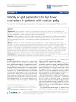
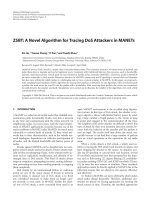
definition of each AP location is shown schematically in Fig. 1.
The anatomic regions of the successful ablation sites were analyzed by two independent observers. In case of any disagreement
between the two observers, a third independent observer decided
which of the suggested anatomic regions should be chosen.
2.5. Electrocardiographic analysis
In all patients, standard 12-lead ECGs were recorded during
sinus rhythm at a paper speed of 25 mm/s, one day prior to the
ablation procedure. During sinus rhythm, the following measurements were obtained: (1) the peak amplitude of the R- and
S-waves in leads V1, V2, and aVF; and (2) the R/S ratio, calculated
as the R-wave amplitude divided by the S-wave amplitude in each
lead. If there was no visible S wave, the S-wave amplitude was
defined as 0.1 mV.
Fig. 1. Anatomic definition of accessory pathway location. A schematic diagram of
the heart from the left anterior oblique projection shows the relation among the
tricuspid annulus (TA), mitral annulus (MA), His bundle (HIS), coronary sinus
(CS), and the anatomic locations of the accessory pathways. Accessory pathway
locations are divided into five main regions, which are defined by double
lines. Abbreviations: LA: left anterior; LL: left lateral; LP: left posterior; LPL: left
posterolateral; MS: midseptal; PS: posteroseptal; RA: right anterior; RAS: right
anteroseptal; RL: right lateral; RP: right posterior; and RPL: right posterolateral.
2.6. Statistical analysis
We used a Bayesian analysis with standard definitions for sensitivity, specificity, positive predictive value, and negative predictive
value. The overall accuracy of the algorithm was calculated as a
weighted average.
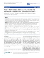
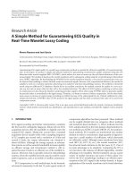
Fig. 2. Dot-plots showing R/S ratios of the initial 88 patients in each accessory pathway location. The dotted lines indicate the optimal cut-off value of the R/S ratio in each
lead. (A) The LA/LL and LPL/LP regions were associated with an R/S ratio Z 0.5 in lead V1. (B) The LA/LL, LPL/LP, and MS/PS regions were associated with an R/S ratio Z 0.5 in
lead V2. (C) The superior portion of the free wall APs (LA/LL and RAS/RA/RL regions) was associated with an R/S ratio Z 1 in lead aVF. On the other hand, the inferior portion
(LPL/LP and RPL/RP regions) was associated with an R/S ratio o 1 in lead aVF. Abbreviations are the same as in Fig. 1.
N. Taguchi et al. / Journal of Arrhythmia 30 (2014) 439–443
3. Results
3.1. Accessory pathway locations
AP locations were determined based on successful ablation
sites. Of the initial 88 patients, 48 were classified as being within
the LA/LL region, seven within the LPL/LP region, nine within the
MS/PS region, 12 within the RPL/RP region, and 12 within the RAS/
RA/RL region. Of the nine patients classified within the MS/PS
region, one was right midseptal, four were right posteroseptal, and
four were left posteroseptal. There were no oblique accessory
pathways crossing the anatomic regions defined in this study.
3.2. ECG algorithm development
The R/S ratios in leads V1, V2, and aVF were examined in each
successful ablation site. There was considerable overlap in the R/S
ratios between some contiguous sites, including LA and LL; LPL
and LP; MS and PS; RPL and RP; RAS, RA, and RL. For this reason,
pairs of contiguous successful ablation sites were grouped
together into five main regions in the analysis. Dot-plots of the
R/S ratios in leads V1, V2, and aVF are shown in Fig. 2. Among the
initial 88 patients, all 55 with left free wall APs including the LA/LL
and LPL/LP regions had an R/S ratio Z0.5 in lead V1. Of the 48
patients classified as LA/LL region, 47 (98%) had an R/S ratio Z 1 in
lead aVF. On the other hand, all seven patients classified as LPL/PL
region had an R/S ratio o1 in lead aVF. All nine patients classified
as right-and-left MS/PS region had an R/S ratio o 0.5 in lead V1,
and Z 0.5 in lead V2. Of 12 patients classified as RAS/RA/RL region,
10 (83%) had R/S ratios o0.5 in leads V1 and V2, and Z1 in lead
aVF. Finally, nine (75%) of 12 patients classified as RPL/PL region
441
had R/S ratios o0.5 in leads V1 and V2, and o 1 in lead aVF. Based
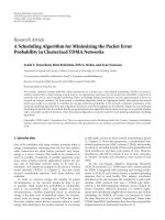
on these results, a new ECG algorithm was developed using only
the R/S ratios in leads V1, V2, and aVF, and is shown schematically
in Fig. 3. The distribution of the AP locations and the accuracy
of this ECG algorithm in each region are summarized in Table 1.
This ECG algorithm correctly identified the AP locations in 82
(93%) of the 88 patients, and is described as follows:
Step 1: The R/S ratio in lead V1 is examined. If the R/S ratio in
lead V1 is 0.5 or more, the AP is located in the free wall region
of the mitral annulus (LA/LL or LPL/LP region). Proceed
to Step 2.
If the R/S ratio in lead V1 is less than 0.5, the AP is located in the
free wall region of the tricuspid annulus or septum. Proceed to
Step 3.
Step 2: The R/S ratio in lead aVF is examined. If the R/S ratio in
lead aVF is 1 or more, the AP is located in the LA/LL region. If it
is less than 1, the AP is located in the LPL/LP region.
Step 3: The R/S ratio in lead V2 is examined. If the R/S ratio in
lead V2 is 0.5 or more, the AP is located in the left or right
MS/PS region. If the R/S ratio in lead V2 is less than 0.5, the AP
is located in the RAS/RA/RL region or the RPL/RP region.
Proceed to Step 4.
Step 4: The R/S ratio in lead aVF is examined. If the R/S ratio in
lead aVF is 1 or more, the AP is located in the RAS/RA/RL region.
If it is less than 1, the AP is located in the RPL/RP region.
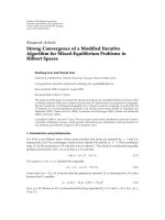
Representative 12-lead ECGs of the five main regions are
shown in Fig. 4.
3.3. ECG algorithm validation
The ECG algorithm was prospectively tested in 54 consecutive
patients to assess its accuracy in predicting the successful ablation
site. There were no oblique accessory pathways crossing the
anatomic regions defined in this study. The distribution of the
AP locations in these patients and the relationship between the
predicted location and the actual location are shown in Table 2.
The ECG algorithm correctly identified the AP locations in 51 (94%)
of the 54 patients (sensitivity: 94%, specificity: 98%, positive
predictive value: 92%, and negative predictive value: 98%).
4. Discussion
4.1. Main findings
Fig. 3. Stepwise ECG algorithm for the determination of accessory pathway
location. Abbreviations are the same as in Fig. 1.
In this study, we analyzed R/S ratios in only three leads (V1, V2,
and aVF), and developed a simple ECG algorithm which could
localize the APs in the five regions (LA/LL, LPL/LP, MS/PS, RPL/RP,
Table 1
Correlation between the predicted accessory pathway location (ECG algorithm) and the actual location based on ablation site.
Ablation site
LA/LL
LPL/LP
MS/PS
RPL/RP
RAS/RA/RL
Total
n
48
7
9
12
12
88
Predicted location
LA/LL
LPL/LP
47
1
7
Accuracy
MS/PS
9
2
2
RPL/RP
9
RAS/RA/RL
1
10
Sens (%)
Spec (%)
PPV (%)
NPV (%)
98
100
100
75
83
93
100
99
95
100
99
99
100
88
69
100
91
95
98
100
100
96
97
98
LA: left anterior; LL: left lateral; LPL: left posterolateral; LP: left posterior; MS: midseptal; PS: posteroseptal; RPL: right posterolateral; RP: right posterior; RAS: right
anteroseptal; RA: right anterior; RL: right lateral; Sens: sensitivity; Spec: specificity; PPV: positive predictive value; and NPV: negative predictive value.
442
N. Taguchi et al. / Journal of Arrhythmia 30 (2014) 439–443
Fig. 4. Representative 12-lead ECGs of the different accessory pathways. (A) In a case with the LA/LL accessory pathway, the R/S ratios were 0.5 or more in lead V1, and 1 or
more in lead aVF. This case was successfully ablated in the LL region. (B) In a case with the LPL/LP accessory pathway, the R/S ratios were 0.5 or more in lead V1, and less than
1 in lead aVF. This case was successfully ablated in the LPL region. (C) In a case with the MS/PS accessory pathway, the R/S ratios were less than 0.5 in lead V1, and 0.5 or more
in lead V2. This case was successfully ablated in the left PS region. (D) In a case with the RPL/RP accessory pathway, the R/S ratios were less than 0.5 in leads V1 and V2, and
less than 1 in lead aVF. This case was successfully ablated in the RPL region. (E) In a case with the RAS/RA/RL accessory pathway, the R/S ratios were less than 0.5 in leads V1
and V2, and 1 or more in lead aVF. This case was successfully ablated in the RAS region. Abbreviations are the same as in Fig. 1.
Table 2
Correlation between the predicted accessory pathway location (ECG algorithm) and the actual location based on ablation site.
Ablation site
LA/LL
LPL/LP
MS/PS
RPL/RP
RAS/RA/RL
Total
n
22
10
11
7
4
54
Predicted location
LA/LL
LPL/LP
21
1
10
1
Accuracy
MS/PS
RPL/RP
RAS/RA/RL
10
7
1
3
Sens (%)
Spec (%)
PPV (%)
NPV (%)
95
100
91
100
75
94
100
95
98
98
98
98
100
83
91
88
75
92
97
100
98
100
98
98
Data were obtained from 54 patients (prospective analysis).
LA: left anterior; LL: left lateral; LPL: left posterolateral; LP: left posterior; MS: midseptal; PS: posteroseptal; RPL: right posterolateral; RP: right posterior; RAS: right
anteroseptal; RA: right anterior; RL: right lateral; Sens: sensitivity; Spec: specificity; PPV: positive predictive value; and NPV: negative predictive value.
and RAS/RA/RL). The ECG algorithm was 93% accurate in the
retrospective analysis, and 94% accurate in the prospective assessment. Therefore, this ECG algorithm can provide a rapid and
accurate assessment of the AP locations as one follows a simple
flowchart.
4.2. Localization of the left free wall, right free wall and septal
accessory pathways
In previous studies [5,9,10] positive QRS polarity or an R/S ratio
Z1 in lead V1 was used for identifying left free wall APs. However,
we found that there were nine (16%) cases with an R/S ratio o1 in
lead V1 among the 55 patients with left free wall APs of the
retrospective group. Therefore, we used the optimal cut-off value
of an R/S ratio Z0.5 in lead V1, which yielded 100% sensitivity in
both, the retrospective and prospective groups.
The R/S ratio in lead V2 also had an essential role in differentiating the midseptal and posteroseptal APs from the right free
wall and right anterior septal APs in this study. Chiang et al. [11]
previously reported that an R/S ratio Z1 in lead V2 was a useful
marker for identifying the right and left posteroseptal APs, and left
free wall APs. Iturralde et al. [9] and d'Avila et al. [10] also reported
that the right posteroseptal APs were associated with positive QRS
polarity in lead V2. However, we found one right posteroseptal
and two left posteroseptal cases with an R/S ratio o1 in lead V2 in
the retrospective group. Therefore, we used the optimal cut-off
value of an R/S ratio Z0.5 in lead V2 for differentiating the
midseptal and posteroseptal APs from the right free wall and right
anterior septal APs, and this yielded 100% sensitivity in both, the
retrospective and prospective groups.
Anatomically, the location of the tricuspid annulus is more
anterior to, and to the right of the mitral annulus. In addition, the
right free wall aspect of the tricuspid annulus is more anterior to,
and to the right of the atrioventricular septum. A possible reason
for the larger R/S ratio in lead V2 of the midseptal and posteroseptal APs was the more posterior location of the atrioventricular
septum, and the larger R/S ratio in lead V1 of the left free wall APs
was due to the more posterior location of the left free wall aspect
of the mitral annulus.
In this study, the R/S ratio in lead aVF was useful for differentiating the anterior and lateral APs from the posterolateral and
posterior APs in both, right and left free wall APs.
N. Taguchi et al. / Journal of Arrhythmia 30 (2014) 439–443
4.3. Comparison with the algorithm based on the delta wave
morphology
Delta wave morphology reflects the ventricular attachment
site of the AP, and the R/S ratio also depends on the AP location.
The R/S ratio can change with the timing differences between AP
conduction and atrioventricular nodal conduction, so that the
analysis of delta wave morphology may identify the AP location
more accurately. However, because there were very few cases with
impaired atrioventricular node conduction, the region-specific R/S
ratios could be obtained constantly in this study. As it is occasionally difficult to accurately determine the delta wave morphology,
we believe that the algorithm based on the R/S ratio may be more
convenient.
4.4. Clinical implications
This ECG algorithm allows rapid assessment of the AP locations
by following a simple flowchart and it will help in the development of a strategy for catheter ablation.
4.5. Study limitations
A limitation of this study is that the sample size in the
prospective assessment was small. Therefore, further prospective
investigation is needed to fully determine the reliability of this
new algorithm. Another limitation of this ECG algorithm is the
difficulty of differentiating the detailed AP localization around the
paraseptal regions. Although we tried to develop an algorithm that
could subdivide the paraseptal regions into the detailed septal
regions, it was impossible to do so using only the R/S ratios.
Another limitation is that the accuracy of this algorithm may be
affected by the magnitude of the delta wave, cardiac rotation,
bundle branch block, and axis deviation. Of the nine mispredicted
patients, three patients had counter-clockwise cardiac rotation,
two had left axis deviation, and one had incomplete right bundle
branch block in the post-ablation ECG. The remaining three
patients had no ECG abnormality in the post-ablation ECG (data
not shown). We speculate that the presence of counter-clockwise
cardiac rotation and right bundle branch block are associated with
greater R/S ratios in lead V1 and V2 in the preablation ECG. On the
other hand, clockwise cardiac rotation and left bundle branch
block may be associated with smaller R/S ratios in leads V1 and V2.
Left axis deviation may be associated with a smaller R/S ratio in
443
lead aVF. However, it is difficult to know these ECG abnormalities
prior to successful ablation.
5. Conclusion
We present a simple ECG algorithm that can rapidly identify
the AP localization with high sensitivity and specificity.
Conflict of interest
The authors declare that there were no conflicts of interest.
No financial support was received for this study.
References
[1] Jackman WM, Wang XZ, Friday KJ, et al. Catheter ablation of accessory
atrioventricular pathways (Wolff-Parkinson-White syndrome) by radiofrequency current. N Engl J Med 1991;324:1605–11.
[2] Warin JF, Haissaguerre M, D'Ivernois C, et al. Catheter ablation of accessory
pathways: technique and results in 248 patients. Pacing Clin Electrophysiol
1990;13:1609–14.
[3] Kay GN, Epstein AE, Dailey SM, et al. Role of radiofrequency ablation in the
management of supraventricular arrhythmias: experience in 760 consecutive
patients. J Cardiovasc Electrophysiol 1993;4:371–89.
[4] Iesaka Y, Takahashi A, Chun YH, et al. Radiofrequency catheter ablation of
atrioventricular accessory pathways in Wolff-Parkinson-White syndrome with
drug-refractory and symptomatic supraventricular tachycardia—its high effectiveness irrespective of accessory pathway location and properties. Jpn Circ
J 1994;58:767–77.
[5] Arruda MS, McClelland JH, Wang X, et al. Development and validation of an
ECG algorithm for identifying accessory pathway ablation site in WolffParkinson-White syndrome. J Cardiovasc Electrophysiol 1998;9:2–12.
[6] Fitzpatrick AP, Gonzales RP, Lesh MD, et al. New algorithm for the localization
of accessory atrioventricular connections using a baseline electrocardiogram.
J Am Coll Cardiol 1994;23:107–16.
[7] Lindsay BD, Crossen KJ, Cain ME. Concordance of distinguishing electrocardiographic features during sinus rhythm with the location of accessory pathways
in the Wolff-Parkinson-White syndrome. Am J Cardiol 1987;59:1093–102.
[8] Milstein S, Sharma AD, Guiraudon GM, et al. An algorithm for the electrocardiographic localization of accessory pathways in the Wolff-ParkinsonWhite syndrome. Pacing Clin Electrophysiol 1987;10:555–63.
[9] Iturralde P, Araya-Gomez V, Colin L, et al. A new ECG algorithm for the
localization of accessory pathways using only the polarity of the QRS complex.
J Electrocardiol 1996;29:289–99.
[10] d'Avila A, Brugada J, Skeberis V, et al. A fast and reliable algorithm to localize
accessory pathways based on the polarity of the QRS complex on the surface
ECG during sinus rhythm. Pacing Clin Electrophysiol 1995;18:1615–27.
[11] Chiang CE, Chen SA, Teo WS, et al. An accurate stepwise electrocardiographic
algorithm for localization of accessory pathways in patients with WolffParkinson-White syndrome from a comprehensive analysis of delta waves
and R/S ratio during sinus rhythm. Am J Cardiol 1995;76:40–6.