Plans for a complete beekeeping system 1975
Bạn đang xem bản rút gọn của tài liệu. Xem và tải ngay bản đầy đủ của tài liệu tại đây (1.25 MB, 21 trang )
MICROFICHE
REFERENCE
LIBRARY
A project of Volunteers in Asia
lete
.
Beekeeoma
Published by:
Garden Way Publishing
Ferry Road
Charlotte,
VT 05445
This publication
Reproduced
USA
is out of print
by permission
Svstm
in 1983.
of Garden Way Publishing.
Reproduction
of this microfiche
document in any
form is subject to the same restrictions
as those
of the original
document.
PLP;NS
0C
FOQ
A
1975 GARDEN WAY RESEARCH
C~AABEOTTE,VT,0544-s
-:
4vI
c
.
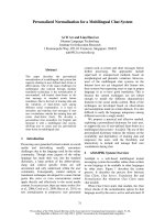
BEE SMOKER
Dse any can with a tight fitting
lid.
(canisters
from a hardware store
Solder a section of 3/4" tubing,
24" long through the lid
. make good smokers.)
at a 45 degree angle,
(not critical)
and a section of tube about the same
length through the can itself
&out 3/4" above the bottom with an inch projecttwo $" holes directly
above for the 2+ x $" bolts
ing out of the can. Drill
as shown.
The front and back of the bellows can be any wood 3/8" thick by 5" x 7%".
Drill
a 3/W hole to line up with the tube and holes for.*"
bolts as shown.
Cut a section of bed spring and fasten to the same piece with staples.
Bolt
to can as shown.
Cut vinyl or
front and back as
3%" at top.)
Cut
trim w&h $" wide
steel
The "G%ate", can be m@&by.punchAng
a number of holes in disc of sheet
cut to fit inside the can. Support with wire legs as shown.
If
supply
leatherette
3$" wide and 26" long.
Position
the bellows
shown in the cross section.
(That is 1" apart at bottom and
this material
to fit,
overlapping
about 1".
Glue to blocks,
metal strips named with 3/4" nails every inch.
you choose not to make your own smoker,
atalogs
quite inexpensively.
tney are available
in most bee
BEEGLOVEZZ
1
A.
Obtain a pair of comfortable
heavy duty cotton gloves and stitch
up two
loose fitting
"sleeves"
which will extend about halfway up your forearms.
These sleeves &otid
be medium weight canvas , and have elastic
sewn into the
open end. In use, the "sleeves"
should extend over whatever you're wearing
(shirt
or jacket)
and the elastic
should be tight enough to be "bee tight".
With confidence
without being stung.
and experience,
you should
be able to go without
gloves
SMOICER.
- -
-
--.
.
RUBEE BANDOQELAST/CC~BD
The center section is made
of plastic
window screen
ani3
the top and bottom sections of
mosquito netting
cut to the
in
r
.- COED
around a rubber band or a coil df several
strands of elastic
cord so that the top
section fits tightly
around a straw hat.
The
lower seam should be made wide enough to take a l/SO
diameter cord about 8' long.
Cord should be crossed
across your chest, the ends brought around your back
azd tied in front.
Make sure there are no spaces large
enough for bees to get inside!
.
.
SHALL0 W
SUPEE
- PLAN DUE To ?-HE
BEST 70 8UY
7HfSPA@
BROOQ
CFI14M03EQ
REVEPSIBIE
BOTTOM
BOARD
'
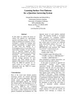
BEE HIVE CONSTRUcTfON
Use any 3/4" soft wood such as pine, basswood, or spruce.
Three quarter
- ti exterior
grade plywood can be substituted
for brood chamber and supers, as
-zg as you thoroughly
fill
and seal all the edges.
No!rB:
Gill
to
Dimensions
keep bees from
fill
are all
quite
working efficiently
the space with
critical
- too little
space between frames
whil &e too much will encourage the bees
comb.
BROODCHAMBER: Finger joints
although a dadc
are recommended for strength,
and rabbet joint can be substituted,
as well as a simple lap joint,
(pg. 5).
To make a finger joint,
set 3/4" wide dado saw to 3/4" high.
Make a cut near
the end of a 3i4” board about 3" x 16".
Insert a 3/4" x 3/4" x 1%" guide block
in this cut ( pg. 4 1 and nail in place.
Move board along the f-ace of the miter
gauge so the next cut is exactly
3;'4" from the guide block.
Check for accuracy,
and clamp in place on the face plate of the miter gauge.
Make the second cut
3/4" x 3/4".
This jig is then used to make finger joints.
First,
stand
side
on edge touching
inside face of guide block (the face nearest the dado blade).
Make first cut, then hook this slot over guide block, make next cut and so on.
In cutting
the opposite end, make suze
notches match.
Cut the notches in
tks side. pieces following
the same procedure,
but acre
that the first
cut
is made so that when the side and end are assembled, the bottom edge is even.
Assemble the frame and mark the top edge of each end in which the 7/X"
x 3/4
deep rsbbet is to be cut.
Note the top vfinger” edge of each side runs past
the ends to contain the rabbet.
Separate,
cut rabbets in ends and rip to 9+"
width removing stock from bottom edge of brood chamber.
Shallow supers are
of the same length and width as brood frame, but are only 6" high.
Follow same
procedure as above for finger joints.
NOTE: Since no metal strips
are used along
sabbet on shallow supers, rabbet is only S/8" deep.
Rip to final width of 5 11/16"
raoving
stock from bottom edge.
(Shallow supers are becoming more or less standard, as a deep super full of honey and bees can weigh fifty
to sixty pounds.
Since these are not too easy to handle, most hobby beekeepers are going to shallow
supers.
If you want to build deep supers, they are constnacted
the same way as
brood chambers.)
grips 3" deep as shown on all four sides.
Use aluminum strips
steel strips
in rabbet.
These strips
allow frames to be
from the brood chamber far easier.
Cut finger
narrow
or
galvanized
removed
fail
brood
chambers and supers
together
with
galvanized
nails.
BOTTOMBOARD: Soliid wood can be substituted
for plywood.
It is important
that
the f/8" and 3/8" dimensions be maintained
so if a thickness
other than 3/8"
is used, add the difference
to the total width of the sides and end pieces.
Nail
with galvanized
nails,
and glue with waterproof
glue.
TOP COVER: Finger joints
may be cut
overlapping
joints
may be substituted.
5 to 6" wide and one piece 18" x 5'r
lap joint,
the length of the end is
rip to 2 l/8" width.
After the top
*
I
the same way as the brood chamber, or simple
You'll
need one picse of pine, 21 3/4" x
to 6" wide.
(If you decide on a simple overonly 164" long.)
After finger joints
are cut,
cover
is assembled with glue and nails,
, /._
,,
I ~’
-
‘.
‘~
--_I
b
.
cover with &.:vninum or galvanized
steel,
lapping
5/8" to 3/4" Lo provide a watertight
aver.
down over the side
at least
Masonite or plywood can be used. The critical
dimensions here ar--?
the outside dimensions and the 5/16"' thickness
of the edge strips.
Cut hole t,,
Glue edge strips
in place using waterproof
glue..
accept bee escape.
INNER COVER:
The frame ads must be 1 3/8" wide clear lumber (not a standard
FRA&END&
thi&ess.)
Dress or have lumber yard dress
2" x 10" lumber, (actual dimension
14" x 9%") to I .3/8" thick.
Method 1: Cut blocks to lengths shown (9 l/8" or
5 3/8" depending whether you are making brood frames or shallow frames.)
(1) Cut 3/4" slots in each end. Make several support blocks from some of the
1 3/8" stock.
Width and length are not critical,
but the 3/4" x 3/8" tongue
should be centered exactly on the 1 3/8" dimension.
(2) Secure blocks and
clamp assembly in vise or secure to bench top by tacking cleats around the
assembly.
(3) Remove stock with router as shown in 2. Alternate
method:
With support block in one end make :aultiple
cuts over dado head to remave the
Slice blocks to 5/16" thick and drill
l/8" holes for support wires,
stock.
and then cut or sand shoulder
as shown on full-size
patterns.
Also smooth any
rough areas.
.
Method 2: : Rip 5/16" x 1 3/8" strips
and cut to lengths required
(either
9 l/8"
or 5 3/8").
Stack pieces and clamp together.
Cut 3/4" x 3/8" deep slots
centered at each end. Using support blocks at each end, follow instructions
in step 3 &bove to reduce the 1 3/8' to the 1 l/8" wide area.
Another alternative wou&d be to cut each strip individually
on a band saw using a master
template.
'
FRAMETOP: Pip stock to 7/8" x 1" dimensions.
Cut to 19" length.
(1)
+" deep not@ 1" from each end. Remove 5" x 1" block either
with a wood
or by sawing.
(2) Cut 5/16" notches for end frames, checking with frame
for proper fit.
(3) Using a saw blade with a thin kerf make two length
cuts to remove strip as shown in cross section.
Save strip to use later
fastening
foundation
in place.
cut
chisel
ends
wise
for
FRAME BOTTOM:Cut strips
17 5/8" x 3/4" as shown. Make a saw cut in center
leaving as thin a web as possible.
Nail frame ends in place first
by driving
1" x 17 or 18 ga. wire nails down through the frame tops in two places at each
After bottom is nailed
end. Nail the frame bottoms to the ends with 1" nails.
in Place' thin web is removed with razor blade or sharp knife,
or separat? two
pieces and trim off web before nailing.
FounLtion
is slipped in through the
bottom and nailed in place with 4" nails throu*n the piece of stock saved in the
FRAME
TOP paragraph above.
--
.-
812300
CHAMBER
SCALE $11’
T
I
‘blla
$
I
Q
FULL s IZE cm55
SEcrroN
U~ENOS
I
I
OR cur
-
’
I
I
17
I
--V.-s
t
r&M
TO +FTEQ
/F AiECESSA
RY.
I
ii
;I
NIAK/U/L;
-
_-
~o/hi;V~
A
-
II
- ---
--
-~~~~---~~
A
I
--
---
-w---
m----s-
-JTUNCE
1LEDUCE R
--
OUTER
COVER
AT”
-----m
-mm---
--B
r
I
1
I
I
I'
,I
I
--
I
f
I
-
P
-
z&g
I
It
A.
111'
v
A
Ill
w
B--w----
-w---
,II \
IT---
L
I
I.
I
N
N
ER
COVER
, FULL
SIZE
PAHERt$s
oe
t.
\
/
;$D,
.m
-
-
@
ALT
HOLES
USE
DAD0
SLICE
EIpro
SAW.
TO&hIcK
~th%CUTtULENCq-H.
-
.
sHALLOW
1
SUPER
F. Se OF
PABOhr
2RooDCmMBER:men
as9eabme
chamber,
brood
be sure to nail
the rsbbeted~
as shown
in the sketch at right
with two Yely fins 1s"
wire
mil.9.
The thin
section in tha rabbeted
.ndS
gets
a lot of hard
usage, and must bo reinforced
this way
breaking.
-‘.,(__‘.,
.
to keep
it
from
\\XI
A
FRAMES
6QOOD
FRAhAE
PALL-T” ‘A’
SEE DETAIL
SHALLOW SUPEP
FEAME
NAIL iN 2 PLACES E//U
.
.
;.,.’
<~
1
.‘,’
i
f/W
FiZZAME -TOP C&X-TOM
L
1,_19”
I
I
-m ’
L
lZ
CQUSS
SECTION
FULL SIZE
Drill
this
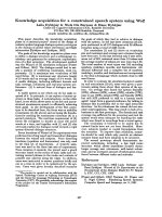
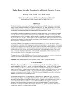
HONEYEXTRACTCRINSTRUCTIONS
This Honey Rxtractor
is designed to fit a standard, 20 gallon hot dipped galvanized
trash can.
or cut a hole as close to the bottom of the can as possible,
and solder a pipe nipple in place;
is the honey drain.
Check the can for water leaks.
Resolder joints
if necessary.
Hardware needed: l/2" diameter threaded rod , or threaded -both ends approximately
3';~ 26" long;
6-l/2"
hex nuts; 4-l/2" washers; Z-l/Z" I.D. ball bearings;
2-1/4" x 2" carriage bolts with wing-nuts;
a sheet of perforated
aluminum 19" x 32" (available
at most hardware stores in 24" x 36" sheets), or
All wood is to be hardwood; all wood to wood joints
should be glued with
galvanized hardware cloth.
waterproof glue.
STBP 1% (Refer to Figures 2 and 3.)
The top and bottom frames are made of 3/4" x 3/4" hardwood strips,
with half lapped joints,
(Bend the perforated
metal
Bend the perforated
sheet to fit inside these frames.
glued and screwed.
Fasten the perforated
metal inside the frames with 5/E"
over the square edge of a table or bench.)
Screw a round head screw, approximately
1 l/2" long, into each inside face of
sheet metal screws.
This will provide a support for the frames when they are placed in
the 3/4" x 3/4" hardwood strip.
The lower frame bottom is covered with plastic
window screen fastened along the edges of
the basket.
The open side of the perforated
metal
the lower frame with 3/4" x l/4" wood strips and 5/S" screws.
The two hardor hardware cloth (where the two ends join) should be "laced" together with wire loops.
with a l/2" hole in the center, and screwed
wood center blocks, 3/4" x 2 l/Z" x 11 l/2" are drilled
and glued across the center of the frames.
Four air deflectors
(cut from aluminum or from plastic
rain gutter)
are screwed to the leading
These deflectors
will direct the flow of the air and honey downward
edge of each side of the frame.
and help keep the honey from flying out of the extractor.
S!cp the rod through the hole in the 2 l/2" wide center blocks and lock in place with double
This 5/E" pronuts and washers leaving 5/E" of the rod projecting
below the bottom l/2" hex nut.
jection will slip into the bearing installed
in the next step.
STEP 2: (Refer to Figure 3.1
The bearing may be a metal sleeve
The bottom bearing block is now drilled
to take the bearing.
or ball bearing.
If you use a metal sleeve, it should be just large enough to slip over the end of
epoxy a tight fitting
sleeve over the threaded rod, and epoxy
the threaded rod.
If you prefer,
Ball bearings with a l/2" I.D. are
another larger sleeve in the bearing block to act as the bearing
After the bearing is
A sealed bearing is preferred.
available
at most industrial
supply companies.
It is
of the can, and epoxy in place.
installed
in the bearing block , center the block in the bottom
very important that the bearing block be centered.
STEP 3:
The top support (29" long x 2 l/2" x 3/4") is drilled
according to Figure 2. Drill
the center
startiug
10" from the center bearing
bearing hole 12" from one end. Cut the two l/4" x 2" slots,
hole.
The two blocks with the 3/E" x 3/8" notch and the carriage
bolts will be used to clamp the top
a bearing in
support to the top of the can; the notch will clamp around the lip of the can. Install
this top support in the same manner as the bottom bearing block.
STEP 4:
fitted
with a 3/4" hex socket to fit two l/2"
The power source can be a variable
speed drill,
nuts locked to the top end of the threaded rod, or a hand pulley system can be set up using pulleys
and a V-belt.
If you do decide to use the hand drive, you"11 need the following
hardware:
1 - 8" V-belt pulley with l/2" boretthis
may be a solid disc pulley 011 spoked)
1 - 2" V-belt pulley with l/2" bore
1 - 4" x l/2" bolt with 2 nuts
1 - 6" x l/2" bolt with 2 nuts
6-8 - l/2" washers
1 - l/2" lock washer
1 - 3 l/2" x 1" dowel drilled
with a l/2" hole
1 - V-belt approximately
31" long
2 - 1" wood screws
If you decide to use a variable
Note: Steps 5 through 8 are only for a hand powered extractor.
Speed drill,
lock 2 - l/2" nuts on the threaded rod, and skip to Step 9.
RORRYRXTRACTOR
Page 2
STEP 5:
Cut a l/2" x 2" slot in the top support.
One end of this slot is 6 l/2" from the center of the
long threaded rod; the other is 8 l/2" (this slot allows for adjustment of belt tension).
STEP: 6:
Notch the
Cut two pieces Of hardwood to fit the curvature of the inside rim of the 8" pulley.
hardwood so that it will "saddle" two of the spokes of the pulley.
Place the two pieces of hardwood
over the spokes and screw together with two wood screws.
(if a solid disc pulley is used, you may
eliminate
these blocks--however,
you'll
need to drill
a l/2" hole in the pulley for the purpose of
Drill
the hardwood blocks with a l/2" drill
and assemble the handle iu
installing
the handle.)
place.
The handle should move freely on the handle shaft (the 6" x l/2" bolt.)
STEP 7:
Place a flat washer on the 4" x l/2" bolt and slip this bolt into the hub of the 8" pulley.
Stack enough washers on the bolt so that the handle shaft will clear the top support when a l/2"
is threaded on the bolt.
Place the bolt in the 2" slot with a washer between the nut and wood.
another washer over the bolt and lock the entire assembly in place with another nut.
Make sure that
the pulley
rotates
freely
on its
shaft.
Adjust
the hex nuts if
it
nut
Slip
doesn't.
STEP 8:
bock the 2" diameter pulley in place on the long threaded rod by means of two hex nuts and a
lock vasher.
Rake sure the two pulleys line up. Install
the V-belt and adjust belt tension.
STEP 9:
Seal all of the wooden parts with a good grade of polyurethane
varnish,
and make sure the
varnish is thoroughly
dry before using the unit.
STEP 10:
For extracting,
clamp the long end of the bearing block to a bench, supporting
the bottom of
Or, place
Place a bucket under the honey drain to catch the honey.
the can on a stool or blocks.
the can on a stool or low platform and tie it down with elastic
load tie-downs or heavy screen door
springs hooked to the top support, and preferably
to the floor.
Deep (9 l/S") frames will fit each of the two long sides of the basket or one shallow frame
mill fit each of the four sides.
Some Suggestions About Extracting:
. Wake sure the honey is warm - warm honey will
risk of damaging the ccx
the extra&ox--place
egually
extract
fiiled
easier,
and vou will
frames opposite
run less
.
Try to balance
each other.
.
To keep from damaging the drawn comb, extract approximately
half of the honey on one side
Reverse the frames once
of the frames,
stop the basket, and extract the second side.
more for caplete
extraction.
.
When you're finished
extracting,
wash the extractor
down with hot water,
We recoasnend enclosing the unit
and store
the unit in a cool dry place.
plastic
bag to keep out insects and dust.
dry thoroughly
in a large
HONEY EXTRACTOR.
II I’
BILL
‘NUTE:ALL
‘.
;t,.
..
ABOVE
HAb?DWOOD.
^ ,I
I,
I
I
,I
OFMATERIALS.
I
Ii
I
II
i
I
I
I
ISEE NOT.. ;
1
I
I
I
-+i!$kig
!
iI
I
I
I
1 ‘4-jI
I
!
I
!
!
I
7
1
DEXWt~*
’
>~=RAME
f SEE DE-I-AI L)
$6E 8ELou/
DtlA
I
I L-t 1/
’
‘8
’
I
I
II
II
II
,,‘i
I
‘I
‘I
!I
I.!
*.
, .’
-. .. .
\
. . ..
‘*$$EEN I NG
DEFLECTOR
u
-\
BOTTOM
BEAPING
SCREW
1
7.
r ---
-,
HAND
1
L
DPIVE FOP EXTRACTOR,
CURVE 7’6
WOOb
WA&DL E
/
2’DIA
PL’UEY
.SUAW
\
I
,WASblEE
&D/AJW~LEY
WASHER
/Y-BELT
--
---
I
I
I1
r
I
I
II II I
II ,
F
7
//
eNU7=;WR5UE&