Điều chỉnh tốc độ máy nén lạnh bằng biến tần thông minh (KIMO)
Bạn đang xem bản rút gọn của tài liệu. Xem và tải ngay bản đầy đủ của tài liệu tại đây (449.41 KB, 6 trang )
KÄLTETECHNIK/VERDICHTER, FREQUENZUMRICHTER
Part 1: Gibson
Speed Control of
Refrigeration
Compressors with
intelligent Frequency
Inverters
Design considerations and experience
The control of suction pressure
by varying the speed of refrigeration compressors provides many
advantages.
If the installation is designed correctly then important considerations such as improved quality of
stored goods, energy saving, improved performance at light refrigeration loads and increased
working life can be easily
achieved.
1.1 Introduction
With
speed
control
refrigeration
compressors are operated outside the
normal area of operation defined and
specified by the manufacturer. It is
therefore very important to take certain
electrical and refrigeration technology
restraints into consideration.
This article will investigate compressor
packs with a "master" variable-speed
Dr. J.P. Gibson
KIMO Refrigeration HVAC Ltd., Fürth
Based on publication in © KI Luft- und Kältetechnik 1/2003
compressor connected in parallel with
several fixed speed compressors, see
Fig. 1.1.
The following abbreviations will be used
in this article:
VsC: Variable-speed Compressor
FsC: Fixed speed Compressor
FI: Frequency Inverter
In the systems which are described here,
Figure 1.1:
Refrigeration
system with a
Variable-speed
Compressor
(VsC) and two
Fixed-speed
Compressors
(FsCs).
Right:
FrigoPack
intelligent
Frequency
Inverter (FI)
1
KÄLTETECHNIK/VERDICHTER, FREQUENZUMRICHTER
Figure 1.2:
Mode of
operation of a
compressor
bank with
closed-loop
speed
controlled
master
compressor
speed. The mode of operation is described, for example, in [1].
This concept is based on the use of
intelligent FIs. These FI types can handle
the open-loop and closed-loop control
tasks in the compressor pack. The main
function of the intelligent FI is to maintain
the suction pressure constant by continually adapting the speed of the VsC.
As soon as the refrigeration power of the
VsC is no longer sufficient, an FsC is
switched-in, see Fig. 1.2. The system
automatically adjusts itself to the refrigeration power required. A typical system
utilizing this technology is shown in Fig.
1.3.
It is in principle possible to use two or
more VsCs in a refrigeration circuit.
However, in practice, such systems do
not provide any significant benefits so
that these systems will not be considered
in this article.
1.2 Advantages
Figure 1.3:
Typical
compressor
bank with
intelligent
frequency
inverter
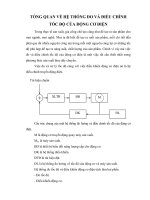
Figure 1.4: Measured characteristics in a real refrigeration system in
operation with closed-loop suction pressure control using intelligent
frequency inverters in comparison to operation with a conventional
compressor
multi-stage
an
electronic pack
FI iswith
used
to vary control
the
2
The following essential advantages are
obtained by continually adapting the
power of a compressor pack by controlling the speed of a VsC:
• Improved cooling quality by maintaining a constant suction pressure* (refer
to Fig. 1.3)
• Wider range of operation of the refrigeration power+ (refer to Fig. 1.5)
• Increased power by increasing the
speed of the VsC+ (refer to Fig. 1.7)
• Energy saving*
• Longer compressor lifetime +
• Better possibilities of providing monitoring, remote setting and diagnostics+
1.3 Closed-loop control range of
the refrigeration power
The comparison of a compressor pack
with the following units is shown in Fig.
1.5:
− 3 / 4 x FsC (conventional multi-stage
control)
− VsC (using a master compressor regulated using an FI) + 2 x FsCs.
At almost all operating points it is possible to provide the required refrigeration
power without having to frequently switch
the compressors on or off. This provides
the following decisive benefits:
• Fluctuation of the suction pressure,
caused by switching on or off a FsC
are minimized, refer to Fig. 1.4.
• The starting frequency of the compressors is significantly reduced, the life-
* This will be explained in considerable
detail in this article
+
This will be explained in more detail in
this article
Based on publication in © KI Luft- und Kältetechnik 1/2003
KÄLTETECHNIK/VERDICHTER, FREQUENZUMRICHTER
Temperatur(e) [°C]
Figure 1.5:
Comparison of a
compressor
bank with:
− 3 / 4 x FsC
(conventional
multi-step
control)
− VsC + 2 x FsCs
(FI controlled
master
compressor)
130
120
110
100
90
80
70
60
50
40
30
20
10
0
260%
240%
220%
200%
180%
160%
140%
120%
100%
80%
60%
40%
20%
0%
0
10
20
30
40
50
60
70
twind [°C]
fmech [%]
Vol [%]
Pe [%]
Qo/Pe
(COP) [%]
80
Frequenz/ Frequency [Hz]
Figure 1.6: Measurements made on a typical semi-hermetic reciprocating
compressor, Operating data: R404A, to = -10 °C, tc = +40 °C, toh = 25 °C
time and service/maintenance intervals
of the compressors is appropriately increased
• The evaporating temperature in the
system can be reduced
• The similar control quality can be
achieved using a lower number of larger compressors. (This minimizes the
installation costs.)
A control range of 0 ... 100 % would be
an optimum, but approximately 15 ... 100
% with a three compressor pack can be
cost-effectively realized. In practice, the
control range can be positively influenced by the following design features:
• Using three or more compressors in
the compressor pack
• Using a VsC with a low minimum
speed/frequency
• Using VsCs with the highest possible
maximum speed/frequency.
The associated problems will be discussed in more detail in the following
sections.
1.4 Minimum speed/frequency of
a VsC
Several years ago it was extremely difficult to obtain technical application data
at various speed/frequency points from
compressor manufacturers. This is understandable as the complex measurements required to type-test a compressor
are generally carried-out at 50 or 60 Hz.
Data which was available for operation at
other speeds were conservative general
data which were applicable for all compressors in a particular range of types.
Based on publication in © KI Luft- und Kältetechnik 1/2003
When precisely evaluating the permissible minimum speed of a certain compressor, the following questions/issues
must to be taken into consideration:
• Is the lubrication system able to fulfil
the required lubrication requirements ?
• Is the oil transport in the refrigeration
circuit sufficient for a reduced volume
flow ?
• Is the cooling of the motor winding of a
semi-hermetic VsC adequate
In order to evaluate the winding cooling
of a semi-hermetic VsC at reduced
speed, detailed measurements were
carried-out with typical compressors. The
evaluation of the measurement results of
a mid-range compressor is shown in Fig.
1.6.
The increase in the winding temperature
(twind) due to the reduced volume flow
at low speed/frequency can be clearly
seen.
Measures to ensure adequate winding
cooling are described in the following
section.
In the meantime, important manufacturers specify the minimum speed for VsC
operation of their reciprocating compressors in the range 20 ... 25 Hz. Very often
lower speed limits can be implemented
on request when the refrigeration-related
operating points are known. These lower
minimum speeds turn out to be
extremely advantageous.
1.5 Minimum refrigeration power
of a compressor pack
The minimum power of a compressor
bank is of particular importance, especially for supermarkets. In winter operation with the display cases and freezers
covered, the refrigeration power which is
required is relatively low. If the refrigeration system is over dimensioned compared with the required refrigeration
power, then, even when the VsC is
operated
at
the
minimum
speed/frequency, the low refrigeration
power required can only be achieved by
frequent on/off switching of the master
compressor.
This situation can be resolved by using a
VsC combined with capacity control
(cylinder-bank off loading). However this
requires a close coordination with the
compressor manufacturer and is not
possible with all compressors. Also a
very careful design of the refrigeration
circuit in connection with oil transport is
required.
3
KÄLTETECHNIK/VERDICHTER, FREQUENZUMRICHTER
Figure 1.7: Increased refrigeration
power
when
operating
a
compressor at 60 Hz using a
frequency inverter
1.6 Maximum speed/frequency of
a VsC (increased power)
It makes considerable sense to use an FI
to increase the maximum speed. Almost
all of the compressors are mechanically
designed for operation on 60 Hz electrical supplies. The refrigeration power of a
compressor can be easily increased by
approx. 20% - see Fig. 1.7.
With some compressors and with some
manufacturers it is often possible to
increase the speed even further. The
manufacturer must be contacted on a
case-for-case basis, specifying the
installation data. Operation up to 65 Hz
(approx. 30 % increase) or even up to 70
Hz (approx. 40 % increase) is often
possible. The application limits generally
lie in the area of thermal and flow-related
stressing in the discharge area of the
compressor.
The measurement results of a semihermetic compressor with a 400 V, 50
Hz motor winding are shown in Fig. 1.6.
The following should be noted:
• The speed (Fmech) above 50 Hz increases slightly lower than proportional
with the electrical frequency due to the
decreasing magnetic flux in the motor
(magnetic field weakening)
• The refrigeration-related power (Qo)
also increases slightly lower than proportional (approx. 30 % increased
power at 70 Hz compared with operation at 50 Hz)
• The temperature of the winding
(Twind) for operation at 60 Hz is lower
than that for operation at 50 Hz due to
the higher volume flow. However, this
is a characteristic of the compressor
being tested and cannot be used to
make a general statement
• For the compressor being tested, the
temperature at 70 Hz is insignificantly
higher than at 50 Hz in spite of the
magnetic field-weakening of the motor
These measurements and tests contradict the statement, which is often made
that operation in magnetic field-weakening above 50 Hz can be problematical. It
is incorrect to compare the thermal
behaviour
of
a
semi-hermetic
compressor motor with the thermal
behaviour of an industrial motor.
It is important to carefully evaluate the
maximum
permissible
upper
speed/frequency for the following reasons:
• The increased refrigeration power
provides the necessary reserves in
order to guarantee operation at the
peak refrigeration power (especially in
summer) without having to overdimension the compressors in the bank
• It is especially important to avoid overdimensioning the compressor bank,
especially for operation in the partial
load area (refer to the previous section).
1.7 Selecting the VsC
Positive experience has been gained
using the following compressor types:
− Semi-hermetic reciprocating compressors
− Screw compressors
− Fully hermetic reciprocating compressors from several manufacturers
− Scroll compressors from several
manufacturers
− Open and membrane type compressors.
The reciprocating compressor, which is
well-established worldwide, will now be
discussed in more detail.
Almost every manufacturer offers two
motor versions for every mechanical
frame size:
− Frame size with small motor (motor 2)
for operation with restricted suction
pressure or limited evaporation temperature
− Frame size with large motor (motor 1) also for operation with a higher evaporation temperature
The refrigeration-related performance
data of a typical semi-hermetic compressor, with different motor sizes, is schematically shown in Fig. 1.8.
When a compressor is operated with
speed/frequency control, this represents
an increased thermal load of the motor in
the limits operating range. At a lower
speed, the volume flow of refrigerant is
lower and at high speed, the current is
higher due to the magnetic field weakening. These potential problems can be
usually completely resolved by using the
compressor version with the larger
motor. This can be explained as follows:
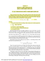
• At the critical operating points, the
electric power Pe drawn by the smaller
motor (M2) is significantly greater than
that of the larger motor (M1), see Fig.
1.9.
• The larger motor (M1) has a larger
internal surface for cooling with refrigerant (suction gas cooling).
• At the specified operating point (see
Fig. 1.9), the larger motor (M1) has a
lower loading which means that the
winding temperature increase is significantly lower.
The starting phase of a VsC is of decisive significance for disturbance-free
operation of the refrigeration system.
This especially applies to small compressors with two cylinders which require
a high starting torque. According to published information[2], torque reserves of
60 % are required for starting.
In the field, the compressors must be
able to start at high evaporation pressures. This means that it is not sufficient
to just consider a particular operating
point. Example: If the power is interrupted for several minutes, the evaporation pressure rapidly increases, the condensation pressure is still high – and the
required starting torque is now quite
significant.
Figure 1.8: Selecting the compressor
4
Based on publication in © KI Luft- und Kältetechnik 1/2003
KÄLTETECHNIK/VERDICHTER, FREQUENZUMRICHTER
1,00
R404A/30-M1
R404A/40-M1
0,90
R404A/50-M1
R404A/30-M2
0,80
R404A/40-M2
R404A/50-M2
Pe [pu]
0,70
R134a/50-M1
R134a/60-M1
0,60
R134a/70-M1
0,50
R134a/30-M2
R134a/40-M2
0,40
R134a/50-M2
0,30
0,20
0,00
2,00
4,00
6,00
8,00
10,00
Pressure / Druck Po [bara]
Figure 1.9: Relative electric power consumption Pe [pu] of a compressor as a function of the suction pressure Po when
using motors M2 (small) and M1 (large) at a condensing temperature of 30, 40, and 50 °C
If the compressor was not able to start,
then the motor winding does not have an
opportunity to cool down, the winding
temperature and therefore the winding
resistance significantly increase at each
start attempt. This generally ends in the
motor being tripped by its thermal thermistor monitoring. The motor winding is
significantly stressed.
The authors of this article recommend
that this technology is ONLY applied for
compressors with larger motors. The
additional costs for the compressor compared with the aggravation associated
with starting problems is negligible.
1.8 Selecting the rated power of
the FIs
The following criteria should be taken
into consideration:
• Required starting torque depending on
the compressor design and/or the
number of cylinders, refer for example
to [2]
• Possible measures to reduce the starting torque, e.g.:
− Start unloading arrangement (solenoid valve between the pressure and
suction sides of the compressor
opened during starting)
− Pressure limiter in the suction gas
line or at the evaporator
It is necessary to use what first appears
to be an over-dimensioned FI in order to
ensure reliable operation. This means
that the FI is mainly dimensioned to
achieve the correct starting torque.
There is nothing worse than a
compressor that cannot start. This
means that it does not make sense to
dimension an FI according to the rated
operating point as is generally the case
for fan and pump drives.
This new technology can only be widely
used if the necessary rated power of the
FI has been clearly defined. The authors
have drawn-up so-called compressor
"Cross Reference Lists" [3] for this purpose.
The required FIs for all common compressors summarized in the form of a
data base taking into account experience
gained in the field with "problematical
compressors".
1.9 Closed-loop control related
aspects
The integrated closed-loop suction pressure control ensures that the speed of
the VsC is set corresponding to the
actual refrigeration requirement. An FsC
is only switched in if the refrigeration
power of the VsC is no longer sufficient.
The integrated refrigeration software of
the FrigoPack system can control up to
Based on publication in © KI Luft- und Kältetechnik 1/2003
three FsCs. An external compressor
pack step-controller is not required and
is also not permissible (otherwise there
would be competing with the integrated
suction pressure controller). The minimum running and switch-off times,
specified by the various compressor
manufacturers, are taken into account in
the software. A block diagram of the
closed-loop control and common system
control are shown in Fig. 1.10.
In order to increase the system availability, a high-pressure limiter control function is optionally available. This is
extremely useful in the following cases:
• When the condensing power for high
refrigeration power is not sufficient in
summer
• There is dirt or obstructions in the
condenser
• One or more condenser fans have
failed
• The evaporator has ice build-up when
used in the heat pump mode
• Noise abatement restrictions only
allow the condenser, depending on the
time of day, to be used at reduced
speed
When a limit pressure is exceeded,
the speed of the VsC is
automatically reduced.
5
KÄLTETECHNIK/VERDICHTER, FREQUENZUMRICHTER
Figure 1.10: Block diagram of the closed-loop control system
1.10 Concept of the combined
compressor and condenser
control
It makes sense to integrate the condenser control
into the closed-loop
compressor control making use of the
existing signal from the high-pressure
sensor. This arrangement has the following advantages:
• Only one pressure sensor is required
for the high pressure
• The high-pressure limit and the condenser pressure setpoint can be set
together in the setup menu of the
compressor control software
• The condenser monitoring can be
integrated in the compressor control
1.11 Aspects of the electrical
installation
The use of state-of-the-art electronic FIs
brings with it new demands and requirements on the compressor installation.
The present situation is comparable with
the general introduction of variablespeed frequency inverters for driving
pumps and fans approximately 8 years
ago. Here are two important examples:
• The wiring of the electrical enclosure
and the installation must be carefully
conducted in accordance with EMC
recommendations
• The best closed-loop control only
functions correctly if the suction and
high pressure sensor signals are
available as noise-free actual values at
the controller input. It is important to
use only high-quality and highreliability pressure sensors
• Special EMC measures are necessary
so that the FIs do not disturb the
signals from the pressure transducers
6
In summary, there are several precautions which must be given careful consideration. There is a need to train refrigeration technicians and installers in
electrical engineering "knowhow", especially as far as EMC is concerned.
1.12 Remote diagnostics and
remote optimization
A refrigeration system can be remotely
supported when using an intelligent FI
with its new remote diagnostics and
remote optimization functionality. In this
case, two technologies come to the
forefront:
• The use of a fieldbus system such as
®
LonWorks , which allows data to be
remotely transferred via a modem or
through the Internet. These systems
are especially suitable to integrate the
refrigeration system monitoring
• The use of web-server based systems
to monitor the compressor bank and, if
required, the condenser.
The LonWorks® fieldbus system is especially interesting for future refrigeration
systems as all leading manufacturers of
refrigeration-related components and
control systems operate together to
®
define a global LonMark standard. This
work is well-progressed. The new technology of closed-loop speed control
compressors has already been taken
into account in this standard.
For approximately 5 years now, several
experienced companies have increasingly used this technology with considerable success. In the meantime, there are
over one thousand refrigeration and
climate control systems operational in
Germany and worldwide equipped with
KIMO FIs and which operate to the complete satisfaction of their users.
There is now a very close cooperation
between leading compressor manufacturers and the proponents of this technology. This means that there are common efforts to carry-out the necessary
training measures to widely establish this
technology.
This use of this new technology requires
a lot more system philosophy than with
previous conventional technologies. The
advantages of this new technology can
only be achieved by correctly designing
and installing the refrigeration, control
and electrical systems. This is the reason that system partners and distributors, with the right level of technical experience and knowhow, play an important role.
1.14 Summary and a look to the
future
FI technology is an essential component
of state-of-the-art refrigeration technology. Users who are both open and interested will soon get up to speed regarding
the requirements placed on the system
planning and implementation.
Experience and supplements to conventional refrigeration technology will be
discussed in the following articles.
1.15 Literature
[1] Arndt, A. Jantsch, U.: Digitale Regelung
von
VRF-Multisplit.
KI
Luftund
Kältetechnik 38 (2002) 10, S. 468
[2] Hendriks, M, R: Leistungsregelung von
Hubkolben- und Schraubenverdichtern.
Kälte Klima aktuell, 21 (2002) 6, S. 36-43
[3] KIMO
Refrigeration
HVAC
Ltd:
Compressor Cross Reference Lists
(available on enquiry)
1.16 Key words
Refrigeration
Compressor
Frequency Inverter
Control
Compressor Pack
Energy
1.13 Experience
The first attempts to use this technology
go back over 10 years.
Back then, the FIs which were available
were very expensive, prone to faults and
only had, to some extent, the necessary
control functionality.
Based on publication in © KI Luft- und Kältetechnik 1/2003