Solution manual mechanics of materials 8th edition hibbeler chapter 05
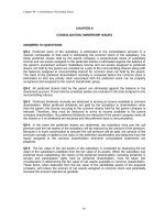
Bạn đang xem bản rút gọn của tài liệu. Xem và tải ngay bản đầy đủ của tài liệu tại đây (12.52 MB, 116 trang )
05 Solutions 46060
5/25/10
3:53 PM
Page 214
© 2010 Pearson Education, Inc., Upper Saddle River, NJ. All rights reserved. This material is protected under all copyright laws as they currently
exist. No portion of this material may be reproduced, in any form or by any means, without permission in writing from the publisher.
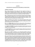
•5–1.
A shaft is made of a steel alloy having an allowable
shear stress of tallow = 12 ksi. If the diameter of the shaft is
1.5 in., determine the maximum torque T that can be
transmitted. What would be the maximum torque T¿ if a
1-in.-diameter hole is bored through the shaft? Sketch the
shear-stress distribution along a radial line in each case.
T
T¿
Allowable Shear Stress: Applying the torsion formula
tmax = tallow =
12 =
Tc
J
T (0.75)
p
2
(0.754)
T = 7.95 kip # in.
Ans.
Allowable Shear Stress: Applying the torsion formula
tmax = tallow =
12 =
T¿c
J
T¿ (0.75)
p
2
(0.754 - 0.54)
T¿ = 6.381 kip # in. = 6.38 kip # in.
tr = 0.5 in =
T¿r
=
J
6.381(0.5)
p
2
(0.754 - 0.54)
Ans.
= 8.00 ksi
214
05 Solutions 46060
5/25/10
3:53 PM
Page 215
© 2010 Pearson Education, Inc., Upper Saddle River, NJ. All rights reserved. This material is protected under all copyright laws as they currently
exist. No portion of this material may be reproduced, in any form or by any means, without permission in writing from the publisher.
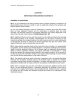
5–2. The solid shaft of radius r is subjected to a torque T.
Determine the radius r¿ of the inner core of the shaft that
resists one-half of the applied torque 1T>22. Solve the
problem two ways: (a) by using the torsion formula, (b) by
finding the resultant of the shear-stress distribution.
r¿
r
T
a)
tmax =
t =
Since t =
r¿ =
Tc
Tr
2T
= p 4 =
J
p r3
2 r
(T2 )r¿
p
2
(r¿)4
=
T
p(r¿)3
T
r¿ 2T
=
a
b
r pr3
p(r¿)3
r¿
t
;
r max
r
1
= 0.841 r
Ans.
24
r
2
b)
r¿
dT = 2p
L0
r
2
r¿
dT = 2p
L0
r
2
L0
tr2 dr
L0
r
tmax r2 dr
L0 r
r¿
dT = 2p
r 2T 2
a 3 br dr
L0 r pr
r¿
4T
T
= 4
r3 dr
2
r L0
r¿ =
r
1
Ans.
= 0.841r
24
215
05 Solutions 46060
5/25/10
3:53 PM
Page 216
© 2010 Pearson Education, Inc., Upper Saddle River, NJ. All rights reserved. This material is protected under all copyright laws as they currently
exist. No portion of this material may be reproduced, in any form or by any means, without permission in writing from the publisher.
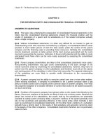
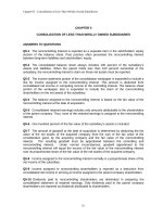
5–3. The solid shaft is fixed to the support at C and
subjected to the torsional loadings shown. Determine the
shear stress at points A and B and sketch the shear stress on
volume elements located at these points.
10 kNиm
C
A
50 mm
The internal torques developed at Cross-sections pass through point B and A are
shown in Fig. a and b, respectively.
The polar moment of inertia of the shaft is J =
p
(0.0754) = 49.70(10 - 6) m4. For
2
point B, rB = C = 0.075 Thus,
tB =
4(103)(0.075)
TB c
= 6.036(106) Pa = 6.04 MPa
=
J
49.70(10 - 6)
Ans.
From point A, rA = 0.05 m.
tA =
TArA
6(103)(0.05)
= 6.036(106) Pa = 6.04 MPa.
=
J
49.70 (10 - 6)
216
Ans.
B
75 mm
4 kNиm
75 mm
05 Solutions 46060
5/25/10
3:53 PM
Page 217
© 2010 Pearson Education, Inc., Upper Saddle River, NJ. All rights reserved. This material is protected under all copyright laws as they currently
exist. No portion of this material may be reproduced, in any form or by any means, without permission in writing from the publisher.
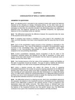
*5–4. The tube is subjected to a torque of 750 N # m.
Determine the amount of this torque that is resisted by the
gray shaded section. Solve the problem two ways: (a) by
using the torsion formula, (b) by finding the resultant of the
shear-stress distribution.
75 mm
100 mm
750 Nиm
25 mm
a) Applying Torsion Formula:
tmax =
Tc
=
J
750(0.1)
p
2
(0.14 - 0.0254)
tmax = 0.4793 A 106 B =
= 0.4793 MPa
T¿(0.1)
p
2
(0.14 - 0.0754)
T¿ = 515 N # m
Ans.
b) Integration Method:
r
t = a b tmax
c
dA = 2pr dr
and
dT¿ = rt dA = rt(2pr dr) = 2ptr2 dr
0.1m
T¿ =
L
2ptr2 dr = 2p
r
tmax a br2 dr
c
L0.075m
=
0.1m
2ptmax
r3 dr
c
L0.075m
=
2p(0.4793)(106) r4 0.1 m
c d2
0.1
4 0.075 m
= 515 N # m
Ans.
5–5. The copper pipe has an outer diameter of 40 mm and
an inner diameter of 37 mm. If it is tightly secured to the wall
at A and three torques are applied to it as shown, determine
the absolute maximum shear stress developed in the pipe.
tmax =
Tmax c
=
J
A
30 Nиm
90(0.02)
p
2
4
4
(0.02 - 0.0185 )
20 Nиm
= 26.7 MPa
Ans..
80 Nиm
217
05 Solutions 46060
5/25/10
3:53 PM
Page 218
© 2010 Pearson Education, Inc., Upper Saddle River, NJ. All rights reserved. This material is protected under all copyright laws as they currently
exist. No portion of this material may be reproduced, in any form or by any means, without permission in writing from the publisher.
5–6. The solid shaft has a diameter of 0.75 in. If it is
subjected to the torques shown, determine the maximum
shear stress developed in regions BC and DE of the shaft.
The bearings at A and F allow free rotation of the shaft.
F
E
D
C
B
(tBC)max =
35(12)(0.375)
TBC c
= 5070 psi = 5.07 ksi
= p
4
J
2 (0.375)
Ans.
(tDE)max =
25(12)(0.375)
TDE c
= 3621 psi = 3.62 ksi
= p
4
J
2 (0.375)
Ans.
A
35 lbиft
5–7. The solid shaft has a diameter of 0.75 in. If it is
subjected to the torques shown, determine the maximum
shear stress developed in regions CD and EF of the shaft.
The bearings at A and F allow free rotation of the shaft.
F
E
D
C
B
(tEF)max =
TEF c
= 0
J
(tCD)max =
25 lbиft
40 lbиft
20 lbиft
Ans.
A
25 lbиft
40 lbиft
20 lbиft
35 lbиft
15(12)(0.375)
TCD c
= p
4
J
2 (0.375)
= 2173 psi = 2.17 ksi
Ans.
218
05 Solutions 46060
5/25/10
3:53 PM
Page 219
© 2010 Pearson Education, Inc., Upper Saddle River, NJ. All rights reserved. This material is protected under all copyright laws as they currently
exist. No portion of this material may be reproduced, in any form or by any means, without permission in writing from the publisher.
300 Nиm
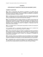
*5–8. The solid 30-mm-diameter shaft is used to transmit
the torques applied to the gears. Determine the absolute
maximum shear stress on the shaft.
500 Nиm
A
200 Nиm
Internal Torque: As shown on torque diagram.
C
Maximum Shear Stress: From the torque diagram Tmax = 400 N # m. Then, applying
torsion Formula.
400 Nиm
300 mm
abs =
tmax
Tmax c
J
400(0.015)
=
p
2
(0.0154)
Ans.
= 75.5 MPa
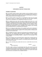
The shaft consists of three concentric tubes, each
made from the same material and having the inner and
outer radii shown. If a torque of T = 800 N # m is applied to
the rigid disk fixed to its end, determine the maximum shear
stress in the shaft.
500 mm
T ϭ 800 Nиm
ri ϭ 20 mm
ro ϭ 25 mm
2m
p
p
p
((0.038)4 - (0.032)4) + ((0.030)4 - (0.026)4) + ((0.025)4 - (0.020)4)
2
2
2
-6
ri ϭ 26 mm
ro ϭ 30 mm
4
J = 2.545(10 ) m
tmax =
B
400 mm
•5–9.
J =
D
800(0.038)
Tc
= 11.9 MPa
=
J
2.545(10 - 6)
Ans.
219
ri ϭ 32 mm
ro ϭ 38 mm
05 Solutions 46060
5/25/10
3:53 PM
Page 220
© 2010 Pearson Education, Inc., Upper Saddle River, NJ. All rights reserved. This material is protected under all copyright laws as they currently
exist. No portion of this material may be reproduced, in any form or by any means, without permission in writing from the publisher.
5–10. The coupling is used to connect the two shafts
together. Assuming that the shear stress in the bolts is
uniform, determine the number of bolts necessary to make
the maximum shear stress in the shaft equal to the shear
stress in the bolts. Each bolt has a diameter d.
T
R
r
n is the number of bolts and F is the shear force in each bolt.
T
T
F =
nR
T - nFR = 0;
T
tavg =
F
4T
nR
= p 2 =
A
( 4 )d
nRpd2
Maximum shear stress for the shaft:
tmax =
Tc
Tr
2T
= p 4 =
J
pr3
2r
4T
2T
=
nRpd2
p r3
tavg = tmax ;
n =
2 r3
Rd2
Ans.
5–11. The assembly consists of two sections of galvanized
steel pipe connected together using a reducing coupling at B.
The smaller pipe has an outer diameter of 0.75 in. and an inner
diameter of 0.68 in., whereas the larger pipe has an outer
diameter of 1 in. and an inner diameter of 0.86 in. If the pipe is
tightly secured to the wall at C, determine the maximum shear
stress developed in each section of the pipe when the couple
shown is applied to the handles of the wrench.
C
B
A
15 lb 6 in.
tAB =
tBC
Tc
=
J
Tc
=
=
J
8 in.
210(0.375)
p
2
(0.3754 - 0.344)
Ans.
15 lb
210(0.5)
p
2
= 7.82 ksi
(0.54 - 0.434)
= 2.36 ksi
Ans.
220
05 Solutions 46060
5/25/10
3:53 PM
Page 221
© 2010 Pearson Education, Inc., Upper Saddle River, NJ. All rights reserved. This material is protected under all copyright laws as they currently
exist. No portion of this material may be reproduced, in any form or by any means, without permission in writing from the publisher.
*5–12. The motor delivers a torque of 50 N # m to the shaft
AB. This torque is transmitted to shaft CD using the gears
at E and F. Determine the equilibrium torque T on shaft
CD and the maximum shear stress in each shaft. The
bearings B, C, and D allow free rotation of the shafts.
A
50 mm
30 mm
Equilibrium:
B
a + ©ME = 0;
a + ©MF = 0;
50 - F(0.05) = 0
F = 1000 N
35 mm
T¿
T¿ - 1000(0.125) = 0
T¿ = 125 N # m
C
E
125 mm
D
F
Ans.
Internal Torque: As shown on FBD.
Maximum Shear Stress: Applying torsion Formula.
(tAB)max =
50.0(0.015)
TAB c
= 9.43 MPa
= p
4
J
2 (0.015 )
Ans.
(tCD)max =
125(0.0175)
TCDc
= 14.8 MPa
= p
4
J
2 (0.0175 )
Ans.
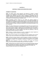
•5–13. If the applied torque on shaft CD is T¿ = 75 N # m,
determine the absolute maximum shear stress in each shaft.
The bearings B, C, and D allow free rotation of the shafts,
and the motor holds the shafts fixed from rotating.
A
50 mm
Equilibrium:
30 mm
a + ©MF = 0;
75 - F(0.125) = 0;
a + ©ME = 0;
600(0.05) - TA = 0
B
F = 600 N
35 mm
T¿
TA = 30.0 N # m
Internal Torque: As shown on FBD.
Maximum Shear Stress: Applying the torsion formula
(tEA)max =
30.0(0.015)
TEA c
= 5.66 MPa
= p
4
J
2 (0.015 )
Ans.
(tCD)max =
75.0(0.0175)
TCDc
= 8.91 MPa
= p
4
J
2 (0.0175 )
Ans.
221
C
E
125 mm
D
F
05 Solutions 46060
5/25/10
3:53 PM
Page 222
© 2010 Pearson Education, Inc., Upper Saddle River, NJ. All rights reserved. This material is protected under all copyright laws as they currently
exist. No portion of this material may be reproduced, in any form or by any means, without permission in writing from the publisher.
250 Nиm
5–14. The solid 50-mm-diameter shaft is used to transmit
the torques applied to the gears. Determine the absolute
maximum shear stress in the shaft.
75 Nиm
A
325 Nиm
150 Nи m
B
500 mm
The internal torque developed in segments AB , BC and CD of the shaft are shown
in Figs. a, b and c.
C
D
400 mm
500 mm
The maximum torque occurs in segment AB. Thus, the absolute maximum shear
stress occurs in this segment. The polar moment of inertia of the shaft is
p
J = (0.0254) = 0.1953p(10 - 6)m4. Thus,
2
A tmax B abs =
250(0.025)
TAB c
= 10.19(106)Pa = 10.2 MPa
=
J
0.1953p(10 - 6)
222
Ans.
05 Solutions 46060
5/25/10
3:53 PM
Page 223
© 2010 Pearson Education, Inc., Upper Saddle River, NJ. All rights reserved. This material is protected under all copyright laws as they currently
exist. No portion of this material may be reproduced, in any form or by any means, without permission in writing from the publisher.
5–15. The solid shaft is made of material that has an
allowable shear stress of tallow = 10 MPa. Determine the
required diameter of the shaft to the nearest mm.
15 Nиm
25 Nиm
A
30 Nиm
B
60 Nиm
C
70 Nиm
D
E
The internal torques developed in each segment of the shaft are shown in the torque
diagram, Fig. a.
Segment DE is critical since it is subjected to the greatest internal torque. The polar
p d 4
p 4
moment of inertia of the shaft is J =
a b =
d . Thus,
2 2
32
tallow
TDE c
=
;
J
d
70a b
2
10(106) =
p 4
d
32
d = 0.03291 m = 32.91 mm = 33 mm
223
Ans.
05 Solutions 46060
5/25/10
3:53 PM
Page 224
© 2010 Pearson Education, Inc., Upper Saddle River, NJ. All rights reserved. This material is protected under all copyright laws as they currently
exist. No portion of this material may be reproduced, in any form or by any means, without permission in writing from the publisher.
*5–16. The solid shaft has a diameter of 40 mm.
Determine the absolute maximum shear stress in the shaft
and sketch the shear-stress distribution along a radial line
of the shaft where the shear stress is maximum.
15 Nиm
25 Nиm
A
30 Nиm
B
The internal torque developed in each segment of the shaft are shown in the torque
diagram, Fig. a.
60 Nиm
C
70 Nиm
D
E
Since segment DE subjected to the greatest torque, the absolute maximum shear
p
stress occurs here. The polar moment of inertia of the shaft is J = (0.024)
2
= 80(10 - 9)p m4. Thus,
tmax =
70(0.02)
TDE c
= 5.57(106) Pa = 5.57 MPa
=
J
80(10 - 9)p
Ans.
The shear stress distribution along the radial line is shown in Fig. b.
•5–17.
The rod has a diameter of 1 in. and a weight of
10 lb/ft. Determine the maximum torsional stress in the rod
at a section located at A due to the rod’s weight.
4.5 ft
B
Here, we are only interested in the internal torque. Thus, other components of the
internal loading are not indicated in the FBD of the cut segment of the rod, Fig. a.
©Mx = 0;
TA - 10(4)(2) = 0
TA = 80 lb # ft a
The polar moment of inertia of the cross section at A is J =
12in
b = 960 lb # in.
1ft
p
(0.54) = 0.03125p in4.
2
Thus
tmax =
960 (0.5)
TA c
=
= 4889.24 psi = 4.89 ksi
J
0.03125p
Ans.
224
4 ft
A
1.5 ft
1.5 ft
05 Solutions 46060
5/25/10
3:53 PM
Page 225
© 2010 Pearson Education, Inc., Upper Saddle River, NJ. All rights reserved. This material is protected under all copyright laws as they currently
exist. No portion of this material may be reproduced, in any form or by any means, without permission in writing from the publisher.
5–18. The rod has a diameter of 1 in. and a weight of
15 lb/ft. Determine the maximum torsional stress in the rod
at a section located at B due to the rod’s weight.
4.5 ft
B
4 ft
Here, we are only interested in the internal torque. Thus, other components of the
internal loading are not indicated in the FBD of the cut segment of the rod, Fig. a.
©Mx = 0;
TB - 15(4)(2) = 0
TB = 120 lb # ft a
12 in
b = 1440 lb # in.
1ft
p
The polar moment of inertia of the cross-section at B is J = (0.54)
2
= 0.03125p in4. Thus,
tmax =
1440(0.5)
TB c
=
= 7333.86 psi = 7.33 ksi
J
0.03125p
Ans.
225
A
1.5 ft
1.5 ft
05 Solutions 46060
5/25/10
3:53 PM
Page 226
© 2010 Pearson Education, Inc., Upper Saddle River, NJ. All rights reserved. This material is protected under all copyright laws as they currently
exist. No portion of this material may be reproduced, in any form or by any means, without permission in writing from the publisher.
5–19. Two wrenches are used to tighten the pipe. If P =
300 N is applied to each wrench, determine the maximum
torsional shear stress developed within regions AB and BC.
The pipe has an outer diameter of 25 mm and inner
diameter of 20 mm. Sketch the shear stress distribution for
both cases.
P
B
Internal Loadings: The internal torque developed in segments AB and BC of the
pipe can be determined by writing the moment equation of equilibrium about the x
axis by referring to their respective free - body diagrams shown in Figs. a and b.
©Mx = 0; TAB - 300(0.25) = 0
TAB = 75 N # m
TBC = 150 N # m
Allowable Shear Stress: The polar moment of inertia of the pipe is
p
J =
A 0.01254 - 0.014 B = 22.642(10 - 9)m4.
2
A tmax B AB =
75(0.0125)
TAB c
= 41.4 MPa
=
J
22.642(10 - 9)
A tAB B r = 0.01 m =
A tmax B BC =
Ans.
TAB r
75(0.01)
= 33.1 MPa
=
J
22.642(10 - 9)
150(0.0125)
TBC c
= 82.8 MPa
=
J
22.642(10 - 9)
A tBC B r = 0.01 m =
Ans.
TBC r
150(0.01)
= 66.2 MPa
=
J
22.642(10 - 9)
The shear stress distribution along the radial line of segments AB and BC of the
pipe is shown in Figs. c and d, respectively.
226
A
250 mm
P
And
©Mx = 0; TBC - 300(0.25) - 300(0.25) = 0
250 mm
C
05 Solutions 46060
5/25/10
3:53 PM
Page 227
© 2010 Pearson Education, Inc., Upper Saddle River, NJ. All rights reserved. This material is protected under all copyright laws as they currently
exist. No portion of this material may be reproduced, in any form or by any means, without permission in writing from the publisher.
*5–20. Two wrenches are used to tighten the pipe. If the
pipe is made from a material having an allowable shear stress
of tallow = 85 MPa, determine the allowable maximum force
P that can be applied to each wrench. The pipe has an outer
diameter of 25 mm and inner diameter of 20 mm.
P
250 mm
C
B
A
250 mm
Internal Loading: By observation, segment BC of the pipe is critical since it is
subjected to a greater internal torque than segment AB. Writing the moment
equation of equilibrium about the x axis by referring to the free-body diagram
shown in Fig. a, we have
©Mx = 0; TBC - P(0.25) - P(0.25) = 0
TBC = 0.5P
Allowable Shear Stress: The polar moment of inertia of the pipe is
p
J =
A 0.01254 - 0.014 B = 22.642(10 - 9)m4
2
tallow =
TBC c
;
J
85(106) =
0.5P(0.0125)
22.642(10 - 9)
P = 307.93N = 308 N
Ans.
227
P
05 Solutions 46060
5/25/10
3:53 PM
Page 228
© 2010 Pearson Education, Inc., Upper Saddle River, NJ. All rights reserved. This material is protected under all copyright laws as they currently
exist. No portion of this material may be reproduced, in any form or by any means, without permission in writing from the publisher.
•5–21.
The 60-mm-diameter solid shaft is subjected to the
distributed and concentrated torsional loadings shown.
Determine the absolute maximum and minimum shear
stresses on the outer surface of the shaft and specify their
locations, measured from the fixed end A.
A
2 kNиm/m
1.5 m
1200 Nиm
C
The internal torque for segment BC is Constant TBC = 1200 N # m, Fig. a. However,
the internal for segment AB varies with x, Fig. b.
TAB - 2000x + 1200 = 0
TAB = (2000x - 1200) N # m
The minimum shear stress occurs when the internal torque is zero in segment AB.
By setting TAB = 0,
0 = 2000x - 1200
x = 0.6 m
Ans.
And
d = 1.5 m - 0.6 m = 0.9 m
Ans.
tmin = 0
Ans.
The maximum shear stress occurs when the internal torque is the greatest. This
occurs at fixed support A where
d = 0
Ans.
At this location,
(TAB)max = 2000(1.5) - 1200 = 1800 N # m
The polar moment of inertia of the rod is J =
tmax =
p
(0.034) = 0.405(10 - 6)p. Thus,
2
(TAB)max c
1800(0.03)
= 42.44(106)Pa = 42.4 MPa
=
J
0.405(10 - 6)p
228
Ans.
B
0.8 m
05 Solutions 46060
5/25/10
3:53 PM
Page 229
© 2010 Pearson Education, Inc., Upper Saddle River, NJ. All rights reserved. This material is protected under all copyright laws as they currently
exist. No portion of this material may be reproduced, in any form or by any means, without permission in writing from the publisher.
5–22. The solid shaft is subjected to the distributed and
concentrated torsional loadings shown. Determine the
required diameter d of the shaft to the nearest mm if the
allowable shear stress for the material is tallow = 50 MPa.
A
2 kNиm/m
1.5 m
1200 Nиm
C
The internal torque for segment BC is constant TBC = 1200 N # m, Fig. a. However,
the internal torque for segment AB varies with x, Fig. b.
TAB - 2000x + 1200 = 0 TAB = (2000x - 1200) N # m
For segment AB, the maximum internal torque occurs at fixed support A where
x = 1.5 m. Thus,
A TAB B max = 2000(1.5) - 1200 = 1800 N # m
Since A TAB B max 7 TBC, the critical cross-section is at A. The polar moment of inertia
p d 4
pd4
of the rod is J =
. Thus,
a b =
2 2
32
tallow =
Tc
;
J
50(106) =
1800(d>2)
pd4>32
d = 0.05681 m = 56.81 mm = 57 mm
229
Ans.
B
0.8 m
05 Solutions 46060
5/25/10
3:53 PM
Page 230
© 2010 Pearson Education, Inc., Upper Saddle River, NJ. All rights reserved. This material is protected under all copyright laws as they currently
exist. No portion of this material may be reproduced, in any form or by any means, without permission in writing from the publisher.
*5–24. The copper pipe has an outer diameter of 2.50 in.
and an inner diameter of 2.30 in. If it is tightly secured to the
wall at C and a uniformly distributed torque is applied to it
as shown, determine the shear stress developed at points A
and B. These points lie on the pipe’s outer surface. Sketch
the shear stress on volume elements located at A and B.
B
A
C
125 lbиft/ft
4 in.
9 in.
12 in.
Internal Torque: As shown on FBD.
Maximum Shear Stress: Applying the torsion formula
tA =
TA c
J
125.0(12)(1.25)
=
tB =
p
2
(1.254 - 1.154)
Ans.
= 3.02 ksi
Ans.
TB c
J
218.75(12)(1.25)
=
= 1.72 ksi
p
2
(1.254 - 1.154)
•5–25.
The copper pipe has an outer diameter of 2.50 in.
and an inner diameter of 2.30 in. If it is tightly secured to
the wall at C and it is subjected to the uniformly distributed
torque along its entire length, determine the absolute
maximum shear stress in the pipe. Discuss the validity of
this result.
B
A
C
125 lbиft/ft
4 in.
9 in.
Internal Torque: The maximum torque occurs at the support C.
Tmax = (125 lb # ft>ft)a
12 in.
25 in.
b = 260.42 lb # ft
12 in.>ft
Maximum Shear Stress: Applying the torsion formula
abs =
tmax
Tmax c
J
260.42(12)(1.25)
=
p
2
(1.254 - 1.154)
Ans.
= 3.59 ksi
According to Saint-Venant’s principle, application of the torsion formula should be
as points sufficiently removed from the supports or points of concentrated loading.
230
05 Solutions 46060
5/25/10
3:53 PM
Page 231
© 2010 Pearson Education, Inc., Upper Saddle River, NJ. All rights reserved. This material is protected under all copyright laws as they currently
exist. No portion of this material may be reproduced, in any form or by any means, without permission in writing from the publisher.
5–26. A cylindrical spring consists of a rubber annulus
bonded to a rigid ring and shaft. If the ring is held fixed and
a torque T is applied to the shaft, determine the maximum
shear stress in the rubber.
ro
ri
T
h
T
r
T
F
t =
=
=
A
2prh
2p r2 h
Shear stress is maximum when r is the smallest, i.e. r = ri. Hence,
tmax =
T
2p ri 2 h
Ans.
300 Nиm
5–27. The A-36 steel shaft is supported on smooth
bearings that allow it to rotate freely. If the gears are
subjected to the torques shown, determine the maximum
shear stress developed in the segments AB and BC. The
shaft has a diameter of 40 mm.
100 Nиm
A
The internal torque developed in segments AB and BC are shown in their
respective FBDs, Figs. a and b.
The polar moment of inertia of the shaft is J =
A tAB B max
200 Nиm
B
p
(0.024) = 80(10-9)p m4. Thus,
2
C
300(0.02)
TAB c
= 23.87(106)Pa = 23.9 MPa
=
=
J
80(10-9)p
A tBC B max =
200(0.02)
TBC c
= 15.92(106) Pa = 15.9 MPa
=
J
80(10-9)p
231
Ans.
Ans.
05 Solutions 46060
5/25/10
3:53 PM
Page 232
© 2010 Pearson Education, Inc., Upper Saddle River, NJ. All rights reserved. This material is protected under all copyright laws as they currently
exist. No portion of this material may be reproduced, in any form or by any means, without permission in writing from the publisher.
300 Nиm
*5–28. The A-36 steel shaft is supported on smooth
bearings that allow it to rotate freely. If the gears are
subjected to the torques shown, determine the required
diameter of the shaft to the nearest mm if tallover = 60 MPa.
100 Nиm
The internal torque developed in segments AB and BC are shown in their
respective FBDs, Fig. a and b
A
200 Nиm
B
Here, segment AB is critical since its internal torque is the greatest. The polar
p d 4
pd4
moment of inertia of the shaft is J =
. Thus,
a b =
2 2
32
C
tallow
TC
=
;
J
60(106) =
300(d>2)
pd4>32
d = 0.02942 m = 30 mm
Ans.
•5–29.
When drilling a well at constant angular velocity,
the bottom end of the drill pipe encounters a torsional
resistance TA . Also, soil along the sides of the pipe creates a
distributed frictional torque along its length, varying
uniformly from zero at the surface B to tA at A. Determine
the minimum torque TB that must be supplied by the drive
unit to overcome the resisting torques, and compute
the maximum shear stress in the pipe. The pipe has an outer
radius ro and an inner radius ri .
TA +
TB
B
L
1
t L - TB = 0
2 A
tA
2TA + tAL
TB =
2
Ans.
Maximum shear stress: The maximum torque is within the region above the
distributed torque.
tmax =
tmax =
Tc
J
(2TA + tAL)
] (r0)
2
p 4
4
(r
r
i)
2 0
[
(2TA + tAL)r0
=
Ans.
p(r40 - r4i )
232
A
TA
05 Solutions 46060
5/25/10
3:53 PM
Page 233
© 2010 Pearson Education, Inc., Upper Saddle River, NJ. All rights reserved. This material is protected under all copyright laws as they currently
exist. No portion of this material may be reproduced, in any form or by any means, without permission in writing from the publisher.
5–30. The shaft is subjected to a distributed torque along
its length of t = 110x22 N # m>m, where x is in meters. If the
maximum stress in the shaft is to remain constant at
80 MPa, determine the required variation of the radius c of
the shaft for 0 … x … 3 m.
x
x
T =
L
t dx =
Tc
t =
;
J
L0
10 x2dx =
6
80(10 ) =
3m
c
10 3
x
3
t ϭ (10x2) Nиm/m
3
(10
3 )x c
p
2
c4
c3 = 26.526(10-9) x3
c = (2.98 x) mm
Ans.
5–31. The solid steel shaft AC has a diameter of 25 mm and
is supported by smooth bearings at D and E. It is coupled to
a motor at C, which delivers 3 kW of power to the shaft
while it is turning at 50 rev>s. If gears A and B remove 1 kW
and 2 kW, respectively, determine the maximum shear stress
developed in the shaft within regions AB and BC. The shaft
is free to turn in its support bearings D and E.
TC =
3(103)
P
=
= 9.549 N # m
v
50(2p)
TA =
1
T = 3.183 N # m
3 C
3 kW
2 kW
25 mm
1 kW
A
D
(tAB)max =
3.183 (0.0125)
TC
= 1.04 MPa
= p
4
J
2 (0.0125 )
Ans.
(tBC)max =
9.549 (0.0125)
TC
= 3.11 MPa
= p
4
J
2 (0.0125 )
Ans.
233
B
E
C
05 Solutions 46060
5/25/10
3:53 PM
Page 234
© 2010 Pearson Education, Inc., Upper Saddle River, NJ. All rights reserved. This material is protected under all copyright laws as they currently
exist. No portion of this material may be reproduced, in any form or by any means, without permission in writing from the publisher.
*5–32. The pump operates using the motor that has a
power of 85 W. If the impeller at B is turning at 150 rev>min,
determine the maximum shear stress developed in the
20-mm-diameter transmission shaft at A.
150 rev/min
A
Internal Torque:
v = 150
rev 2p rad 1 min
= 5.00p rad>s
¢
≤
min
rev
60 s
P = 85 W = 85 N # m>s
T =
P
85
=
= 5.411 N # m
v
5.00p
Maximum Shear Stress: Applying torsion formula
tmax =
Tc
J
5.411 (0.01)
=
p
4
2 (0.01 )
= 3.44 MPa
Ans.
•5–33.
The gear motor can develop 2 hp when it turns at
450 rev>min. If the shaft has a diameter of 1 in., determine
the maximum shear stress developed in the shaft.
The angular velocity of the shaft is
v = ¢ 450
rev
2p rad
1 min
≤ ¢
≤ ¢
≤ = 15p rad>s
min
1 rev
60 s
and the power is
P = 2 hp ¢
550 ft # lb>s
≤ = 1100 ft # lb>s
1 hp
Then
T =
P
1100
12 in
=
= 23.34 lb # ft a
b = 280.11 lb # in
v
15p
1ft
The polar moment of inertia of the shaft is J =
tmax =
p
(0.54) = 0.03125p in4. Thus,
2
280.11 (0.5)
Tc
=
= 1426.60 psi = 1.43 ksi
J
0.03125p
Ans.
234
B
05 Solutions 46060
5/25/10
3:53 PM
Page 235
© 2010 Pearson Education, Inc., Upper Saddle River, NJ. All rights reserved. This material is protected under all copyright laws as they currently
exist. No portion of this material may be reproduced, in any form or by any means, without permission in writing from the publisher.
5–34. The gear motor can develop 3 hp when it turns at
150 rev>min. If the allowable shear stress for the shaft is
tallow = 12 ksi, determine the smallest diameter of the shaft
to the nearest 18 in. that can be used.
The angular velocity of the shaft is
v = a 150
rev
2p rad 1 min
ba
ba
b = 5p rad>s
min
1 rev
60 s
and the power is
P = (3 hp) a
550 ft # lb>s
b = 1650 ft # lb>s
1 hp
Then
T =
P
1650
12 in
=
= (105.04 lb # ft)a
b = 1260.51 lb # in
v
5p
1 ft
The polar moment of inertia of the shaft is J =
tallow =
Tc
;
J
12(103) =
p d 4
pd4
a b =
. Thus,
2 2
32
1260.51 (d>2)
pd4>32
d = 0.8118 in. =
7
in.
8
Ans.
5–35. The 25-mm-diameter shaft on the motor is made
of a material having an allowable shear stress of
tallow = 75 MPa . If the motor is operating at its maximum
power of 5 kW, determine the minimum allowable rotation
of the shaft.
Allowable Shear Stress: The polar moment of inertia of the shaft is
p
J =
A 0.01254 B = 38.3495(10-9) m4.
2
tallow =
Tc
;
J
75(106) =
T(0.0125)
38.3495(10-9)
T = 230.10 N # m
Internal Loading:
T =
P
;
v
230.10 =
5(103)
v
v = 21.7 rad>s
Ans.
235
05 Solutions 46060
5/25/10
3:53 PM
Page 236
© 2010 Pearson Education, Inc., Upper Saddle River, NJ. All rights reserved. This material is protected under all copyright laws as they currently
exist. No portion of this material may be reproduced, in any form or by any means, without permission in writing from the publisher.
*5–36. The drive shaft of the motor is made of a material
having an allowable shear stress of tallow = 75 MPa. If the
outer diameter of the tubular shaft is 20 mm and the wall
thickness is 2.5 mm, determine the maximum allowable
power that can be supplied to the motor when the shaft is
operating at an angular velocity of 1500 rev>min.
Internal Loading: The angular velocity of the shaft is
v = a 1500
rev
2p rad 1 min
ba
ba
b = 50p rad>s
min
1 rev
60 s
We have
T =
P
P
=
v
50p
Allowable Shear Stress: The polar moment of inertia of the shaft is
p
J = A 0.014 - 0.00754 B = 10.7379(10-9) m4.
2
tallow =
Tc
;
J
75(106) =
a
P
b(0.01)
50p
10.7379(10-9)
P = 12 650.25 W = 12.7 kW
Ans.
•5–37.
A ship has a propeller drive shaft that is turning at
1500 rev>min while developing 1800 hp. If it is 8 ft long and
has a diameter of 4 in., determine the maximum shear stress
in the shaft caused by torsion.
Internal Torque:
v = 1500
rev 2p rad 1 min
a
b
= 50.0 p rad>s
min 1 rev
60 s
P = 1800 hpa
T =
550 ft # lb>s
b = 990 000 ft # lb>s
1 hp
990 000
P
=
= 6302.54 lb # ft
v
50.0p
Maximum Shear Stress: Applying torsion formula
tmax =
6302.54(12)(2)
Tc
=
p 4
J
2 (2 )
= 6018 psi = 6.02 ksi
Ans.
236
05 Solutions 46060
5/25/10
3:53 PM
Page 237
© 2010 Pearson Education, Inc., Upper Saddle River, NJ. All rights reserved. This material is protected under all copyright laws as they currently
exist. No portion of this material may be reproduced, in any form or by any means, without permission in writing from the publisher.
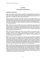
5–38. The motor A develops a power of 300 W and turns
its connected pulley at 90 rev>min. Determine the required
diameters of the steel shafts on the pulleys at A and B if the
allowable shear stress is tallow = 85 MPa.
60 mm
90 rev/min
A
B
150 mm
Internal Torque: For shafts A and B
vA = 90
rev 2p rad 1 min
a
b
= 3.00p rad>s
min
rev
60 s
P = 300 W = 300 N # m>s
P
300
=
= 31.83 N # m
vA
3.00p
TA =
vB = vA a
rA
0.06
b = 3.00pa
b = 1.20p rad>s
rB
0.15
P = 300 W = 300 N # m>s
TB =
P
300
=
= 79.58 N # m
vB
1.20p
Allowable Shear Stress: For shaft A
tmax = tallow =
85 A 106 B =
TA c
J
31.83 A d2A B
A B
p dA 4
2 2
dA = 0.01240 m = 12.4 mm
Ans.
For shaft B
tmax = tallow =
85 A 106 B =
TB c
J
79.58 A d2B B
A B
p dB 4
2 2
dB = 0.01683 m = 16.8 mm
Ans.
237