Solution manual mechanics of materials 8th edition hibbeler chapter 11
Bạn đang xem bản rút gọn của tài liệu. Xem và tải ngay bản đầy đủ của tài liệu tại đây (5.49 MB, 53 trang )
11 Solutions 46060
5/26/10
3:27 PM
Page 830
© 2010 Pearson Education, Inc., Upper Saddle River, NJ. All rights reserved. This material is protected under all copyright laws as they currently
exist. No portion of this material may be reproduced, in any form or by any means, without permission in writing from the publisher.
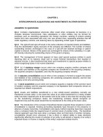
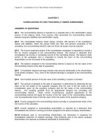
11–1. The simply supported beam is made of timber that
has an allowable bending stress of sallow = 6.5 MPa and an
allowable shear stress of tallow = 500 kPa. Determine its
dimensions if it is to be rectangular and have a height-towidth ratio of 1.25.
8 kN/m
2m
Ix =
1
(b)(1.25b)3 = 0.16276b4
12
Qmax = y¿A¿ = (0.3125b)(0.625b)(b) = 0.1953125b3
Assume bending moment controls:
Mmax = 16 kN # m
sallow =
Mmax c
I
6.5(106) =
16(103)(0.625b)
0.16276b4
b = 0.21143 m = 211 mm
Ans.
h = 1.25b = 264 mm
Ans.
Check shear:
Qmax = 1.846159(10 - 3) m3
I = 0.325248(10 - 3) m4
tmax =
VQmax
16(103)(1.846159)(10 - 3)
= 429 kPa 6 500 kPa‚ OK
=
It
0.325248(10 - 3)(0.21143)
830
4m
2m
11 Solutions 46060
5/26/10
3:27 PM
Page 831
© 2010 Pearson Education, Inc., Upper Saddle River, NJ. All rights reserved. This material is protected under all copyright laws as they currently
exist. No portion of this material may be reproduced, in any form or by any means, without permission in writing from the publisher.
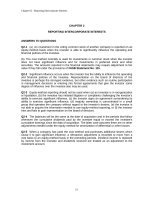
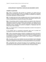
11–2. The brick wall exerts a uniform distributed load
of 1.20 kip>ft on the beam. If the allowable bending stress
is sallow = 22 ksi and the allowable shear stress is
tallow = 12 ksi, select the lightest wide-flange section with
the shortest depth from Appendix B that will safely support
the load.
1.20 kip/
4 ft
10 ft
ft
6 ft
b
Bending Stress: From the moment diagram, Mmax = 44.55 kip # ft. Assuming
bending controls the design and applying the flexure formula.
Sreq d =
=
44.55 (12)
= 24.3 in3
22
W12 * 22
A Sx = 25.4 in3, d = 12.31 in., tw = 0.260 in. B
V
for the W12 * 22 wide tw d
= 6.60 kip.
Shear Stress: Provide a shear stress check using t =
flange section. From the shear diagram, Vmax
tmax =
=
Vmax
tw d
6.60
0.260(12.31)
= 2.06 ksi 6 tallow = 12 ksi (O.K!)
Hence,
Use
9 in.
0.5 in.
Mmax
sallow
Two choices of wide flange section having the weight 22 lb>ft can be made. They
are W12 * 22 and W14 * 22. However, W12 * 22 is the shortest.
Select
0.5 in.
0.5 in.
Ans.
W12 * 22
831
11 Solutions 46060
5/26/10
3:27 PM
Page 832
© 2010 Pearson Education, Inc., Upper Saddle River, NJ. All rights reserved. This material is protected under all copyright laws as they currently
exist. No portion of this material may be reproduced, in any form or by any means, without permission in writing from the publisher.
11–3. The brick wall exerts a uniform distributed load
of 1.20 kip>ft on the beam. If the allowable bending stress
is sallow = 22 ksi, determine the required width b of the
flange to the nearest 14 in.
1.20 kip/
4 ft
10 ft
ft
6 ft
b
0.5 in.
0.5 in.
9 in.
0.5 in.
Section Property:
I =
1
1
(b) A 103 B (b - 0.5) A 93 B = 22.583b + 30.375
12
12
Bending Stress: From the moment diagram, Mmax = 44.55 kip # ft.
sallow =
22 =
Mmax c
I
44.55(12)(5)
22.583b + 30.375
b = 4.04 in.
Use
b = 4.25 in.
Ans.
832
11 Solutions 46060
5/26/10
3:27 PM
Page 833
© 2010 Pearson Education, Inc., Upper Saddle River, NJ. All rights reserved. This material is protected under all copyright laws as they currently
exist. No portion of this material may be reproduced, in any form or by any means, without permission in writing from the publisher.
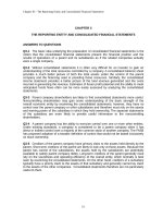
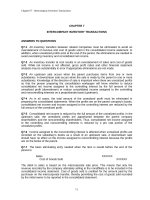
*11–4. Draw the shear and moment diagrams for the
shaft, and determine its required diameter to the nearest
1
4 in. if sallow = 7 ksi and tallow = 3 ksi. The bearings at A
and D exert only vertical reactions on the shaft. The loading
is applied to the pulleys at B, C, and E.
14 in.
20 in.
15 in.
12 in.
E
A
C
B
D
35 lb
80 lb
110 lb
sallow =
7(103) =
Mmax c
I
1196 c
p 4 ;
4 c
c = 0.601 in.
d = 2c = 1.20 in.
Use d = 1.25 in.
Ans.
Check shear:
2
tmax =
0.625
108(4(0.625)
Vmax Q
3p )(p)( 2 )
= 117 psi 6 3 ksi OK
=
p
4
It
4 (0.625) (1.25)
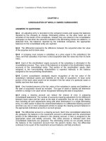
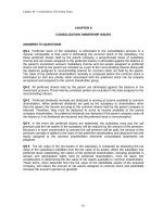
•11–5.
Select the lightest-weight steel wide-flange beam
from Appendix B that will safely support the machine loading
shown. The allowable bending stress is sallow = 24 ksi and
the allowable shear stress is tallow = 14 ksi.
2 ft
Bending Stress: From the moment diagram, Mmax = 30.0 kip # ft.
Assume bending controls the design. Applying the flexure formula.
Sreq¿d =
=
Select
W12 * 16
Mmax
sallow
30.0(12)
= 15.0 in3
24
A Sx = 17.1 in3, d = 11.99 in., tw = 0.220 in. B
V
for the W12 * 16 wide tw d
= 10.0 kip
Shear Stress: Provide a shear stress check using t =
flange section. From the shear diagram, Vmax
tmax =
=
Vmax
tw d
10.0
0.220(11.99)
= 3.79 ksi 6 tallow = 14 ksi (O.K!)
Hence,
Use
5 kip
5 kip
Ans.
W12 * 16
833
2 ft
5 kip
2 ft
5 kip
2 ft
2 ft
11 Solutions 46060
5/26/10
3:27 PM
Page 834
© 2010 Pearson Education, Inc., Upper Saddle River, NJ. All rights reserved. This material is protected under all copyright laws as they currently
exist. No portion of this material may be reproduced, in any form or by any means, without permission in writing from the publisher.
11–6. The compound beam is made from two sections,
which are pinned together at B. Use Appendix B and select
the lightest-weight wide-flange beam that would be safe for
each section if the allowable bending stress is sallow = 24 ksi
and the allowable shear stress is tallow = 14 ksi. The beam
supports a pipe loading of 1200 lb and 1800 lb as shown.
C
A
B
6 ft
Bending Stress: From the moment diagram, Mmax = 19.2 kip # ft for member AB.
Assuming bending controls the design, applying the flexure formula.
Sreq¿d =
=
Select
Mmax
sallow
19.2(12)
= 9.60 in3
24
A Sx = 10.9 in3, d = 9.87 in., tw = 0.19 in. B
W10 * 12
For member BC, Mmax = 8.00 kip # ft.
Sreq¿d =
=
Select
Mmax
sallow
8.00(12)
= 4.00 in3
24
A Sx = 5.56 in3, d = 5.90 in., tw = 0.17 in. B
W6 * 9
V
for the W10 * 12 widetw d
flange section for member AB. From the shear diagram, Vmax = 2.20 kip.
Shear Stress: Provide a shear stress check using t =
tmax =
=
Vmax
tw d
2.20
0.19(9.87)
= 1.17 ksi 6 tallow = 14 ksi (O.K!)
Use
Ans.
W10 * 12
For member BC (W6 * 9), Vmax = 1.00 kip.
tmax =
=
Vmax
tw d
1.00
0.17(5.90)
= 0.997 ksi 6 tallow = 14 ksi (O.K!)
Hence,
Use
1800 lb
1200 lb
W6 * 9
Ans.
834
6 ft
8 ft
10 ft
11 Solutions 46060
5/26/10
3:27 PM
Page 835
© 2010 Pearson Education, Inc., Upper Saddle River, NJ. All rights reserved. This material is protected under all copyright laws as they currently
exist. No portion of this material may be reproduced, in any form or by any means, without permission in writing from the publisher.
11–7. If the bearing pads at A and B support only vertical
forces, determine the greatest magnitude of the uniform
distributed loading w that can be applied to the beam.
sallow = 15 MPa, tallow = 1.5 MPa.
w
A
B
1m
1m
150 mm
25 mm
150 mm
25 mm
The location of c, Fig. b, is
y =
0.1625(0.025)(0.15) + 0.075(0.15)(0.025)
©yA
=
©A
0.025(0.15) + 0.15(0.025)
= 0.11875 m
I =
+
1
(0.025)(0.153) + (0.025)(0.15)(0.04375)2
12
1
(0.15)(0.0253) + 0.15(0.025)(0.04375)2
12
= 21.58203125(10 - 6) m4
Referring to Fig. b,
Qmax = y¿A¿ = 0.059375 (0.11875)(0.025)
= 0.176295313(10 - 4) m3
Referring to the moment diagram, Mmax = 0.28125 w. Applying the Flexure
formula with C = y = 0.11875 m,
sallow =
Mmax c
;
I
15(106) =
0.28125w(0.11875)
21.582(10 - 6)
W = 9.693(103) N>m
Referring to shear diagram, Fig. a, Vmax = 0.75 w.
tallow =
Vallow Qmax
;
It
1.5(106) =
0.75w C 0.17627(10 - 3) D
21.582(10 - 6)(0.025)
W = 6.122(103) N>m
= 6.12 kN>m (Control!)
Ans.
835
11 Solutions 46060
5/26/10
3:27 PM
Page 836
© 2010 Pearson Education, Inc., Upper Saddle River, NJ. All rights reserved. This material is protected under all copyright laws as they currently
exist. No portion of this material may be reproduced, in any form or by any means, without permission in writing from the publisher.
*11–8. The simply supported beam is made of timber that
has an allowable bending stress of sallow = 1.20 ksi and an
allowable shear stress of tallow = 100 psi. Determine its
smallest dimensions to the nearest 18 in. if it is rectangular
and has a height-to-width ratio of 1.5.
12 kip/ft
B
A
3 ft
3 ft
1.5 b
b
The moment of inertia of the beam’s cross-section about the neutral axis is
1
(b)(1.5b)3 = 0.28125b4. Referring to the moment diagram,
I =
12
Mmax = 45.375 kip # ft.
sallow =
Mmax c
;
I
1.2 =
45.375(12)(0.75b)
0.28125b4
b = 10.66 in
Referring to Fig. b, Qmax = y¿A¿ = 0.375b (0.75b)(b) = 0.28125b3. Referring to the
shear diagram, Fig. a, Vmax = 33 kip.
tmax =
Vmax Qmax
;
It
100 =
33(103)(0.28125b3)
0.28125b4(b)
b = 18.17 in (Control!)
Thus, use
b = 18
1
in
4
Ans.
836
11 Solutions 46060
5/26/10
3:27 PM
Page 837
© 2010 Pearson Education, Inc., Upper Saddle River, NJ. All rights reserved. This material is protected under all copyright laws as they currently
exist. No portion of this material may be reproduced, in any form or by any means, without permission in writing from the publisher.
•11–9.
Select the lightest-weight W12 steel wide-flange
beam from Appendix B that will safely support the loading
shown, where P = 6 kip. The allowable bending stress
is sallow = 22 ksi and the allowable shear stress is
tallow = 12 ksi.
P
P
9 ft
From the Moment Diagram, Fig. a, Mmax = 54 kip # ft.
Mmax
sallow
Sreq¿d =
54(12)
22
=
= 29.45 in3
Select W12 * 26
C Sx = 33.4 in3, d = 12.22 in and tw = 0.230 in. D
From the shear diagram, Fig. a, Vmax = 7.5 kip. Provide the shear-stress check
for W 12 * 26,
tmax =
=
Vmax
tw d
7.5
0.230(12.22)
= 2.67 ksi 6 tallow = 12 ksi (O.K!)
Hence
Use
Ans.
W12 * 26
837
6 ft
6 ft
11 Solutions 46060
5/26/10
3:27 PM
Page 838
© 2010 Pearson Education, Inc., Upper Saddle River, NJ. All rights reserved. This material is protected under all copyright laws as they currently
exist. No portion of this material may be reproduced, in any form or by any means, without permission in writing from the publisher.
11–10. Select the lightest-weight W14 steel wide-flange
beam having the shortest height from Appendix B that
will safely support the loading shown, where P = 12 kip.
The allowable bending stress is sallow = 22 ksi and the
allowable shear stress is tallow = 12 ksi.
P
P
9 ft
From the moment diagram, Fig. a, Mmax = 108 kip # ft.
Mmax
sallow
Sreq¿d =
108(12)
22
=
= 58.91 in3
Select W14 * 43
C Sx = 62.7 in3, d = 13.66 in and tw = 0.305 in. D
From the shear diagram, Fig. a, Vmax = 15 kip . Provide the shear-stress check
for W14 * 43 ,
tmax =
=
Vmax
tw d
15
0.305(13.66)
= 3.60 ksi 6 tallow = 12 ksi‚ (O.K!)
Hence,
Use
Ans.
W14 * 43
838
6 ft
6 ft
11 Solutions 46060
5/26/10
3:27 PM
Page 839
© 2010 Pearson Education, Inc., Upper Saddle River, NJ. All rights reserved. This material is protected under all copyright laws as they currently
exist. No portion of this material may be reproduced, in any form or by any means, without permission in writing from the publisher.
11–11. The timber beam is to be loaded as shown. If the ends
support only vertical forces, determine the greatest magnitude
of P that can be applied. sallow = 25 MPa, tallow = 700 kPa.
150 mm
30 mm
120 mm
40 mm
P
4m
A
y =
(0.015)(0.150)(0.03) + (0.09)(0.04)(0.120)
= 0.05371 m
(0.150)(0.03) + (0.04)(0.120)
I =
1
1
(0.150)(0.03)3 + (0.15)(0.03)(0.05371 - 0.015)2 +
(0.04)(0.120)3 +
12
12
B
(0.04)(0.120)(0.09 - 0.05371)2 = 19.162(10 - 6) m4
Maximum moment at center of beam:
Mmax =
P
(4) = 2P
2
Mc
;
I
s =
25(106) =
(2P)(0.15 - 0.05371)
19.162(10 - 6)
P = 2.49 kN
Maximum shear at end of beam:
Vmax =
P
2
VQ
;
t =
It
700(103) =
P 1
C (0.15 - 0.05371)(0.04)(0.15 - 0.05371) D
2 2
19.162(10 - 6)(0.04)
P = 5.79 kN
Thus,
P = 2.49 kN
Ans.
839
4m
11 Solutions 46060
5/26/10
3:27 PM
Page 840
© 2010 Pearson Education, Inc., Upper Saddle River, NJ. All rights reserved. This material is protected under all copyright laws as they currently
exist. No portion of this material may be reproduced, in any form or by any means, without permission in writing from the publisher.
*11–12. Determine the minimum width of the beam to
the nearest 14 in. that will safely support the loading of
P = 8 kip. The allowable bending stress is sallow = 24 ksi
and the allowable shear stress is tallow = 15 ksi.
P
6 ft
6 ft
6 in.
B
A
Beam design: Assume moment controls.
sallow =
Mc
;
I
24 =
48.0(12)(3)
1
3
12 (b)(6 )
b = 4 in.
Ans.
Check shear:
8(1.5)(3)(4)
VQ
= 0.5 ksi 6 15 ksi OK
= 1
3
It
12 (4)(6 )(4)
tmax =
•11–13.
Select the shortest and lightest-weight steel wideflange beam from Appendix B that will safely support the
loading shown.The allowable bending stress is sallow = 22 ksi
and the allowable shear stress is tallow = 12 ksi.
10 kip
6 kip
4 kip
A
B
4 ft
Beam design: Assume bending moment controls.
Sreq¿d =
60.0(12)
Mmax
=
= 32.73 in3
sallow
22
Select a W 12 * 26
Sx = 33.4 in3, d = 12.22 in., tw = 0.230 in.
Check shear:
tavg =
V
10.5
=
= 3.74 ksi 6 12 ksi
Aweb
(12.22)(0.230)
Use W 12 * 26
Ans.
840
4 ft
4 ft
4 ft
11 Solutions 46060
5/26/10
3:27 PM
Page 841
© 2010 Pearson Education, Inc., Upper Saddle River, NJ. All rights reserved. This material is protected under all copyright laws as they currently
exist. No portion of this material may be reproduced, in any form or by any means, without permission in writing from the publisher.
11–14. The beam is used in a railroad yard for loading and
unloading cars. If the maximum anticipated hoist load is
12 kip, select the lightest-weight steel wide-flange section
from Appendix B that will safely support the loading. The
hoist travels along the bottom flange of the beam,
1 ft … x … 25 ft, and has negligible size. Assume the beam
is pinned to the column at B and roller supported at A.
The allowable bending stress is sallow = 24 ksi and
the allowable shear stress is tallow = 12 ksi.
x
27 ft
A
B
12 kip
15 ft
C
Maximum moment occurs when load is in the center of beam.
Mmax = (6 kip)(13.5 ft) = 81 lb # ft
sallow =
M
;
S
24 =
81(12)
Sreq¿d
Sreq¿d = 40.5 in3
Select a W 14 * 30, Sx = 42.0 in3, d = 13.84 in, tw = 0.270 in.
At x = 1 ft, V = 11.56 kip
t =
11.36
V
=
= 3.09 ksi 6 12 ksi
Aweb
(13.84)(0.270)
Use W14 * 30
Ans.
841
11 Solutions 46060
5/26/10
3:27 PM
Page 842
© 2010 Pearson Education, Inc., Upper Saddle River, NJ. All rights reserved. This material is protected under all copyright laws as they currently
exist. No portion of this material may be reproduced, in any form or by any means, without permission in writing from the publisher.
11–15. The simply supported beam is made of timber that
has an allowable bending stress of sallow = 960 psi and an
allowable shear stress of tallow = 75 psi. Determine its
dimensions if it is to be rectangular and have a heightto-width ratio of 1.25.
5 kip/ft
6 ft
1
I =
(b)(1.25b)3 = 0.16276b4
12
Sreq¿d
b
Assume bending moment controls:
Mmax = 60 kip # ft
960 =
Mmax
Sreq¿d
60(103)(12)
0.26042 b3
b = 14.2 in.
Check shear:
tmax =
1.5(15)(103)
1.5V
=
= 88.9 psi 7 75 psi NO
A
(14.2)(1.25)(14.2)
Shear controls:
tallow =
6 ft
1.25 b
I
0.16276b4
=
=
= 0.26042b3
c
0.625b
sallow =
B
A
1.5(15)(103)
1.5V
=
A
(b)(1.25b)
b = 15.5 in.
Ans.
842
11 Solutions 46060
5/26/10
3:27 PM
Page 843
© 2010 Pearson Education, Inc., Upper Saddle River, NJ. All rights reserved. This material is protected under all copyright laws as they currently
exist. No portion of this material may be reproduced, in any form or by any means, without permission in writing from the publisher.
*11–16. The simply supported beam is composed of two
W12 * 22 sections built up as shown. Determine the
maximum uniform loading w the beam will support if
the allowable bending stress is sallow = 22 ksi and the
allowable shear stress is tallow = 14 ksi.
w
Section properties:
24 ft
For W12 * 22 (d = 12.31 in. Ix = 156 in4 tw = 0.260 in. A = 6.48 in2)
I = 2c 156 + 6.48a
S =
12.31 2
b d = 802.98 in4
2
I
802.98
=
= 65.23 in3
c
12.31
Maximum Loading: Assume moment controls.
M = sallowS(72 w)(12) = 22(65.23)
w = 1.66 kip>ft
Check Shear:
tmax =
Ans.
(Neglect area of flanges.)
12(1.66)
Vmax
= 3.11 ksi 6 tallow = 14 ksi OK
=
Aw
2(12.31)(0.26)
•11–17.
The simply supported beam is composed of two
W12 * 22 sections built up as shown. Determine if the beam
will safely support a loading of w = 2 kip>ft. The allowable
bending stress is sallow = 22 ksi and the allowable shear
stress is tallow = 14 ksi.
w
24 ft
Section properties:
For W 12 * 22 (d = 12.31 in.
Ix = 156 in4
tw = 0.260 in.
A = 6.48 in2)
I = 2[156 + 6.48(6.1552)] = 802.98 in4
S =
802.98
I
=
= 65.23 in3
c
12.31
Bending stress:
smax =
144 (12)
Mallow
=
= 26.5 ksi 7 sallow = 22 ksi
S
65.23
No, the beam falls due to bending stress criteria.
Check shear:
tmax =
Ans.
(Neglect area of flanges.)
Vmax
24
=
= 3.75 ksi 6 tallow = 14 ksi OK
Aw
2(12.31)(0.26)
843
11 Solutions 46060
5/26/10
3:27 PM
Page 844
© 2010 Pearson Education, Inc., Upper Saddle River, NJ. All rights reserved. This material is protected under all copyright laws as they currently
exist. No portion of this material may be reproduced, in any form or by any means, without permission in writing from the publisher.
11–18. Determine the smallest diameter rod that will
safely support the loading shown. The allowable bending
stress is sallow = 167 MPa and the allowable shear stress
is tallow = 97 MPa.
25 N/m
15 N/m
15 N/m
1.5 m
Bending Stress: From the moment diagram, Mmax = 24.375 N # m. Assume bending
controls the design. Applying the flexure formula.
sallow =
167 A 10
6
B =
Mmax c
I
24.375
p
4
A d2 B
A d2 B 4
d = 0.01141 m = 11.4 mm
Ans.
Shear Stress: Provide a shear stress check using the shear formula with
I =
p
A 0.0057074 B = 0.8329 A 10 - 9 B m4
4
Qmax =
4(0.005707) 1
c (p) A 0.0057062 B d = 0.1239 A 10 - 6 B m3
3p
2
From the shear diagram, Vmax = 30.0 N.
tmax =
=
Vmax Qmax
It
30.0 C 0.1239(10 - 6) D
0.8329 (10 - 9)(0.01141)
= 0.391 MPa 6 tallow = 97 MPa (O.K!)
844
1.5 m
11 Solutions 46060
5/26/10
3:27 PM
Page 845
© 2010 Pearson Education, Inc., Upper Saddle River, NJ. All rights reserved. This material is protected under all copyright laws as they currently
exist. No portion of this material may be reproduced, in any form or by any means, without permission in writing from the publisher.
11–19. The pipe has an outer diameter of 15 mm.
Determine the smallest inner diameter so that it will safely
support the loading shown. The allowable bending stress
is sallow = 167 MPa and the allowable shear stress is
tallow = 97 MPa.
25 N/m
15 N/m
15 N/m
1.5 m
Bending Stress: From the moment diagram, Mmax = 24.375 N # m. Q. Assume
bending controls the design. Applying the flexure formula.
sallow =
167 A 106 B =
Mmax c
I
24.375(0.0075)
p
4
C 0.00754 - A 2i B 4 D
d
di = 0.01297 m = 13.0 mm
Ans.
Shear Stress: Provide a shear stress check using the shear formula with
I =
p
A 0.00754 - 0.0064864 B = 1.0947 A 10 - 9 B m4
4
Qmax =
4(0.0075) 1
4(0.006486) 1
c (p) A 0.00752 B d c (p) A 0.0064862 B d
3p
2
3p
2
= 99.306 A 10 - 9 B m3
From the shear diagram, Vmax = 30.0 N. Q
tmax =
=
Vmax Qmax
It
30.0 C 99.306(10 - 9) D
1.0947(10 - 9)(0.015 - 0.01297)
= 1.34 MPa 6 tallow = 97 MPa (O.K!)
845
1.5 m
11 Solutions 46060
5/26/10
3:27 PM
Page 846
© 2010 Pearson Education, Inc., Upper Saddle River, NJ. All rights reserved. This material is protected under all copyright laws as they currently
exist. No portion of this material may be reproduced, in any form or by any means, without permission in writing from the publisher.
*11–20. Determine the maximum uniform loading w
the W12 * 14 beam will support if the allowable bending
stress is sallow = 22 ksi and the allowable shear stress is
tallow = 12 ksi.
w
10 ft
10 ft
From the moment diagram, Fig. a, Mmax = 28.125 w. For W12 * 14, Sx = 14.9 in3,
d = 11.91 in and tw = 0.200 in.
sallow =
22 =
Mmax
S
28.125 w (12)
14.9
Ans.
w = 0.9712 kip>ft = 971 lb>ft
From the shear diagram, Fig. a, Vmax = 7.5(0.9712) = 7.284 kip. Provide a shear
stress check on W12 * 14,
tmax =
=
Vmax
tw d
7.284
0.200(11.91)
= 3.06 ksi 6 tallow = 12 ksi (O.K)
846
11 Solutions 46060
5/26/10
3:27 PM
Page 847
© 2010 Pearson Education, Inc., Upper Saddle River, NJ. All rights reserved. This material is protected under all copyright laws as they currently
exist. No portion of this material may be reproduced, in any form or by any means, without permission in writing from the publisher.
•11–21.
Determine if the W14 * 22 beam will safely
support a loading of w = 1.5 kip>ft. The allowable bending
stress is sallow = 22 ksi and the allowable shear stress
is tallow = 12 ksi.
w
10 ft
10 ft
For W14 * 22, Sx = 29.0 in3, d = 13.74 in and tw = 0.23 in. From the moment
diagram, Fig. a, Mmax = 42.1875 kip # ft.
smax =
=
Mmax
S
42.1875(12)
29.0
= 17.46 ksi 6 sallow = 22 ksi (O.K!)
From the shear diagram, Fig. a, Vmax = 11.25 kip.
tmax =
=
Vmax
tw d
11.25
0.23(13.74)
= 3.56 ksi 6 tallow = 12 ksi (O.K!)
Based on the investigated results, we conclude that W14 * 22 can safely support
the loading.
847
11 Solutions 46060
5/26/10
3:27 PM
Page 848
© 2010 Pearson Education, Inc., Upper Saddle River, NJ. All rights reserved. This material is protected under all copyright laws as they currently
exist. No portion of this material may be reproduced, in any form or by any means, without permission in writing from the publisher.
11–22. Determine the minimum depth h of the beam to
the nearest 18 in. that will safely support the loading shown.
The allowable bending stress is sallow = 21 ksi and the
allowable shear stress is tallow = 10 ksi. The beam has a
uniform thickness of 3 in.
4 kip/ft
h
A
B
12 ft
The section modulus of the rectangular cross-section is
S =
I
=
C
1
12
(3)(h3)
h>2
= 0.5 h2
From the moment diagram, Mmax = 72 kip # ft.
Sreq¿d =
Mmax
sallow
0.5h2 =
72(12)
21
h = 9.07 in
Use
h = 9 18 in
Ans.
From the shear diagram, Fig. a, Vmax = 24 kip . Referring to Fig. b,
9.125 9.125
ba
b (3) = 31.22 in3 and
Qmax = y¿A¿ = a
4
2
1
I =
(3) A 9.1253 B = 189.95 in4 . Provide the shear stress check by applying
12
shear formula,
tmax =
=
Vmax Qmax
It
24(31.22)
189.95(3)
= 1.315 ksi 6 tallow = 10 ksi (O.K!)
848
6 ft
11 Solutions 46060
5/26/10
3:27 PM
Page 849
© 2010 Pearson Education, Inc., Upper Saddle River, NJ. All rights reserved. This material is protected under all copyright laws as they currently
exist. No portion of this material may be reproduced, in any form or by any means, without permission in writing from the publisher.
11–23. The box beam has an allowable bending stress
of sallow = 10 MPa and an allowable shear stress of
tallow = 775 kPa. Determine the maximum intensity w of the
distributed loading that it can safely support. Also, determine
the maximum safe nail spacing for each third of the length of
the beam. Each nail can resist a shear force of 200 N.
w
30 mm
250 mm
30 mm
150 mm
30 mm
Section Properties:
I =
1
1
(0.21) A 0.253 B (0.15) A 0.193 B = 0.1877 A 10 - 3 B m4
12
12
QA = y1 ¿A¿ = 0.11(0.03)(0.15) = 0.495 A 10 - 3 B m3
Qmax = ©y¿A¿ = 0.11(0.03)(0.15) + 0.0625(0.125)(0.06)
= 0.96375 A 10 - 3 B m3
Bending Stress: From the moment diagram, Mmax = 4.50w. Assume bending
controls the design. Applying the flexure formula.
sallow =
10 A 106 B =
Mmax c
I
4.50w (0.125)
0.1877 (10 - 3)
w = 3336.9 N>m
Shear Stress: Provide a shear stress check using the shear formula. From the shear
diagram, Vmax = 3.00w = 10.01 kN.
tmax =
=
Vmax Qmax
It
10.01(103) C 0.96375(10 - 3) D
0.1877(10 - 3)(0.06)
= 857 kPa 7 tallow = 775 kPa (No Good!)
Hence, shear stress controls.
tallow =
775 A 103 B =
Vmax Qmax
It
3.00w C 0.96375(10 - 3) D
0.1877(10 - 3)(0.06)
w = 3018.8 N>m = 3.02 kN>m
Ans.
Shear Flow: Since there are two rows of nails, the allowable shear flow is
2(200)
400
=
q =
.
s
s
849
6m
11 Solutions 46060
5/26/10
3:27 PM
Page 850
© 2010 Pearson Education, Inc., Upper Saddle River, NJ. All rights reserved. This material is protected under all copyright laws as they currently
exist. No portion of this material may be reproduced, in any form or by any means, without permission in writing from the publisher.
11–23.
Continued
For 0 … x 6 2 m and 4 m 6 x … 6 m, the design shear force is
V = 3.00w = 9056.3 N.
q =
VQA
I
9056.3 C 0.495(10 - 3) D
400
=
s
0.1877(10 - 3)
s = 0.01675 m = 16.7 mm
Ans.
For 2 m 6 x 6 4 m, the design shear force is V = w = 3018.8 N.
q =
VQA
I
3018.8 C 0.495(10 - 3) D
400
=
s
0.1877(10 - 3)
s = 0.05024 m = 50.2 mm
Ans.
850
11 Solutions 46060
5/26/10
3:27 PM
Page 851
© 2010 Pearson Education, Inc., Upper Saddle River, NJ. All rights reserved. This material is protected under all copyright laws as they currently
exist. No portion of this material may be reproduced, in any form or by any means, without permission in writing from the publisher.
*11–24. The simply supported joist is used in the
construction of a floor for a building. In order to keep the
floor low with respect to the sill beams C and D, the ends of
the joists are notched as shown. If the allowable shear stress
for the wood is tallow = 350 psi and the allowable bending
stress is sallow = 1500 psi, determine the height h that will
cause the beam to reach both allowable stresses at the same
time. Also, what load P causes this to happen? Neglect the
stress concentration at the notch.
P
2 in.
15 ft
B
h
15 ft
D
A
10 in.
C
Bending Stress: From the moment diagram, Mmax = 7.50P. Applying the flexure
formula.
Mmax c
I
salllow =
7.50P(12)(5)
1500 =
1
12
(2)(103)
P = 555.56 lb = 556 lb
Ans.
Shear Stress: From the shear diagram, Vmax = 0.500P = 277.78 lb. The notch is the
critical section. Using the shear formula for a rectangular section.
tallow =
350 =
3Vmax
2A
3(277.78)
2(2) h
h = 0.595 in.
Ans.
11–25. The simply supported joist is used in the
construction of a floor for a building. In order to keep the
floor low with respect to the sill beams C and D, the ends of
the joists are notched as shown. If the allowable shear stress
for the wood is tallow = 350 psi and the allowable bending
stress is sallow = 1700 psi, determine the smallest height h
so that the beam will support a load of P = 600 lb. Also,
will the entire joist safely support the load? Neglect the
stress concentration at the notch.
P
B
tallow =
1.5V
;
A
350 =
D
A
10 in.
600
= 300 lb
2
1.5(300)
(2)(h)
h = 0.643 in.
smax =
Ans.
4500(12)(5)
Mmax c
= 1620 psi 6 1700 psi OK
= 1
3
I
12 (2)(10)
Yes, the joist will safely support the load.
Ans.
851
h
15 ft
C
The reaction at the support is
2 in.
15 ft
11 Solutions 46060
5/26/10
3:27 PM
Page 852
© 2010 Pearson Education, Inc., Upper Saddle River, NJ. All rights reserved. This material is protected under all copyright laws as they currently
exist. No portion of this material may be reproduced, in any form or by any means, without permission in writing from the publisher.
11–26. Select the lightest-weight steel wide-flange beam
from Appendix B that will safely support the loading
shown. The allowable bending stress is sallow = 22 ksi and
the allowable shear stress is tallow = 12 ksi.
5 kip
18 kip ft
B
A
6 ft
From the moment diagram, Fig. a, Mmax = 48 kip # ft.
Sreq¿d =
=
Mmax
sallow
48(12)
22
= 26.18 in3
Select W 14 * 22 C Sx = 29.0 in3, d = 13.74 in. and tw = 0.230 in. D
From the shear diagram, Fig. a, Vmax = 5 kip. Provide the shear stress check for
W 14 * 22,
tmax =
=
Vmax
twd
5
0.230(13.74)
= 1.58 ksi 6 tallow = 12 ksi‚ (O.K!)
Use
Ans.
W14 * 22
W12 * 22 would work also.
852
12 ft
11 Solutions 46060
5/26/10
3:27 PM
Page 853
© 2010 Pearson Education, Inc., Upper Saddle River, NJ. All rights reserved. This material is protected under all copyright laws as they currently
exist. No portion of this material may be reproduced, in any form or by any means, without permission in writing from the publisher.
11–27. The T-beam is made from two plates welded
together as shown. Determine the maximum uniform
distributed load w that can be safely supported on the beam
if the allowable bending stress is sallow = 150 MPa and the
allowable shear stress is tallow = 70 MPa.
w
A
1.5 m
1.5 m
200 mm
20 mm
200 mm
20 mm
The neutral axis passes through centroid c of the beam’s cross-section. The location
of c, Fig. b, is
y =
0.21(0.02)(0.2) + 0.1(0.2)(0.02)
©yA
=
©A
0.02(0.2) + 0.2(0.02)
= 0.155 m
I =
1
(0.2)(0.023) + 0.2(0.02)(0.055)2
12
+
1
(0.02)(0.23) + 0.02(0.2)(0.055)2
12
= 37.667 (10 - 6) m4
Referring to Fig. b,
Qmax = y¿A¿ = 0.0775(0.155)(0.02)
= 0.24025(10 - 3) m3
Referring to the moment diagram, Mmax = -3.375 w. Applying the flexure
formula with C = y = 0.155 m,
sallow =
Mmax c
;
I
150(106) =
3.375 w (0.155)
37.667(10 - 6)
w = 10.80(103) N>m
= 10.8 kN>m (Control!)
Ans.
Referring to the shear diagram, Vmax = 1.5w.
tallow =
Vmax Qmax
;
It
70(106) =
1.5 w C 0.24025(10 - 3) D
37.667(10 - 6)(0.02)
w = 146.33(103) N>m
= 146 kN>m
853
11 Solutions 46060
5/26/10
3:27 PM
Page 854
© 2010 Pearson Education, Inc., Upper Saddle River, NJ. All rights reserved. This material is protected under all copyright laws as they currently
exist. No portion of this material may be reproduced, in any form or by any means, without permission in writing from the publisher.
*11–28. The beam is made of a ceramic material having
an allowable bending stress of sallow = 735 psi and an
allowable shear stress of tallow = 400 psi. Determine the
width b of the beam if the height h = 2b.
15 lb
10 lb
6 lb/in.
2 in.
6 in.
2 in.
h
b
Bending Stress: From the moment diagram, Mmax = 30.0 lb # in. Assume bending
controls the design. Applying the flexure formula.
sallow =
Mmax c
I
30.0
735 =
1
12
A 2b2 B
(b) (2b)3
b = 0.3941 in. = 0.394 in.
Ans.
Shear Stress: Provide a shear stress check using the shear formula for a rectangular
section. From the shear diagram, Vmax = 19.67 lb.
tmax =
=
3Vmax
2A
3(19.67)
2(0.3941)(2)(0.3941)
= 94.95 psi 6 tallow = 400 psi (O.K!)
854