Solution manual mechanics of materials 8th edition hibbeler chapter 14 part1
Bạn đang xem bản rút gọn của tài liệu. Xem và tải ngay bản đầy đủ của tài liệu tại đây (8.16 MB, 79 trang )
14 Solutions 46060_Part1
6/11/10
8:18 AM
Page 1159
© 2010 Pearson Education, Inc., Upper Saddle River, NJ. All rights reserved. This material is protected under all copyright laws as they currently
exist. No portion of this material may be reproduced, in any form or by any means, without permission in writing from the publisher.
sy
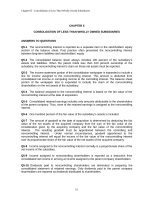
14–1. A material is subjected to a general state of plane
stress. Express the strain energy density in terms of the
elastic constants E, G, and n and the stress components sx ,
sy , and txy .
txy
sx
‘Strain Energy Due to Normal Stresses: We will consider the application of normal
stresses on the element in two successive stages. For the first stage, we apply only sx
on the element. Since sx is a constant, from Eq. 14-8, we have
s2x
s2x V
dV =
2E
Lv 2E
(Ui)1 =
When sy is applied in the second stage, the normal strain ex will be strained by
ex ¿ = -vey = -
vsy
E
. Therefore, the strain energy for the second stage is
(Ui)2 =
=
s2y
¢
Lv 2E
B
s2y
Lv 2E
+ sx ex ¿ ≤ dV
+ sx a -
vsy
E
b R dV
Since sx and sy are constants,
(Ui)2 =
V
(s2 - 2vsx sy)
2E y
Strain Energy Due to Shear Stresses: The application of txy does not strain the
element in normal direction. Thus, from Eq. 14–11, we have
(Ui)3 =
t2xy
Lv 2G
dV =
t2xy V
2G
The total strain energy is
Ui = (Ui)1 + (Ui)2 + (Ui)3
=
t2xy V
s2x V
V
+
(s2y - 2vsx sy) +
2E
2E
2G
=
t2xy V
V
(s2x + s2y - 2vsx sy) +
2E
2G
and the strain energy density is
t2xy
Ui
1
=
(s2x + s2y - 2vsx sy) +
V
2E
2G
Ans.
1159
14 Solutions 46060_Part1
6/11/10
8:18 AM
Page 1160
© 2010 Pearson Education, Inc., Upper Saddle River, NJ. All rights reserved. This material is protected under all copyright laws as they currently
exist. No portion of this material may be reproduced, in any form or by any means, without permission in writing from the publisher.
14–2. The strain-energy density must be the same whether
the state of stress is represented by sx , sy , and txy , or
by the principal stresses s1 and s2 . This being the case,
equate the strain–energy expressions for each of these two
cases and show that G = E>[211 + n2].
U =
1
v
1 2
(s2x + s2y) - sxsy +
t R dV
E
2 G xy
Lv 2 E
U =
1
v
(s21 + s22) s s R dV
B
E 1 2
Lv 2 E
B
Equating the above two equations yields.
v
1 2
1
v
1
(s2x + s2y) sxsy +
txy =
(s21 + s22) s s
2E
E
2G
2E
E 1 2
However, s1, 2 =
sx + sy
2
;
A
a
sx - sy
2
(1)
2
b + txy
2
Thus, A s21 + s22 B = s2x + s2y + 2 t2xy
s1 s2 = sxsy - t2xy
Substitute into Eq. (1)
v
1 2
1
v
v 2
1
t =
(s2 + s2y + 2t2xy) ss +
t
A s2 + s2y B - sxsy +
2E x
E
2 G xy
2E x
E x y
E xy
t2xy
v 2
1 2
txy =
+
t
2G
E
E xy
1
v
1
=
+
2G
E
E
1
1
=
(1 + v)
2G
E
G =
E
2(1 + v)
QED
1160
14 Solutions 46060_Part1
6/11/10
8:18 AM
Page 1161
© 2010 Pearson Education, Inc., Upper Saddle River, NJ. All rights reserved. This material is protected under all copyright laws as they currently
exist. No portion of this material may be reproduced, in any form or by any means, without permission in writing from the publisher.
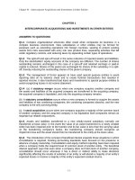
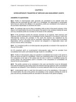
14–3. Determine the strain energy in the stepped
rod assembly. Portion AB is steel and BC is
brass. Ebr = 101 GPa, Est = 200 GPa, (sY)br = 410 MPa,
(sY)st = 250 MPa.
100 mm
A
B
30 kN
30 kN
1.5 m
Referring to the FBDs of cut segments in Fig. a and b,
+ ©F = 0;
:
x
NBC - 20 = 0
+ ©F = 0;
:
x
NAB - 30 - 30 - 20 = 0
NBC = 20 kN
NAB = 80 kN
p
The cross-sectional area of segments AB and BC are AAB = (0.12) = 2.5(10 - 3)p m2 and
4
p
ABC = (0.0752) = 1.40625(10 - 3)p m2.
4
(Ui)a = ©
NAB 2LAB
NBC 2LBC
N2L
=
+
2AE
2AAB Est
2ABC Ebr
=
C 80(103) D 2 (1.5)
2 C 2.5(10 - 3)p D C 200(109) D
+
C 20(103) D 2(0.5)
2 C 1.40625(10 - 3) p D C 101(109) D
= 3.28 J
Ans.
This result is valid only if s 6 sy.
sAB =
80(103)
NAB
= 10.19(106)Pa = 10.19 MPa 6 (sy)st = 250 MPa
=
AAB
2.5(10 - 3)p
O.K.
sBC =
20 (103)
NBC
= 4.527(106)Pa = 4.527 MPa 6 (sy)br = 410 MPa
=
ABC
1.40625(10 - 3) p
O.K.
1161
0.5 m
75 mm
C 20 kN
14 Solutions 46060_Part1
6/11/10
8:18 AM
Page 1162
© 2010 Pearson Education, Inc., Upper Saddle River, NJ. All rights reserved. This material is protected under all copyright laws as they currently
exist. No portion of this material may be reproduced, in any form or by any means, without permission in writing from the publisher.
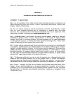
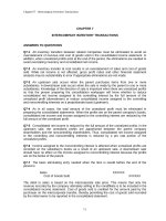
*14–4. Determine the torsional strain energy in the A-36
steel shaft. The shaft has a diameter of 40 mm.
900 Nиm
200 Nиm
0.5 m
Referring to the FBDs of the cut segments shown in Fig. a, b and c,
300 Nиm
0.5 m
TAB = 300 N # m
©Mx = 0;
TAB - 300 = 0
©Mx = 0;
TBC - 200 - 300 = 0
©Mx = 0;
TCD - 200 - 300 + 900 = 0 TCD = -400 N # m
0.5 m
TBC = 500 N # m
The shaft has a constant circular cross-section and its polar moment of inertia is
p
J = (0.024) = 80(10 - 9)p m4.
2
(Ui)t = ©
TAB 2 LAB
TBC 2LBC
TCD LCD
T2L
=
+
+
2GJ
2GJ
2GJ
2GJ
1
=
2 C 75(10 ) 80 (10 - 9)p D
9
c3002 (0.5) + 5002 (0.5) + (-400)2 (0.5) d
= 6.63 J
Ans.
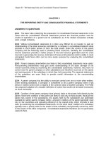
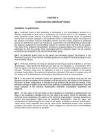
•14–5.
Determine the strain energy in the rod assembly.
Portion AB is steel, BC is brass, and CD is aluminum.
Est = 200 GPa, Ebr = 101 GPa, and Eal = 73.1 GPa.
15 mm
A
20 mm
2 kN B
25 mm
D
5 kN C
2 kN
5 kN
3 kN
300 mm
N2 L
Ui = ©
2AE
[3 (103) ]2 (0.3)
=
2 (p4 )(0.0152)(200)(109)
[7 (103) ]2 (0.4)
+
2(p4 )(0.022)(101)(109)
[-3 (103) ]2 (0.2)
+
2
(p4 )(0.0252)(73.1)(109)
= 0.372 N # m = 0.372 J
Ans.
1162
400 mm
200 mm
14 Solutions 46060_Part1
6/11/10
8:18 AM
Page 1163
© 2010 Pearson Education, Inc., Upper Saddle River, NJ. All rights reserved. This material is protected under all copyright laws as they currently
exist. No portion of this material may be reproduced, in any form or by any means, without permission in writing from the publisher.
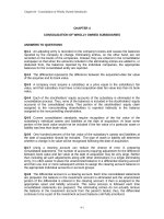
14–6. If P = 60 kN, determine the total strain energy
stored in the truss. Each member has a cross-sectional area
of 2.511032 mm2 and is made of A-36 steel.
2m
B
C
Normal Forces. The normal force developed in each member of the truss can be
determined using the method of joints.
1.5 m
Joint A (Fig. a)
D
+ ©F = 0;
:
x
FAD = 0
+ c ©Fy = 0;
FAB - 60 = 0
FAB = 60 kN (T)
P
Joint B (Fig. b)
+ c ©Fy = 0;
3
FBD a b - 60 = 0
5
FBD = 100 kN (C)
+ ©F = 0;
:
x
4
100 a b - FBC = 0
5
FBC = 80 kN (T)
Axial
Strain
Energy.
LBD = 222 + 1.52 = 2.5 m
(Ui)a = ©
=
A = 2.5 A 103 B mm2 = 2.5 A 10 - 3 B m2
and
N2L
2AE
2 C 2.5 A 10
1
-3
B D C 200 A 109 B D
c C 60 A 103 B D 2 (1.5) + C 100 A 103 B D 2 (2.5)
+ C 80 A 103 B D 2 (2) d
= 43.2 J
Ans.
This result is only valid if s 6 sY. We only need to check member BD since it is
subjected to the greatest normal force
sBD =
A
100 A 103 B
FBD
=
= 40 MPa 6 sY = 250 MPa
A
2.5 A 10 - 3 B
O.K.
1163
14 Solutions 46060_Part1
6/11/10
8:18 AM
Page 1164
© 2010 Pearson Education, Inc., Upper Saddle River, NJ. All rights reserved. This material is protected under all copyright laws as they currently
exist. No portion of this material may be reproduced, in any form or by any means, without permission in writing from the publisher.
14–7. Determine the maximum force P and the
corresponding maximum total strain energy stored in the
truss without causing any of the members to have
permanent deformation. Each member has the crosssectional area of 2.511032 mm2 and is made of A-36 steel.
2m
B
C
1.5 m
D
Normal Forces. The normal force developed in each member of the truss can be
determined using the method of joints.
Joint A (Fig. a)
+ ©F = 0;
:
x
FAD = 0
+ c ©Fy = 0;
FAB - P = 0
FAB = P (T)
Joint B (Fig. b)
+ c ©Fy = 0;
3
FBD a b - P = 0
5
+ ©F = 0;
:
x
4
1.6667Pa b - FBC = 0
5
FBD = 1.6667P (C)
FBC = 1.3333P(T)
Axial Strain Energy. A = 2.5 A 103 B mm2 = 2.5 A 10 - 3 B m2. Member BD is critical
since it is subjected to the greatest force. Thus,
sY =
FBD
A
250 A 106 B =
1.6667P
2.5 A 10 - 3 B
P = 375 kN
Ans.
Using the result of P
FAB = 375 kN
FBD = 625 kN
FBC = 500 kN
Here, LBD = 21.52 + 22 = 2.5 m.
(Ui)a = ©
N2L
=
2AE
1
=
2 C 2.5 A 10 - 3 B D C 200 A 109 B D
c C 375 A 103 B D 2 (1.5) + C 625 A 103 B D 2 (2.5) + C 500 A 103 B D 2 (2) d
= 1687.5 J = 1.6875 kJ
Ans.
1164
A
P
14 Solutions 46060_Part1
6/11/10
8:18 AM
Page 1165
© 2010 Pearson Education, Inc., Upper Saddle River, NJ. All rights reserved. This material is protected under all copyright laws as they currently
exist. No portion of this material may be reproduced, in any form or by any means, without permission in writing from the publisher.
*14–8. Determine the torsional strain energy in the A-36
steel shaft. The shaft has a radius of 30 mm.
4 kNиm
3 kNиm
0.5 m
T2L
1
=
[02(0.5) + ((3)(103))2(0.5) + ((1)(103))2(0.5)]
Ui = ©
2JG
2JG
=
0.5 m
2.5(106)
JG
2.5(106)
=
0.5 m
75(109)(p2 )(0.03)4
= 26.2 N # m = 26.2 J
Ans.
•14–9.
Determine the torsional strain energy in the A-36
steel shaft. The shaft has a radius of 40 mm.
12 kNиm
6 kNиm
0.5 m
Internal Torsional Moment: As shown on FBD.
8 kNиm
Torsional
Strain
Energy:
With
polar
moment
p
J =
A 0.044 B = 1.28 A 10 - 6 B p m4. Applying Eq. 14–22 gives
2
of
inertia
T2L
Ui = a
2GJ
=
1
C 80002 (0.6) + 20002 (0.4) +
2GJ
=
45.0(106) N2 # m3
GJ
A -100002 B (0.5) D
45.0(106)
=
9
75(10 )[1.28(10 - 6) p]
= 149 J
Ans.
1165
0.4 m
0.6 m
14 Solutions 46060_Part1
6/11/10
8:18 AM
Page 1166
© 2010 Pearson Education, Inc., Upper Saddle River, NJ. All rights reserved. This material is protected under all copyright laws as they currently
exist. No portion of this material may be reproduced, in any form or by any means, without permission in writing from the publisher.
14–10. Determine the torsional strain energy stored in the
tapered rod when it is subjected to the torque T. The rod is
made of material having a modulus of rigidity of G.
L
2r0
Internal Torque. The internal torque in the shaft is constant throughout its length as
shown in the free-body diagram of its cut segment, Fig. a,
Torsional Strain Energy. Referring to the geometry shown in Fig. b,
r = r0 +
T
r0
r0
(x) =
(L + x)
L
L
The polar moment of inertia of the bar in terms of x is
J(x) =
4
pr0 4
p 4
p r0
(L + x)4
r =
c (L + x) d =
2
2 L
2L4
We obtain,
L
(Ui)t =
T2dx
dx =
L0 2GJ
L0
L
T2 dx
2G B
pr0 4
2L4
(L + x)4 R
L
=
T2L4
dx
pr0 4G L0 (L + x)4
=
L
T2L4
1
B
R
`
pr0 4G
3(L + x)3 0
=
7 T2L
24pr0 4 G
Ans.
1166
r0
14 Solutions 46060_Part1
6/11/10
8:18 AM
Page 1167
© 2010 Pearson Education, Inc., Upper Saddle River, NJ. All rights reserved. This material is protected under all copyright laws as they currently
exist. No portion of this material may be reproduced, in any form or by any means, without permission in writing from the publisher.
14–11. The shaft assembly is fixed at C. The hollow
segment BC has an inner radius of 20 mm and outer radius
of 40 mm, while the solid segment AB has a radius of
20 mm. Determine the torsional strain energy stored in the
shaft. The shaft is made of 2014-T6 aluminum alloy. The
coupling at B is rigid.
600 mm
20 mm
600 mm
C
40 mm
B
60 Nиm
Internal Torque. Referring to the free-body diagram of segment AB, Fig. a,
TAB = -30 N # m
©Mx = 0; TAB + 30 = 0
Referring to the free-body diagram of segment BC, Fig. b,
©Mx = 0; TBC + 30 + 60 = 0
TAB = -90 N # m
p
Torsional Strain Energy. Here, JAB = A 0.024 B = 80 A 10 - 9 B p m4
2
p
JBC = A 0.044 - 0.024 B = 1200 A 10 - 9 B p m4,
2
(Ui)t = ©
TAB 2LAB
TBC 2LBC
T2L
=
+
2GJ
2GJAB
2GJBC
(-30)2(0.6)
=
and
2 C 27 A 109 B D C 80 A 10 - 9 B p D
(-90)2(0.6)
+
2 C 27 A 109 B D C 1200 A 10 - 9 B p D
= 0.06379 J
Ans.
1167
A
20 mm
30 Nиm
14 Solutions 46060_Part1
6/11/10
8:18 AM
Page 1168
© 2010 Pearson Education, Inc., Upper Saddle River, NJ. All rights reserved. This material is protected under all copyright laws as they currently
exist. No portion of this material may be reproduced, in any form or by any means, without permission in writing from the publisher.
*14–12. Consider the thin-walled tube of Fig. 5–28. Use
the formula for shear stress, tavg = T>2tAm, Eq. 5–18, and
the general equation of shear strain energy, Eq. 14–11, to
show that the twist of the tube is given by Eq. 5–20,
Hint: Equate the work done by the torque T to the strain
energy in the tube, determined from integrating the strain
energy for a differential element, Fig. 14–4, over the volume
of material.
Ui =
t2 dV
Lv 2 G
but t =
T
2 t Am
Thus,
Ui =
T2
dV
2
2
Lv 8 t AmG
L
=
2
T2
dV
T2
dA
TL
dA
=
dx =
2
2
2
2
2
2
8 A m G Lv t
8 A m G LA t L0
8 A mG LA t
However, dA = t ds. Thus,
Ui =
ds
T2L
2
8 AmG L t
Ue =
1
Tf
2
Ue = Ui
ds
T2L
1
Tf =
2
8 A2mG L t
f =
ds
TL
4 A2mG L t
QED
1168
14 Solutions 46060_Part1
6/11/10
8:18 AM
Page 1169
© 2010 Pearson Education, Inc., Upper Saddle River, NJ. All rights reserved. This material is protected under all copyright laws as they currently
exist. No portion of this material may be reproduced, in any form or by any means, without permission in writing from the publisher.
•14–13.
Determine the ratio of shearing strain energy to
bending strain energy for the rectangular cantilever beam
when it is subjected to the loading shown. The beam is made
of material having a modulus of elasticity of E and Poisson’s
ratio of n.
P
L
a
a
b
h
Section a – a
Internal Moment. Referring to the free-body diagram of the left beam’s cut
segment, Fig. a,
+ c ©Fy = 0;
-V - P = 0
V = -P
+ ©MO = 0;
M + Px = 0
M = -Px
Shearing Strain Energy. For the rectangular cross section, the form factor is fs =
6
5
6
2
2
L (-P) dx
L
fsV dx
5
3P2
3P2L
(Ui)v =
=
=
dx =
2GA
2G(bh)
5bhG L0
5bhG
L0
L0
L
However, G =
E
, then
2(1 + v)
(Ui)v =
6(1 + v)P2L
5bhE
Bending Strain Energy.
L
(Ui)b =
M2dx
=
L0 2EI
L0
L
(-Px)2dx2
2Ea
1
bh3 b
12
6P2
6P2 x3 L
2P2L3
2
x
dx
=
=
¢
≤
`
bh3E L0
bh3E 3 0
bh3E
L
=
Then, the ratio is
6(1 + v)P2L
3(1 + v) h 2
(Ui)v
5bhE
a b
=
=
2
3
(Ui)b
5
L
2P L
bh3E
Ans.
From this result, we can conclude that the proportion of the shearing strain energy
stored in the beam increases if the depth h of the beam’s cross section increases but
(Ui)v
1
= 0.009. the
decreases if L increases. Suppose that v = and L = 10h, then
2
(Ui)b
shearing strain energy is only 0.09% of the bending strain energy. Therefore, the
effect of the shearing strain energy is usually neglected if L 7 10h.
1169
14 Solutions 46060_Part1
6/11/10
8:18 AM
Page 1170
© 2010 Pearson Education, Inc., Upper Saddle River, NJ. All rights reserved. This material is protected under all copyright laws as they currently
exist. No portion of this material may be reproduced, in any form or by any means, without permission in writing from the publisher.
14–14. Determine the bending strain-energy in the beam
due to the loading shown. EI is constant.
M0
A
L
Ui =
L0
C
B
2
M dx
2EI
=
1
c
2EI L0
=
M20L
24EI
L>2
L
—
2
a
L
—
2
L>2
2
2
-M0
M0
x1 b dx1 +
a
x2 b dx2]
L
L
L0
Ans.
Note: Strain energy is always positive regardless of the sign of the moment function.
14–15. Determine the bending strain energy in the beam.
EI is constant.
P
P
Referring to the FBD of the entire beam, Fig. a,
a + ©MB = 0;
Pa
L
3L
b + Pa
b - Ay (L) = 0
4
4
L
4
Ay = P
Using the coordinates, x1 and x2, the FBDs of the beam’s cut segments in Figs. b and
c are drawn. For coordinate x1,
a + ©Mc = 0;
M(x1) - Px1 = 0
M(x1) = Px1
For coordinate x2 coordinate,
a + ©Mc = 0;
M(x2) - Pa
L
b = 0
4
L
(Ui)b = ©
1
M2dx
=
c2
2EI
2EI
L0
L0
M(x2) =
PL
4
L>4
L>2
(Px1)2dx1 +
L0
a
=
P2 3
P2L2 2
1
c2 a
x1 b ` +
x ` d
2EI
3
16 2 0
0
=
P2L3
48EI
L
4
PL 2
b dx2 d
4
L
Ans.
1170
L
2
L
4
14 Solutions 46060_Part1
6/11/10
8:18 AM
Page 1171
© 2010 Pearson Education, Inc., Upper Saddle River, NJ. All rights reserved. This material is protected under all copyright laws as they currently
exist. No portion of this material may be reproduced, in any form or by any means, without permission in writing from the publisher.
*14–16. Determine the bending strain energy in the A-36
structural steel W10 * 12 beam. Obtain the answer using
the coordinates 1a2 x1 and x4, and 1b2 x2 and x3.
6 kip
x1
x4
x2
12 ft
Support Reactions: As shown on FBD(a).
Internal Moment Function: As shown on FBD(b), (c), (d) and (e).
Bending Strain Energy:
Using coordinates x1 and x4 and applying Eq. 14–17 gives
L
Ui =
M2dx
L0 2EI
1
c
2EI L0
12ft
=
6ft
1
c
2EI L0
12ft
=
=
3888 kip2 # ft3
EI
(-3.00x1)2 dx1 +
L0
(-6.00x4)2 dx4 d
6ft
9.00x21dx1 +
L0
36.0x24 dx4 d
For W10 * 12 wide flange section, I = 53.8 in4.
Ui =
3888(123)
29.0(103)(53.8)
= 4.306 in # kip = 359 ft # lb
Ans.
b) Using coordinates x2 and x3 and applying Eq. 14–17 gives
L
Ui =
M2dx
L0 2EI
1
c
2EI L0
12ft
=
6ft
1
c
2EI L0
12ft
=
=
3888 kip2 # ft3
EI
(3.00x2 - 36.0)2dx2 +
L0
(6.00x3 - 36.0)2 dx3 d
A 9.00x22 - 216x + 1296 B dx2 +
6ft
L0
A 36.0x23 - 432x + 1296 B dx3 d
For W 10 * 12 wide flange section, I = 53.8 in4.
Ui =
3888(123)
29.0(103)(53.8)
= 4.306 in # kip = 359 ft # lb
Ans.
1171
x3
6 ft
14 Solutions 46060_Part1
6/11/10
8:18 AM
Page 1172
© 2010 Pearson Education, Inc., Upper Saddle River, NJ. All rights reserved. This material is protected under all copyright laws as they currently
exist. No portion of this material may be reproduced, in any form or by any means, without permission in writing from the publisher.
•14–17.
Determine the bending strain energy in the A-36
steel beam. I = 99.2 (106) mm4.
9 kN/m
6m
Referring to the FBD of the entire beam, Fig. a,
1
(9)(6)(2) - Ay (6) = 0
2
a + ©MB = 0;
Ay = 9 kN
Referring to the FBD of the beam’s left cut segment, Fig. b,
a + ©M0 = 0;
M(x) +
1 3
a xb (x) (x>3) - 9x = 0
2 2
M(x) = a 9x L
(Ui)b =
For
A
36
1 3
x b
4
kN # m
M2 dx
1
=
2EI L0
L0 2EI
6m
a 9x -
1
2EI L0
6m
=
a 81x2 +
=
1 7
9 5 2 6m
1
c a27x3 +
x x b
d
2EI
112
10
0
=
666.51 kN2 # m3
EI
steel,
E = 200 GPa.
Here,
= 99.2(10 - 6) m4. Then
(Ui)b =
666.51 (10002)
200(109) C 99.2(10 - 6) D
1 3 2
x b dx
4
1 6
9
x - x4 bdx
16
2
I = C 99.2 (106) mm4 D a
4
1m
b
1000 mm
Ans.
= 33.6 J
1172
14 Solutions 46060_Part1
6/11/10
8:18 AM
Page 1173
© 2010 Pearson Education, Inc., Upper Saddle River, NJ. All rights reserved. This material is protected under all copyright laws as they currently
exist. No portion of this material may be reproduced, in any form or by any means, without permission in writing from the publisher.
14–18. Determine the bending strain energy in the A-36
steel beam due to the distributed load. I = 122 (106) mm4.
15 kN/m
A
B
3m
Referring to the FBD of the entire beam, Fig. a,
1
(15)(3) = 0
2
Ay -
+ c ©Fy = 0;
a + ©MA = 0;
MA -
Ay = 22.5 kN
1
(15)(3)(2) = 0
2
MA = 45 kN # m
Referring to the FBD of the beam’s left cut segment, Fig. b,
a + ©M0 = 0;
M(x) +
1
(5x)(x)(x>3) - 22.5x + 45 = 0
2
M(x) = (22.5x - 0.8333x3 - 45) kN # m
L
(Ui)b =
=
1
M2dx
=
c
2EI
2EI
L0
L0
1
c
2EI L0
3m
(22.5x - 0.8333x3 - 45)2 dx
3m
0.6944x6 - 37.5x4 + 75x3 + 506.25x2
- 2025x + 2025)dx d
=
1
a0.09921x7 - 7.5x5 + 18.75x4 + 168.75x3
2EI
- 1012.5x2 + 2025xb 2
3m
0
715.98 kN2 # m2
=
EI
For
A
36
steel,
E = 200 GPa.
Here,
I = c122(106) mm4 d a
4
1m
b
1000 mm
= 122(10 - 6) m4. Thus,
(Ui)b =
715.98 (10002)
200(109) C 122 (10 - 6) D
Ans.
= 29.3 J
1173
14 Solutions 46060_Part1
6/11/10
8:18 AM
Page 1174
© 2010 Pearson Education, Inc., Upper Saddle River, NJ. All rights reserved. This material is protected under all copyright laws as they currently
exist. No portion of this material may be reproduced, in any form or by any means, without permission in writing from the publisher.
14–19. Determine the strain energy in the horizontal
curved bar due to torsion. There is a vertical force P acting
at its end. JG is constant.
r
90Њ
P
T = Pr(1 - cos u)
Strain energy:
L
Ui =
T2 ds
L0 2JG
However,
ds = rdu
s = ru;
u
Ui =
T2rdu
r
=
2JG L0
L0 2JG
P2r3
2JG L0
p>2
=
P2r3
2JG L0
p>2
=
P2r3
2JG L0
p>2
=
=
P2r3 3p
a
- 1b
JG
8
p>2
[Pr(1 - cos u)]2du
(1 - cos u)2 du
(1 + cos2 u - 2 cos u)du
(1 +
cos 2u + 1
- 2 cos u) du
2
Ans.
1174
14 Solutions 46060_Part1
6/11/10
8:18 AM
Page 1175
© 2010 Pearson Education, Inc., Upper Saddle River, NJ. All rights reserved. This material is protected under all copyright laws as they currently
exist. No portion of this material may be reproduced, in any form or by any means, without permission in writing from the publisher.
*14–20. Determine the bending strain energy in the beam
and the axial strain energy in each of the two rods. The
beam is made of 2014-T6 aluminum and has a square cross
section 50 mm by 50 mm. The rods are made of A-36 steel
and have a circular cross section with a 20-mm diameter.
2m
8 kN
Support Reactions: As shown on FBD(a).
8 kN
Internal Moment Function: As shown on FBD(b) and (c).
Axial Strain Energy: Applying Eq. 14–16 gives
1m
N2L
(Ui)a =
2AE
C 8.00(103) D 2 (2)
=
2AE
64.0(106) N2 # m
AE
=
64.0(106)
=
p
4
(0.022) [200(109)]
Ans.
= 1.02 J
Bending Strain Energy: Applying Eq. 14–17 gives
L
(Ui) b =
M2dx
L0 2EI
=
1
B2
2EI
L0
=
85.333 kN2 # m3
EI
1m
(8.00x1)2 dx 1 +
2m
L0
8.002 dx2 R
85.333(106)
=
1
73.1(109) C 12
(0.05) (0.053) D
= 2241.3 N # m = 2.24 kJ
Ans.
1175
2m
1m
14 Solutions 46060_Part1
6/11/10
8:18 AM
Page 1176
© 2010 Pearson Education, Inc., Upper Saddle River, NJ. All rights reserved. This material is protected under all copyright laws as they currently
exist. No portion of this material may be reproduced, in any form or by any means, without permission in writing from the publisher.
•14–21.
The pipe lies in the horizontal plane. If it is
subjected to a vertical force P at its end, determine the
strain energy due to bending and torsion. Express the
results in terms of the cross-sectional properties I and J, and
the material properties E and G.
z
L
C
x
B
L
—
2
A
P
Ui =
M2 dx
T2 dx
+
L 2E I
L 2JG
L
2
=
L
L PL 2
( 2 ) dx
(P x)2 dx
(P x)2 dx
+
+
2
E
I
2
EI
L0
L0 2 J G
L0
=
L 31
P2 L3
P2L2
P2
a b
+
+
(L)
2EI 2 3
2EI 3
8JG
=
P2 L3
3 P2 L3
+
16 E I
8JG
= P2 L3 c
3
1
+
d
16 E I
8JG
Ans.
1176
y
14 Solutions 46060_Part1
6/11/10
8:18 AM
Page 1177
© 2010 Pearson Education, Inc., Upper Saddle River, NJ. All rights reserved. This material is protected under all copyright laws as they currently
exist. No portion of this material may be reproduced, in any form or by any means, without permission in writing from the publisher.
14–22. The beam shown is tapered along its width. If a
force P is applied to its end, determine the strain energy in
the beam and compare this result with that of a beam that
has a constant rectangular cross section of width b and
height h.
b
h
P
L
Moment of Inertia: For the beam with the uniform section,
I =
bh3
= I0
12
For the beam with the tapered section,
I =
I0
bh3
1 b
a xb A h3 B =
x =
x
12 L
12L
L
Internal Moment Function: As shown on FBD.
Bending Strain Energy: For the beam with the tapered section, applying Eq. 14–17 gives
L
UI =
M2 dx
L0 2EI
=
L
(-Px)2
1
dx
I0
2E L0
L x
=
P2L
xdx
2EI0 L0
=
P2L3
3P2 L3
=
4EI0
bh3 E
L
Ans.
For the beam with the uniform section,
L
Ui =
M2dx
L0 2EI
L
=
1
(-Px)2 dx
2EI0 L0
=
P3 L3
6EI0
The strain energy in the capered beam is 1.5 times as great as that in the beam
having a uniform cross section.
Ans.
1177
14 Solutions 46060_Part1
6/11/10
8:18 AM
Page 1178
© 2010 Pearson Education, Inc., Upper Saddle River, NJ. All rights reserved. This material is protected under all copyright laws as they currently
exist. No portion of this material may be reproduced, in any form or by any means, without permission in writing from the publisher.
14–23. Determine the bending strain energy in the
cantilevered beam due to a uniform load w. Solve the
problem two ways. (a) Apply Eq. 14–17. (b) The load w dx
acting on a segment dx of the beam is displaced a distance y,
where y = w1-x4 + 4L3x - 3L42>124EI2, the equation of
the elastic curve. Hence the internal strain energy in the
differential segment dx of the beam is equal to the external
work, i.e., dUi = 121w dx21-y2. Integrate this equation to
obtain the total strain energy in the beam. EI is constant.
w dx
w
dx
Internal Moment Function: As shown on FBD.
Bending Strain Energy: a) Applying Eq. 14–17 gives
L
Ui =
M2dx
L0 2EI
L
=
1
w 2
c - x2 d dx R
B
2EI L0
2
=
w2
x4 dx R
B
8EI L0
=
w2 L5
40EI
L
b) Integrating dUi =
1
w
(wdx) B A -x4 + 4L3x - 3L4 B R
2
24EI
dUi =
w2
A x4 -4L3x + 3L4 B dx
48EI
Ui =
=
Ans.
1
(wdx)( -y)
2
dUi =
w2
48EI L0
L
x
L
A x4 - 4L3x + 3L4 B dx
w2L5
40EI
Ans.
1178
14 Solutions 46060_Part1
6/11/10
8:18 AM
Page 1179
© 2010 Pearson Education, Inc., Upper Saddle River, NJ. All rights reserved. This material is protected under all copyright laws as they currently
exist. No portion of this material may be reproduced, in any form or by any means, without permission in writing from the publisher.
*14–24. Determine the bending strain energy in the
simply supported beam due to a uniform load w. Solve the
problem two ways. (a) Apply Eq. 14–17. (b) The load w dx
acting on the segment dx of the beam is displaced a distance
y, where y = w1-x4 + 2Lx3 - L3x2>124EI2, the equation
of the elastic curve. Hence the internal strain energy in the
differential segment dx of the beam is equal to the external
work, i.e., dUi = 121w dx21-y2. Integrate this equation to
obtain the total strain energy in the beam. EI is constant.
w dx
w
x
Support Reactions: As shown on FBD(a).
Internal Moment Function: As shown on FBD(b).
Bending Strain Energy: a) Applying Eq. 14–17 gives
L
Ui =
M2dx
L0 2EI
L
=
2
1
w
2
c (Lx - x ) d dx R
B
2EI L0 2
=
w2
(L2x2 + x4 - 2Lx3) dx R
B
8EI L0
=
w2L5
240EI
L
b) Integrating dUi =
Ans.
1
(wdx) (-y)
2
dUi =
1
w
(wdx) B (-x4 + 2Lx3 - L3x) R
2
24EI
dUi =
w2
(x4 - 2Lx3 + L3x) dx
48EI
L
Ui =
=
w2
(x4 - 2Lx3 + L3x) dx
48EI L0
w2L5
240EI
Ans.
1179
dx
L
14 Solutions 46060_Part1
6/11/10
8:18 AM
Page 1180
© 2010 Pearson Education, Inc., Upper Saddle River, NJ. All rights reserved. This material is protected under all copyright laws as they currently
exist. No portion of this material may be reproduced, in any form or by any means, without permission in writing from the publisher.
•14–25. Determine the horizontal displacement of joint A.
Each bar is made of A-36 steel and has a cross-sectional
area of 1.5 in2.
2 kip
A
3 ft
D
3 ft
C
B
4 ft
Member Forces: Applying the method of joints to joint at A, we have
+ ©F = 0;
:
x
4
- 2 = 0
F
5 AD
+ c ©Fy = 0;
FAB -
FAD = 2.50 kip (T)
3
(2.50) = 0
5
FAB = 1.50 kip (C)
At joint D
+ ©F = 0;
:
x
4
4
F
- (2.50) = 0
5 DB
5
+ c ©Fy = 0;
3
3
( 2.50) + (2.50) - FDC = 0
5
5
FDB = 2.50 kip (C)
FDC = 3.00 kip (T)
Axial Strain Energy: Applying Eq. 14–16, we have
N2L
Ui = a
2AE
=
1
[2.502 (5) + (-1.50)2 (6) + (-2.50)2 (5) + 3.002(3)]
2AE
=
51.5 kip2 # ft
AE
51.5(12)
=
1.5[29.0(103)]
= 0.014207 in # kip
External Work: The external work done by 2 kip force is
Ue =
1
(2) (¢ A)h = (¢ A)h
2
Conservation of Energy:
Ue = Ui
(¢ A)h = 0.014207
= 0.0142 in.
Ans.
1180
14 Solutions 46060_Part1
6/11/10
8:18 AM
Page 1181
© 2010 Pearson Education, Inc., Upper Saddle River, NJ. All rights reserved. This material is protected under all copyright laws as they currently
exist. No portion of this material may be reproduced, in any form or by any means, without permission in writing from the publisher.
14–26. Determine the horizontal displacement of joint C.
AE is constant.
C
P
L
L
A
B
L
Member Forces: Applying the method of joints to C, we have
+ c ©Fy = 0;
FBC cos 30° - FAC cos 30° = 0
+ ©F = 0;
:
x
P - 2F sin 30° = 0
Hence,
FBC = P (C)
FBC = FAC = F
F = P
FAC = P (T)
Axial Strain Energy: Applying Eq. 14–16, we have
N2L
Ui = a
2AE
=
1
C P2L + (-P)2 L D
2AE
=
P2L
AE
External Work: The external work done by force P is
Ui =
1
P(¢ c)k
2
Conservation of Energy:
Ue = Ui
P2L
1
P(¢ C)k =
2
AE
(¢ C)k =
2PL
AE
Ans.
1181
14 Solutions 46060_Part1
6/11/10
8:18 AM
Page 1182
© 2010 Pearson Education, Inc., Upper Saddle River, NJ. All rights reserved. This material is protected under all copyright laws as they currently
exist. No portion of this material may be reproduced, in any form or by any means, without permission in writing from the publisher.
14–27. Determine the vertical displacement of joint C. AE
is constant.
A
L
L
C
L
B
Joint C:
+ ©F = 0
:
x
FCB cos 30° - FCA cos 30° = 0
FCB = FCA
+ c © Fy = 0
FCA sin 30° + FCB sin 30° - P = 0
FCB = FCA = P
Conservation of energy:
Ue = Ui
N2L
1
P¢ C = ©
2
2EA
L
1
2
P¢ C =
[F 2 + FCA
]
2
2EA CB
P¢ C =
¢C =
L
(P2 + P2)
EA
2PL
AE
Ans.
1182
P
14 Solutions 46060_Part1
6/11/10
8:18 AM
Page 1183
© 2010 Pearson Education, Inc., Upper Saddle River, NJ. All rights reserved. This material is protected under all copyright laws as they currently
exist. No portion of this material may be reproduced, in any form or by any means, without permission in writing from the publisher.
*14–28. Determine the horizontal displacement of joint D.
AE is constant.
D
C
P
Joint B:
L
+ c ©Fy = 0;
FBC = 0.75P
+ ©F = 0;
;
x
FBA = P
0.6 L
B
A
Joint D:
0.8 L
+ T ©Fy = 0;
FDA = 0
+ ©Fx = 0;
:
FDC = P
Joint A:
+ T ©Fy = 0;
3
F
- 0.75P = 0
5 AC
FAC = 1.25P
Conservation of energy:
Ue = Ui
N2L
1
P¢ D = ©
2
2AE
1
1
P¢ D =
[(0.75P)2(0.6L) + (P)2(0.8L) + (02)(0.6L)
2
2AE
+ (P2)(0.8L) + (1.25P)2(L)]
¢D =
3.50PL
AE
Ans.
•14–29.
The cantilevered beam is subjected to a couple
moment M0 applied at its end. Determine the slope of the
beam at B. EI is constant.
M0
A
B
Ui =
2
L
M20L
M dx
1
=
M20 dx =
2EI L0
2EI
L0 2EI
Ue =
1
(M0 uB)
2
L
L
Conservation of energy:
Ue = Ui
M0 2L
1
M0 uB =
2
2EI
uB =
M0L
EI
Ans.
1183