KIA TRAINING communication tài liệu đào tạo mạng giao tiếp CAN pps
Bạn đang xem bản rút gọn của tài liệu. Xem và tải ngay bản đầy đủ của tài liệu tại đây (1.84 MB, 30 trang )
Hi-Scan Pro Utilization
Hi-Scan Pro Utilization
(EMS Diagnosis Manual)
Hi-Scan Pro Utilization
Contents
1. Crankshaft Position Sensor Signal Analysis
2. Camshaft Position Sensor Signal Analysis
3. TPS Signal Analysis
4. Air Flow Sensor Signal Analysis
5. O2 Sensor Signal Analysis
6. Injector Signal Analysis
7. ISC Valve Signal Analysis
8. Air Temp. Sensor Signal Analysis
9. Knock Sensor Signal Analysis
10. Vehicle Speed Sensor Signal Analysis
11. EGR Valve Signal Analysis
12. Purge Valve Signal Analysis
13. O2 Sensor Heater Signal Analysis
Hi-Scan Pro Utilization
1. Crankshaft position sensor(CKP) signal
analysis
1.1 Introduction of Crankshaft position sensor and principle
(1/2)
About
Sensor
Crankshaft position sensor is a sensor for locating piston by ECM and necessary to find
ignition time .
If the signal of the Crankshaft position sensor keeps its consistency, then it is hard to find
starting and ending point. Therefore, two teeth are taken out from the crank and it is called
Long Tooth and the rest are called Short Tooth. By using long Tooth, TDC ( Top Dead
Center ) is found.
Contents shown by signal of crank sensor.
1. Ignition time = 360deg * Number of tooth before TDC / Number of tooth at
one revolution of engine.
Ignition time is calculated by number of tooth between the long tooth and
peak voltage. Peak voltage is obtained by measuring signal of Crankshaft
Position sensor and primary ignition wave simultaneously.
2. Engine speed (RPM) = 60 / ( Time between long tooth * Number of long tooth
at one revolution of engine)
RPM is calculated by number of long tooth at one revolution of engine.
Hi-Scan Pro Utilization
1. 2 Introduction of Crankshaft position sensor and
principle (2/2)
Sensor type
Three mostly used Crankshaft position sensor.
1. Optical Sensor : The sensor is used on a single-bodied cam shaft with a hole on the
disk. The signal is recognized when the signal passes through the hole while the disk is
revolving. This particular sensor is destructive by heat and humidity and makes lots of
noise. ( This is the only sensor that disk for Crankshaft position sensor revolve 1
revolution while crank shaft rotate 2 revolution. )
2. Magnetic Sensor : If the electromagnetic power generated by coil is intercepted by
revolution of a single-bodied camshaft with target wheel (normally outside of flywheel ),
then the voltage is generated. The sensor is using this voltage for signal..
3. Hall type sensor : The circuit is included in the sensor inside. This sensor electron
The circuit included inside the sensor discharge the electron. The single bodied crank
shaft with target wheel (normally outside of fly wheel ) disturbs discharging of electron
and generate the voltage. This voltage is used for signal.
Optical type
Algorithm
Magnetic type sensor
signal
This sensor is the most important sensor for the ECM. If sporadic engine stall
happened , then suspect this sensor at first.
1. If the ECM detects fault on this signal, then the ECM stop “fuel injection and ignition
2. If the ECM could not detect fault signal, then normal component or not equipped
component might be detected as a fault one.
Hi-Scan Pro Utilization
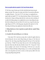
1.3 The Methodology of Crankshaft Position Sensor Signal
Measurement
How to connect sensor : A and B channel can
Hi-Scan Mode : Please perform
be used simultaneously. The plus of probe(Red
color) should be connected with signal line of
sensor and the minus(black color) should be
connected with ground line of sensor.
following procedure on the screen,
- Vehicle selection
System(Engine / Transmission /
ABS …)Crankshaft Position
Sensor Measuring
Sensor repair info
view.
Normal value
About sensor
Data analysis
Hi-Scan Pro Utilization
2. Camshaft Position sensor signal analysis
2.1 Introduction of Camshaft Position sensor and principle(1/2)
About Sensor
Camshaft Position sensor is a sensor that indicate the TDC of each cylinders by
the ECM. This sensor is necessary to calculating injection phase. We can
calculate the TDC from the Crankshaft Position sensor but cylinder number.
Therefore ECM recognize the TDC right after Camshaft Position signal. The ECM
use the cam signal located between two long tooth. If the signal of cam is located
inside the long tooth, then The ECM detects it as a fault.
TDC
TDC
19th
19th
TDC shown after CAM signal
is the first TDC.
Information from the signal of cam sensor : TDC of the1st
cylinder
Hi-Scan Pro Utilization
2.2 Introduction of Camshaft Position sensor and principle(2/2)
About Sensor
Three mostly used Camshaft Position sensor.
1. Optical Sensor : The sensor is used on a single-bodied cam shaft with a hole on the
disk. The signal is recognized when the signal passes through the hole while the disk is
revolving. This particular sensor is destructive by heat and humidity and makes lots of
noise. ( This is the only sensor that disk for Crankshaft Position sensor revolve 2
revolution while crank shaft rotate 1 revolution. )
2. Magnetic Sensor : If the electromagnetic power generated by coil is intercepted by
the revolution of a single-bodied camshaft with a target wheel (normally outside of the
flywheel ), then the voltage is generated. The sensor use this voltage for signal.
3. Hall type sensor : The circuit is included in the sensor. This sensor electron The
circuit discharge the electron. The single bodied crank shaft with a target wheel
(normally outside of fly wheel ) disturbs discharging of the electron and generates
the voltage. This voltage is used for signal
Optical / hall type sensor
signal
Algorithm
Magnetic type sensor
signal
In order to reduce the emission, injection should be finished before intake valve open.
If the fuel is injected on the hot intake valve, then fuel is well vaporized and this helps
good combustion.
Therefore, cam signal is used to identify the cylinder number.
In case of no spark time adjustment type,we can know it by comparing cam signal
position with Crankshaft Position sensor.
Hi-Scan Pro Utilization
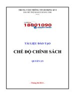
2.3 The Methodology of Camshaft Angle Sensor Signal
Measurement
How to connect sensor : Channels A and B
Hi-Scan Mode : Please perform
can be used simultaneously. The plus of
probe(Red color) should be connected to the
signal line of sensor and the minus(black color)
should be connected to the
ground line of the
sensor.
following procedure on the screen,
- Vehicle
selectionSystem(ENG)CAM
Part(F4 key) Measuring
Remark :
Since both A and B channels can be used
at the same time, it is better to measure
crank and Camshaft Position signal
simultaneously.
Sensor repair info view
Normal valve
About sensor
Data analysis
Hi-Scan Pro Utilization
3. Throttle Position Sensor (TPS) signal analysis
3.1 Introduction of TPS and principle
About Sensor
TPS is the sensor to find out how much the acceleration pedal accelerates. If the
line of this sensor is broken, then more than 4.7V or 2.1V of constant signal
voltage can be produced depending on ECM internal circuit..
Sensor type
Algorithm
Wiper type is the mostly used signal sensing type by now.
In order to response to the driver’s will quickly, fuel injection is controlled by the
acceleration speed and pedal value. If the pedal value is more than 50%, then the
oxygen sensor feedback control is stopped to control the engine with more torque.
In case of sensor failure, intake air sensor is substituted for TPS. Therefore, fast accel
and decel can not be detected with sensor failure and hesitation can occur.
Hi-Scan Pro Utilization
3.2 The Methodology of TPS Signal Measurement
How to connect sensor : Channels A and B
can be used simultaneously. The plus of
probe(Red color) should be connected to the
signal line of the sensor and the minus(black
color) should be connected to the ground line of
sensor.
Hi-Scan Mode : Please perform
following procedure on the screen,
- Vehicle
selectionSystem(ENG)TPS
Part(F4 key) Measuring
Remark :
As it is possible to use A,B channels
at the same time, it is better to
measure TPS and intake air flow
simultaneously.
Sensor repair info view
Normal value
About Sensor
Data analysis
Hi-Scan Pro Utilization
4. Intake Air Flow Sensor Signal Analysis
4.1 Introduction of Intake Air Flow Sensor and Algorithm
About
Sensor
Sensor
type
Algorith
m
This is the sensor to see how much air flow is coming into the cylinder. It is very
important to calculate injection time. If the line is broken, then there are occasions
when output voltage is over 4.7V depending on internal circuit like TPS.
Mostly used sensors by now are the MAP sensor ( Intake manifold pressure check ),
MAF (Mass Air Flow :the resistance is changed when heated tip is cooled by inducted
air )and Karman Vortex (This sensor monitors vortices generated as the intake air flows
past vortex generators. Air flow is calculated by the frequency of ultrasonic waves that
are changed depending on the amount of vortices. )
The fuel quantity is decided by the air flow and the injector opening time decides fuel
quantity. The calculated fuel amount is compensated more precisely by oxygen sensor
feedback compensation. In case of air flow sensor error, the substitute value is
calculated by engine speed and TPS.
Hi-Scan Pro Utilization
4.2 The Methodology of Air Flow Sensor Signal Measurement
How to connect sensor : A and B channel can
be used simultaneously. The plus of probe(Red
color) should be connected with signal line of
sensor and the minus(black color) should be
connected with ground line of sensor.
Hi-Scan Mode : Please perform
following procedure on the screen,
- Vehicle
selectionSystem(ENG)MAP
Part(F4 key) Measuring
Remark :
As it is possible to measure A,B
channels, it is better to measure intake
air flow and TPS simultaneously.
Sensor repair info view
Normal value
About sensor
Data analysis
Hi-Scan Pro Utilization
5 Oxygen sensor signal analysis
5.1 Introduction of oxygen sensor and principle
About Sensor
This is the sensor to compensate the fuel injection to get the stoichiometric air fuel
ratio (14.6). The different voltage is generated depending on fuel richness
( oxygen richness ). According to this voltage variation, fuel injection is added or
subtracted so that always relevant fuel is injected.
Sensor
type
Mostly used sensor now is the Zirconia ( It generate the voltage from 0V to 1V by
oxygen richness ), Titania ( It generate different resistance by oxygen richness ) and
UEGO sensor ( It is used for lean burn engine and it generate different current by
oxygen richness ). Titania and Zirconia sensors are classified with and without heater.
Algorith
m
Oxygen sensor produce below 0.5V with rich oxygen( lean fuel) and over 0.5V with lean
oxygen (rich fuel). Using this, ECM inject more fuel when oxygen sensor voltage is
below 0.5V and reduce fuel as soon as voltage is over 0.5V. By continuing this control,
supplied fuel is getting close to stoichiometirc air fuel ratio. This is the feedback control.
In case of sensor failure, fuel is supplied by basic calculation.
Hi-Scan Pro Utilization
5.2 The Methodology of O2 Sensor Signal Measurement
How to connect sensor : A and B channel can
Hi-Scan Mode : Please perform
be used simultaneously. The plus of probe(Red
color) should be connected with signal line of
sensor and the minus(black color) should be
connected with ground line of sensor.
following procedure on the screen,
- Vehicle
selectionSystem(ENG)O2 sensor
Part(F4 key) Measuring
Remark :
As it is possible to measure A,B
channels, it is better to measure TPS
too.
Sensor repair info view
Normal value
About
Data analysis
Hi-Scan Pro Utilization
6 Injector active signal analysis
6.1 Introduction of Injector and principle
About
Injector
The fuel quantity is decided by the air flow and the injector opening time decides fuel
quantity. The injector open by electromagnetic power and close by spring
force. Since the electromagnetic power is depending on battery power,
injector opening time is compensated by battery power.
Injector
type
The principles of opening ( open by electromagnetic power and close by spring force )
are mostly same. But it is classified into orifice and pintle type by injection hole.
Algorith
m
If the signal of Crankshaft Position sensor has the noise or broken signal, ECM stop the
fuel injection until it get normal signal of Crankshaft Position sensor.
Therefore, engine can be unstable or stall.
Hi-Scan Pro Utilization
6.2 The Methodology of Injector Signal Measurement
How to connect sensor : A and B channel can
be used simultaneously. The plus of probe(Red
color) should be connected with signal line of
sensor and the minus(black color) should be
connected with ground line of sensor.
Hi-Scan Mode : Please perform
following procedure on the screen,
- Scope meter Engine
Actuator Injection Measuring
.
Sensor repair info view
Normal value
About sensor
Data analysis
Hi-Scan Pro Utilization
7. ISC valve control signal analysis
7.1 Introduction of ISC valve and principle
About
ISC valve
ISC valve
type
ISC valve is the valve that bypass the air to keep constant engine speed when
throttle valve is closed. ECM control only the opening of the valve and air is
supplied by the under pressure in the surge tank..
Three mostly used type are DC type controlled by DC motor, Duty type controlled by
duty and Step type controlled by the electromagnet
ISC valve
ISC valve
Control line
Control line
Control line
Control line
Control line
GND Duty control
Control line
Duty type (2 coil)
Algorith
m
Step motor type
The ECM compare the engine speed with target speed and open or close the valve
when engine speed is lower or higher than target. This compensation is composed of
proportional, integral and differential term- so called PID control..
Engine speed
Engine speed
ISC valve opening
Target speed
Hi-Scan Pro Utilization
7.2 The Methodology of ISC Valve Signal Measurement
How to connect sensor : A and B channel can
Hi-Scan Mode : Please perform
be used simultaneously. The plus of probe(Red
color) should be connected with signal line of
sensor and the minus(black color) should be
connected with ground line of sensor.
following procedure on the screen,
- Scope meter Engine
Actuator ISC Measuring
Sensor repair info view
IAC
valve
Normal value
IAC
valve
About sensor
Data analysis
Hi-Scan Pro Utilization
8. Temperature sensor signal analysis
8.1 Introduction of temperature sensor signal and principle
About
Sensor
Sensor
Type
Coolant sensor is a sensor for detecting of how much engine is heated up and
necessary to control injection/ignition/ISC valve depending on engine temperature.
Because engine load is surely different depending on engine temperature.
Intake air temperature sensor is used to calculate exact intake air flow and
necessary for MAP sensor type. But it is often not to use it with MAF(Mass air flow
)type.
Some of MAP sensor include intake air temperature sensor inside and it is called
T-MAP sensor.
Mostly used type is a thermistor type that increase the resistance with high temperature
and decrease the resistance with low temperature.
.
T_MAP sensor
Intake air temp. sensor
Algorith
m
Coolant temp.
sensor
Intake air temperature sensor is a sensor for calculating intake air quantity more exactly.
The coolant temperature sensor is to set different target of fuel(Air Fuel ratio)/target
speed/spark time in accordance with coolant temperature to compensate different
engine
load area without feedback control depending on coolant temp
Target lambda
Target ignition area depending on coolant temp. - idle status
AF range
Spark range
Hi-Scan Pro Utilization
8.2 The Methodology of Temperature Sensor Signal
Measurement
How to connect sensor : A and B channel can
Hi-Scan Mode : Please perform
be used simultaneously. The plus of probe(Red
color) should be connected with signal line of
sensor and the minus(black color) should be
connected with ground line of sensor.
following procedure on the screen,
- Scope meter Engine
Sensor WTS Measuring
Sensor repair info view
Coolant sensor
Coolant sensor
Normal value
Coolant sensor
About sensor
Data analysis
Hi-Scan Pro Utilization
9. Knock sensor signal analysis
9.1 Introduction of knock sensor and algorithm
About
Sensor
Sensor type
The knock sensor employ the
piezoelectric element or silicon that
produce the signal(voltage) when it
gets pressure. If there is knocking in
the engine, then vibration is
transformed to pressure vibration and
it produces voltage. According to
this voltage, knocking is detected.
It is difficult to distinguish the knock sensor type by means of sensor shape.
element to detect vibration may be different.
But the
Knock sensor
Algorithm
The frequency of knocking signal is too fast(about 6 - 18Khz) to analyze it by ECM.
Therefore, this signal is
sampled by hardware
and knocking is
detected.
But the frequency of bad
engine vibration can be
overlapped with
frequency of knocking.
So, too much knocking
can be detected by
engine vibration.
Hi-Scan Pro Utilization
9.2 The Methodology of Knock Sensor Signal Measurement
How to connect sensor : A and B channel can
be used simultaneously. The plus of probe(Red
color) should be connected with signal line of
sensor and the minus(black color) should be
connected with ground line of sensor.
Hi-Scan Mode : Please perform
following procedure on the screen,
- Scope meter Engine
Sensor Knock Measuring
Sensor repair info view
Normal value
About sensor
Data analysis
Hi-Scan Pro Utilization
10. Vehicle speed sensor signal analysis
10.1 Introduction of vehicle speed sensor and principle
About
Sensor
Sensor
Type
Vehicle speed sensor is a sensor
that check wheel speed per
second to calculate vehicle
speed.
It measures speed of body of
rotation that directly connected
with driving shaft.
Mostly used vehicle speed sensor are lead type (switch on and off at every revolution )/
magnetic type and hall type.
VS sensor
Rotor rotate with the cable
connected to driving shaft
A hole for cable
connection
Magneti
c and
hall type
is same
principle
as
Cranksh
aft
Position
sensor.
VS sensor(lead switch type)
Algorithm
Vehicle speed is calculated by calculating how many voltage over the threshold(normally
1.0 - 2.5V) are generated at one second. If the noise signal is over the threshold, then it is
recognized as vehicle speed.
Vehicle speed signal is
required for AT car to
decide gear shifting level
and for MT car to reduce
the shock during fast
acceleration by adjusting
spark time and fuel
depending on vehicle
speed and gear level.
ECM calculates the
gear level using
engine speed and
vehicle speed.
Hi-Scan Pro Utilization
10.2 The Methodology of Vehicle Speed Sensor Signal
Measurement
How to connect sensor : A and B channel can
be used simultaneously. The plus of probe(Red
color) should be connected with signal line of
sensor and the minus(black color) should be
connected with ground line of sensor.
Hi-Scan Mode : Please perform
following procedure on the screen,
- Scope meter Engine
Sensor Vehicle Speed
Measuring
Sensor repair info view
Vehicle speed
Normal value
Vehicle speed
About sensor
Data analysis
Hi-Scan Pro Utilization
11. EGR valve control signal analysis
11.1 Introduction of EGR valve and principle
About EGR
EGR type
This is a valve to add exhaust gas into
the cylinder and so the combustion
temperature is reduced.
Reduced combustion temperature results
reducing of nitrous-oxide emission.
Exhaust gas is supplied through this
valve by under-pressure of surge tank.
Mostly used one is mechanical type that the valve is opened by under-pressure of surge
tank as soon as solenoid valve is opened. And the solenoid valve is opened by
ON/OFF system or duty system. In case of EEGR(Electric EGR) type, the EGR valve is
opened by electromagnetic power..
Electric EGR valve
Algorithm
Mechanical EGR valve
EGR valve is opened within the range(2 - 7%) that is not to give big influence on engine
operation. Opening value is controlled not to have big engine vibration. Therefore, in
case of ON/OFF type, ON signal is activated in the area (engine speed & intake air flow )
where no engine problem is found. With the EGR gas, ignition angle should be retarded
about 4 - 8 degree
If the EGR gas is provided into the
cylinder, combustion temperature
is reduced and it is effective on
reducing of nitrous-oxide
emission.