Neuroanatomy an atlas of structures, sections, and systems duane e haines
Bạn đang xem bản rút gọn của tài liệu. Xem và tải ngay bản đầy đủ của tài liệu tại đây (5.38 MB, 0 trang )
Duane E. Haines
Neuroanatomy
An Atlas of
Structures, Sections,
and Systems.
SIXTH EDITION
Contents
Preface to Sixth Edition . . . . . . . . . . . . . . . . . . . . . . . . . . . . . . . . . . . . . . . . . . . . . . . . . . . . . . . . . . . . . . . . . . . . . . . . . . . .
Preface to the First Edition . . . . . . . . . . . . . . . . . . . . . . . . . . . . . . . . . . . . . . . . . . . . . . . . . . . . . . . . . . . . . . . . . . . . . . . . . .
Acknowledgments . . . . . . . . . . . . . . . . . . . . . . . . . . . . . . . . . . . . . . . . . . . . . . . . . . . . . . . . . . . . . . . . . . . . . . . . . . . . . . .
Chapter 1
Introduction and Reader’s Guide . . . . . . . . . . . . . . . . . . . . . . . . . . . . . . . . . . . . . . . . . . . . . .
Including Rationale for Labels and Abbreviations . . . . . . . . . . . . . . . . . . . . . . . . . . . . .
Chapter 2
External Morphology of the Central Nervous System . . . . . . . . . . . . . . . . . . . . . . . . . . .
The Spinal Cord: Gross Views and Vasculature . . . . . . . . . . . . . . . . . . . . . . . . . . . . . .
The Brain: Lobes, Principle Brodmann Areas, Sensory-Motor Somatotopy . . . . . . . . . . .
The Brain: Gross Views, Vasculature, and MRI . . . . . . . . . . . . . . . . . . . . . . . . . . . . . .
The Cranial Nerves in MRI . . . . . . . . . . . . . . . . . . . . . . . . . . . . . . . . . . . . . . . . . . . .
The Insula: Gross View and MRI . . . . . . . . . . . . . . . . . . . . . . . . . . . . . . . . . . . . . . . .
The Meninges, Cisterns, and Meningeal and Cisternal Hemorrhages . . . . . . . . . . . . . . . .
The Ventricles and Ventricular Hemorrhages . . . . . . . . . . . . . . . . . . . . . . . . . . . . . . .
Chapter 3
Dissections of the Central Nervous System . . . . . . . . . . . . . . . . . . . . . . . . . . . . . . . . . . . . .
Lateral, Medial, and Ventral Aspects . . . . . . . . . . . . . . . . . . . . . . . . . . . . . . . . . . . . .
Overall Views . . . . . . . . . . . . . . . . . . . . . . . . . . . . . . . . . . . . . . . . . . . . . . . . . . . . .
Chapter 4
Internal Morphology of the Brain in Slices and MRI . . . . . . . . . . . . . . . . . . . . . . . . . . .
Brain Slices in the Coronal Plane Correlated with MRI . . . . . . . . . . . . . . . . . . . . . . . . .
Brain Slices in the Axial Plane Correlated with MRI . . . . . . . . . . . . . . . . . . . . . . . . . . .
Chapter 5
Internal Morphology of the Spinal Cord and Brain in Stained Sections . . . . . . . . .
The Spinal Cord with CT and MRI . . . . . . . . . . . . . . . . . . . . . . . . . . . . . . . . . . . . . . .
Arterial Patterns Within the Spinal Cord With Vascular Syndromes . . . . . . . . . . . . . . . .
The Degenerated Corticospinal Tract . . . . . . . . . . . . . . . . . . . . . . . . . . . . . . . . . . . . .
The Medulla Oblongata with MRI and CT . . . . . . . . . . . . . . . . . . . . . . . . . . . . . . . . .
Arterial Patterns Within the Medulla Oblongata With Vascular Syndromes . . . . . . . . . . .
The Cerebellar Nuclei . . . . . . . . . . . . . . . . . . . . . . . . . . . . . . . . . . . . . . . . . . . . . . .
The Pons with MRI and CT . . . . . . . . . . . . . . . . . . . . . . . . . . . . . . . . . . . . . . . . . . . .
Arterial Patterns Within the Pons With Vascular Syndromes . . . . . . . . . . . . . . . . . . . . .
The Midbrain with MRI and CT . . . . . . . . . . . . . . . . . . . . . . . . . . . . . . . . . . . . . . . .
Arterial Patterns Within the Midbrain With Vascular Syndromes . . . . . . . . . . . . . . . . . .
The Diencephalon and Basal Nuclei with MRI . . . . . . . . . . . . . . . . . . . . . . . . . . . . . . .
Arterial Patterns Within the Forebrain With Vascular Syndromes . . . . . . . . . . . . . . . . .
Chapter 6
Internal Morphology of the Brain in Stained Sections:
Axial–Sagittal Correlations with MRI . . . . . . . . . . . . . . . . . . . . . . . . . . . . . . . . . . . . . . . . . .
Axial–Sagittal Correlations . . . . . . . . . . . . . . . . . . . . . . . . . . . . . . . . . . . . . . . . . . . .
Chapter 7
Synopsis of Functional Components, Tracts, Pathways, and Systems . . . . . . . . . . . .
Components of Cranial and Spinal Nerves . . . . . . . . . . . . . . . . . . . . . . . . . . . . . . . . . .
Orientation . . . . . . . . . . . . . . . . . . . . . . . . . . . . . . . . . . . . . . . . . . . . . . . . . . . . . . .
Sensory Pathways . . . . . . . . . . . . . . . . . . . . . . . . . . . . . . . . . . . . . . . . . . . . . . . . . .
Motor Pathways . . . . . . . . . . . . . . . . . . . . . . . . . . . . . . . . . . . . . . . . . . . . . . . . . . .
Cerebellum and Basal Nuclei . . . . . . . . . . . . . . . . . . . . . . . . . . . . . . . . . . . . . . . . . . .
Optic, Auditory, and Vestibular Systems . . . . . . . . . . . . . . . . . . . . . . . . . . . . . . . . . .
Limbic System . . . . . . . . . . . . . . . . . . . . . . . . . . . . . . . . . . . . . . . . . . . . . . . . . . . . .
v
vii
ix
1
8
9
10
13
16
38
45
46
52
55
56
59
63
63
73
83
84
94
96
98
110
112
116
124
126
136
138
158
161
162
173
174
176
178
190
204
220
232
xi
xii Contents
Chapter 8
Anatomical–Clinical Correlations: Cerebral Angiogram, MRA, and MRV . . . . . .
Cerebral Angiogram, MRA, and MRV . . . . . . . . . . . . . . . . . . . . . . . . . . . . . . . . . . . .
Blood Supply to the Choroid Plexi . . . . . . . . . . . . . . . . . . . . . . . . . . . . . . . . . . . . . . .
Overview of Vertebral and Carotid Arteries . . . . . . . . . . . . . . . . . . . . . . . . . . . . . . . .
239
240
251
252
Q&A’s: A Sampling of Study and Review Questions, Many in the USMLE Style,
All With Explained Answers . . . . . . . . . . . . . . . . . . . . . . . . . . . . . . . . . . . . . . . . . . . . . . . . . . .
253
Sources and Suggested Readings . . . . . . . . . . . . . . . . . . . . . . . . . . . . . . . . . . . . . . . . . . . . . . . . . . . . . . . . . . . . . . . . . . . . . .
Index . . . . . . . . . . . . . . . . . . . . . . . . . . . . . . . . . . . . . . . . . . . . . . . . . . . . . . . . . . . . . . . . . . . . . . . . . . . . . . . . . . . . . . . .
297
301
Chapter 9
Preface to the Sixth Edition
revious editions of Neuroanatomy have endeavored 1) to provide a
structural basis for understanding the function of the central nervous system; 2) to emphasize points of clinical relevance through use
of appropriate terminology and examples; and 3) to integrate neuroanatomical and clinical information in a format that will meet the educational needs of the user. The goal of the sixth edition is to continue
this philosophy and to present structural information and concepts in
an even more clinically useful and relevant format. Information learned
in the basic science setting should flow as seamlessly as possible into the
clinical setting.
I have received many constructive suggestions and comments from
my colleagues and students. This is especially the case for the modifications made in Chapters 2, 5, 7, 8, and 9 in this new edition. The
names of the individuals who have provided suggestions or comments
are given in the Acknowledgments. This thoughtful and helpful input
is greatly appreciated and has influenced the preparation of this new
edition.
The major changes made in the sixth edition of Neuroanatomy are as
follows:
First, recognizing that brain anatomy is seen in clear and elegant detail in MRI and CT, and that this is the primary way the brain is viewed
in the health care setting, additional new images have been incorporated
into this new edition. Every effort has been made to correlate the MRI
or CT with brain or spinal cord anatomy by relating these images on the
same page or on facing pages. New MRI or CT have been introduced
into chapter 2 (spinal cord, meningeal hemorrhages correlated with the
meninges, cisterns, hemorrhage into the brain, hemorrhage into the
ventricles correlated with the structure of the ventricles), chapter 5
(spinal cord and brainstem), and chapter 8 (vascular).
Second, the structure of the central nervous system should be available to the student (or the medical professional for that matter) in a format that makes this information immediately accessible, and applicable, to the requirements of the clinical experience. It is commonplace
to present brain structure in an anatomical orientation (e.g., the colliculi are “up” in the image and the interpeduncular fossa is “down”).
However, when the midbrain is viewed in an axial MRI or CT, the reverse is true: the colliculi are “down” in the image and the interpeduncular fossa is “up”. There are many good reasons for making brainstem
images available in an anatomical orientation and for teaching this view
in the academic setting. These reasons are recognized in this book. On
the other hand, the extensive use of MRI or CT in all areas of medicine, not just the clinical neurosciences, requires that students be
clearly aware of how brain and spinal cord structure is viewed, and used, in
the clinical environment. To address this important question, a series of
illustrations, including MRI or CT, are introduced in the spinal cord
and brainstem sections of chapter 5. These images are arranged to show
1) the small colorized version of the spinal cord or brainstem in an
anatomical orientation; 2) the same image flipped bottom-to-top into
a clinical orientation; and 3) the clinical orientation of the colorized
line drawing followed by T1 and T2 MRI and/or CT at levels comparable to the line drawing and corresponding stained section. This approach retains the inherent strengths of the full-page, colorized line
P
drawing and its companion stained section in the anatomical orientation. At the same time, it introduces, on the same set of pages, the important concept that CNS anatomy, both external and internal, is oriented differently in MRI or CT. It is the clinical orientation issue that
will confront the student/clinician in the clinical setting. It is certainly
appropriate to introduce, and even stress, this view of the brain and
spinal cord in the basic science years.
Third, new images have been included in chapter 8. These include,
but are not limited to, new examples of general vessel arrangement in
MRA, examples of specific vessels in MRI, and some additional examples of hemorrhage.
Fourth, additional examples of cranial nerves traversing the subarachnoid space are included. In fact, the number of MRI showing cranial nerves has been doubled. In addition, each new plate starts with a
gross anatomical view of the nerve (or nerves) shown in the succeeding MRI in that figure.
Fifth, additional clinical information and correlations have been included. These are in the form of new images, new and/or modified figure descriptions, and changes in other portions of the textual elements.
Sixth, in some instances, existing figures have been relocated to improve their correlation with other images. In other instances, existing
figures have been repeated and correlated with newly added MRI or
CT so as to more clearly illustrate an anatomical-clinical correlation.
Seventh, a new chapter (chapter 9), consisting of approximately 240
study and review questions and answers in the USMLE style, has been
added. All of these questions have explained answers keyed to specific
pages in the Atlas. Although not designed to be an exhaustive set, this
new chapter should give the user of this atlas a unique opportunity for
self-assessment.
Two further issues figured prominently in the development of this
new edition. First, the question of whether to use eponyms in their
possessive form. To paraphrase one of my clinical colleagues “Parkinson did not die of his disease (Parkinson disease), he died of a stroke;
it was never his own personal disease.” There are rare exceptions, such
as Lou Gehrig’s disease, but the point is well taken. McKusick
(1998a,b) has also made compelling arguments in support of using the
non-possessive form of eponyms. It is, however, acknowledged that
views differ on this question—much like debating how many angels
can dance on the head of a pin. Consultation with my neurology and
neurosurgery colleagues, a review of some of the more comprehensive
neurology texts (e.g., Rowland, 2000; Victor and Ropper, 2001), and
the standards established in The Council of Biology Editors Manual for
Authors, Editors, and Publishers (1994) and the American Medical Association’s Manual of Style (1998) clearly indicate an overwhelming
preference for the non possessive form. Recognizing that many users
of this book will enter clinical training, it was deemed appropriate to
encourage a contemporary approach. Consequently, the non possessive form of the eponym is used.
The second issue concerns use of the most up-to-date anatomical
terminology. With the publication of Terminologia Anatomica (Thieme,
New York, 1998), a new official international list of anatomical terms
for neuroanatomy is available. This new publication, having been
v
vi Preface to the Sixth Edition
adopted by the International Federation of Associations of Anatomists,
supersedes all previous terminology lists. Every effort has been made
to incorporate any applicable new or modified terms into this book.
The number of changes is modest and related primarily to directional
terms: posterior for dorsal, anterior for ventral, etc. In most cases, the
previous term appears in parentheses following the official term, i.e.,
posterior (dorsal) cochlear nucleus. It is almost certain that some changes
have eluded detection; these will be caught in subsequent printings.
Last, but certainly not least, the sixth edition is a few pages
longer than was the fifth edition. This results exclusively from the
inclusion of more MRI and CT, a better integration of anatomicalclinical information, including more clinical examples (text and illustrations), and the inclusion of Study/Review and USMLE style
questions with explained answers.
Duane E. Haines
Jackson, Mississippi
References:
Council of Biology Editions Style Manual Committee. Scientific Style and
Format—The CBE Manual for Authors, Editors, and Publishers. 6th Ed.
Cambridge: Cambridge University Press, 1994.
Federative Committee on Anatomical Terminology. Terminologia Anatomica. Thieme, Stuttgart and New York, 1998.
Iverson, MA et al. American Medical Association Manual of Style—A Guide
for Authors and Editors. 9th Ed. Baltimore: Williams & Wilkins, 1998.
McKusick, VA. On the naming of clinical disorders, with particular reference to eponyms. Medicine 1998;77: 1–2.
McKusick, VA. Mendelian Inheritance in Man, A Catalog of Human Genes
and Genetic Disorders. 12th Ed. Baltimore: The Johns Hopkins University Press, 1998.
Rowland, LP. Merritt’s Neurology. 10th Ed. Baltimore: Lippincott Williams
& Wilkins, 2000.
Victor, M and Ropper, AH. Adams and Victor’s Principles of Neurology. 7th
Ed. New York: McGraw-Hill, Medical Publishing Division, 2001.
Preface to the First Edition
his atlas is a reflection of, and a response to, suggestions from professional and graduate students over the years I have taught human
neurobiology. Admittedly, some personal philosophy, as regards
teaching, has crept into all parts of the work.
The goal of this atlas is to provide a maximal amount of useful information, in the form of photographs and drawings, so that the initial
learning experience will be pleasant, logical, and fruitful, and the review process effective and beneficial to longterm professional goals. To
this end several guiding principles have been followed. First, the entire
anatomy of the central nervous system (CNS), external and internal,
has been covered in appropriate detail. Second, a conscientious effort
has been made to generate photographs and drawings of the highest
quality: illustrations that clearly relay information to the reader. Third,
complementary information always appears on facing page. This may
take the form of two views of related structures such as brainstem or
successive brain slices or a list of abbreviations and description for a
full-page figure. Fourth, illustrations of blood supply have been included and integrated into their appropriate chapters. When gross
anatomy of the brain is shown, the patterns of blood vessels and relationships of sinuses appear on facing pages. The distribution pattern of
blood vessels to internal CNS structures is correlated with internal
morphology as seen in stained sections. Including information on external vascular patterns represents a distinct departure from what is
available in most atlases, and illustrations of internal vessel distribution
are unique to this atlas.
There are other features which, although not unique in themselves,
do not usually appear in atlas format. In the chapter containing crosssections, special effort has been made to provide figures that are accurate, clear, and allow considerable flexibility in how they can be used
for both teaching and learning. The use of illustrations that are one-half
photograph and one-half drawing is not entirely novel. In this atlas,
however, the sections are large, clearly labeled, and the drawing side
is a mirror-image of the photograph side. One section of the atlas is devoted to summaries of a variety of major pathways. Including this material in a laboratory atlas represents a distinct departure from the standard approach. However, feedback over the years strongly indicates
that this type of information in atlas format is extremely helpful to stu-
T
dents in the laboratory and greatly enhances their ability to grasp and
retain information on CNS connections. While this atlas does not attempt to teach clinical concepts, a chapter correlating selected views
of angiograms and CT scans with morphological relationships of cerebral arteries and internal brain structures is included. These examples
illustrate that a clear understanding of normal morphological relationships, as seen in the laboratory, can be directly transposed to clinical
situations.
This atlas was not conceived with a particular audience in mind. It
was designed to impart a clear and comprehensive understanding of
CNS morphology to its readers, whoever they may be. It is most obviously appropriate for human neurobiology courses as taught to medical, dental, and graduate students. In addition, students in nursing,
physical therapy, and other allied health curricula, and psychology as
well, may also find its contents helpful and applicable to their needs.
Inclusion and integration of blood vessel patterns, both external and internal, and the summary pathway drawings may be useful to the individual requiring a succinct, yet comprehensive review before taking
board exams in the neurological, neurosurgical, and psychiatric specialties.
The details in some portions of this atlas may exceed that found in
comparable parts of other atlases. If one is to err, it seems more judicious to err on the side of greater detail than on the side of inadequate
detail. If the student is confronted with more information on a particular point than is needed during the initial learning process, he or she
can simply bypass the extra information. However, once the initial
learning is completed, the additional information will be there to enhance the review process. If students have inadequate information in
front of them it may be difficult, or even impossible, to fill in missing
points that may not be part of their repertoire of knowledge. In addition, information may be inserted out of context, and, thereby, hinder
the learning experience.
A work such as this is bound to be subject to oversights, and for such
foibles, I am solely responsible. I welcome comments, suggestions, and
corrections from my colleagues and from students.
Duane E. Haines
vii
Acknowledgments
s was the case in previous editions of this book, my colleagues and
students in both medical and graduate programs have been most
gracious in offering their suggestions and comments. I greatly appreciate their time and interest in the continuing usefulness of this book.
As changes were being contemplated for this new edition, input on
potential modifications was solicited from faculty as well as students in
an effort to ascertain how these changes might impact on the usefulness
of this Atlas. These individuals went out of their way to review the documents that were provided and to give insightful, and sometimes
lengthy, comments on the pros and cons of the ideas being considered.
This input was taken into consideration as the initial plans were modified
and finalized by the author and then incorporated into this new edition.
The faculty who gave generously of their time and energy were Drs. A.
Agmon, C. Anderson, R. Baisden, S. Baldwin, J. L. Culberson, B. Hallas, J. B. Hutchins, T. Imig, G. R. Leichnetz, E. Levine, R. C. S. Lin, J.
C. Lynch, T. McGraw-Ferguson, G. F. Martin, G. A. Mihailoff, R. L.
Norman, R. E. Papka, H. J. Ralston, J. Rho, L. T. Robertson, J. D.
Schlag, K. L. Simpson, and C. Stefan. The students who offered helpful
and insightful comments were A. Alqueza (medical student, University
of Florida at Gainesville), A. S. Bristol (graduate student, University of
California at Irvine), L. Simmons (medical student, Vanderbilt University), J. A. Tucker (medical student, The University of Mississippi Medical Center), S. Thomas (graduate student, University of Maryland at
College Park), and M. Tomblyn (medical student, Rush Medical College). I greatly appreciate their comments and suggestions.
I would also like to thank my colleagues in the Department of
Anatomy at The University of Mississippi Medical Center (UMMC) for
their many helpful suggestions and comments. My colleagues in the
Department of Neurosurgery at UMMC (Drs. A. Parent [Chairman],
L. Harkey, J. Lancon, J. Ross, D. Esposito, and G. Mandybur) and in
the Department of Neurology at UMMC (especially Drs. J. Corbett
[Chairman], S. Subramony, H. Uschmann, and M. Santiago) have offered valuable input on a range of clinical issues. I am especially indebted to Dr. J. A. Lancon (Neurosurgery) for his significant contributions to this new edition. These include his willingness to participate
as co-author of Chapter 9 and his careful review of all new clinical information added to the book. I would also like to thank Ms. Amanda
Ellis, B.S.N., for keeping my friend John on track.
I am indebted to the following individuals for their careful review
of previous editions of the book: Drs. B. Anderson, R. Borke, Patricia
Brown, Paul Brown, T. Castro, B. Chronister, A. Craig, E. Dietrichs,
J. Evans, B. Falls, C. Forehand, R. Frederickson, E. Garcis-Rill, G.
Grunwald, J. King, A. Lamperti, K. Peusner, C. Phelps, D. Rosene,
A
A. Rosenquist, M. Schwartz, J. Scott, V. Seybold, D. Smith, S. Stensaas, D. Tolbert, F. Walberg, S. Walkley, M. Woodruff, M. Wyss,
and B. Yezierski. The stained sections used in this atlas are from the
teaching collection in the Department of Anatomy at West Virginia
University School of Medicine.
Dr. R. Brent Harrison (former Chairman of Radiology, UMMC),
Dr. Robert D. Halpert (current Chairman of Radiology, UMMC) and
Dr. Gurmett Dhilon (Neuroradiology) generously continue to give me
full access to all their facilities. I would like to express a special thanks
to Mr. W. (Eddie) Herrington (Chief CT/MRI Technologist) and Mr.
Joe Barnes (Senior MRI Technologist) for their outstanding efforts to
supply new images and their special efforts to generate images at specific planes for this new edition. In the same vein, Drs. G. Dhilon and
S. Crawford also made special attempts to get specific MRI at special
planes. I am also deeply appreciative to several technologists and nurses
in the CT/MRI suite, and particularly to Master Johnathan Barnes, for
being such cooperative “patients” as we worked to generate scans that
matched stained sections in the Atlas as closely as possible.
Modifications, both great and small, to the artwork and labeling
scheme, as well as some new renderings, were the work of Mr.
Michael Schenk (Director of Biomedical Illustration Services). Mr. Bill
Armstrong (Director of Biomedical Photography) produced outstanding photographs of gross specimens and slices, CTs, MRIs, and MRAs.
I am very appreciative of the time, effort, and dedication of these individuals to create the very best artwork and photographs possible for
this new edition. Ms. Katherine Squires did all the typing for the sixth
edition. Her excellent cooperation, patience, and good-natured repartee with the author were key elements in completing the final draft in
a timely manner.
This sixth edition would not have been possible without the interest and support of the publisher, Lippincott Williams & Wilkins. I want
to express thanks to my editor, Ms. Betty Sun (Acquisitions Editor), to
Mr. Dan Pepper (Associate Managing Editor), to Ms. Erica Lukenich
(Editorial Assistant), Ms. Jennifer Weir (Associate Production Manager), and to Mr. Joe Scott (Marketing Manager) for their encouragement, continuing interest, and confidence in this project. Their cooperation has given me the opportunity to make the improvements seen
herein.
Last, but certainly not least, I would like to express a special thanks
to my wife, Gretchen. She put up with me while these revisions were
in progress, carefully reviewed all changes in the text and all questions/answers, and was a tangible factor in getting everything done. I
dedicate this edition to Gretchen.
ix
CHAPTER
1
Introduction
and
Reader’s Guide
2
Introduction and Reader’s Guide
t a time when increasing numbers of atlases and textbooks are becoming available to students and instructors, it is appropriate to briefly outline the approach used in
this volume. Most books are the result of 1) the philosophic
approach of the author/instructor to the subject matter and
2) students’ needs as expressed through their suggestions
and opinions. The present atlas is no exception, and as a result, several factors have guided its further development.
These include an appreciation of what enhances learning in
the laboratory and classroom, the inherent value of correlating structure with function, the clinical value of understanding the blood supply to the central nervous system
(CNS), and the essential importance of integrating anatomy
with clinical information and examples. The goal is to make
it obvious to the user that structure and function in the CNS
are integrated elements and not separate entities.
Most neuroanatomic atlases approach the study of the
CNS from fundamentally similar viewpoints. These atlases
present brain anatomy followed by illustrations of stained
sections, in one or more planes. Although variations on this
theme exist, the basic approach is similar. In addition, most
atlases do not make a concerted effort to correlate vascular
patterns with external or internal brain structures. Also,
most atlases include little or no information on neurotransmitters and do not integrate clinical examples and information with the study of functional systems.
Understanding CNS structure is the basis for learning pathways, neural function, and for developing the skill to diagnose
the neurologically impaired patient. Following a brief period
devoted to the study of CNS morphology, a significant portion of many courses is spent learning functional systems. This
learning experience may take place in the laboratory because
it is here that the student deals with images of representative
levels of the entire neuraxis. However, few attempts have
been made to provide the student with a comprehensive and integrated guide—one that correlates, 1) external brain anatomy
with MRI and blood supply; 2) meninges and ventricles with
examples of meningeal, ventricular, and brain hemorrhage;
3) internal brain anatomy with MRI, blood supply, the organization of tracts and nuclei and selected clinical examples; 4)
summaries of clinically relevant pathways with neurotransmitters, numerous clinical correlations, and the essential concept of laterality; and 5) includes a large variety of images such
as angiogram, computed tomography (CT), magnetic resonance imaging (MRI), magnetic resonance angiography
(MRA), and magnetic resonance venography (MRV).
A
The present atlas addresses these points. The goal is not
only to show external and internal structure per se but also
to demonstrate that the relationship between brain anatomy
and MRI/CT, the blood supply to specific areas of the CNS
and the arrangement of pathways located therein, the neuroactive substances associated with pathways, and examples
of clinical deficits are inseparable components of the learning experience. An effort has been made to provide a format that is dynamic and flexible—one that makes the learning experience an interesting and rewarding exercise.
The relationship between blood vessels and specific brain
regions (external and/or internal) is extremely important
considering that approximately 50% of what goes wrong inside the skull, producing neurological deficits, is vascularrelated. To emphasize the value of this information, the distribution pattern of blood vessels is correlated with external
spinal cord and brain anatomy (Chapter 2) and with internal structures such as tracts and nuclei (Chapter 5), reviewed in each pathway drawing (Chapter 7), and shown in
angiograms, MRAs, and MRVs (Chapter 8). This approach
has several advantages: 1) the vascular pattern is immediately
related to the structures just learned, 2) vascular patterns
are shown in the sections of the atlas in which they belong,
3) the reader cannot proceed from one part of the atlas to
the next without being reminded of blood supply, and 4) the
conceptual importance of the distribution pattern of blood
vessels in the CNS is repeatedly reinforced.
The ability to diagnose a neurologically compromised patient is specifically related to a thorough understanding of
pathway structure, function, blood supply, and the relationships of this pathway to adjacent structures. To this end
Chapter 7 provides a series of semidiagrammatic illustrations
of various clinically relevant pathways. Each figure shows 1)
the trajectory of fibers that comprise the entire pathway; 2)
the laterality of fibers comprising the pathway, this being an
extremely important concept in diagnosis; 3) the positions
and somatotopy of fibers comprising each pathway at representative levels; 4) a review of the blood supply to the entire pathway; 5) important neurotransmitters associated
with fibers of the pathway; and 6) examples of deficits seen
following lesions of the pathway at various levels throughout the neuraxis. This chapter is designed to be used by itself
or integrated with other sections of the atlas; it is designed to
provide the reader with the structural and clinical essentials
of a given pathway in a single illustration.
Introduction and Reader’s Guide 3
The advent and common use of imaging methods (MRI,
MRA, and MRV) mandates that such images become an integral part of the educational process when teaching and/or
learning clinically applicable neuroscience. To this end, this
book contains about 175 MRI and CT images and 12 MRA and
MRV. All of these images are directly correlated with external
brain anatomy such as gyri and sulci, internal structures including pathways and nuclei, cranial nerves and adjacent structures, or they demonstrate examples of hemorrhages related
to the meninges and ventricles or the parenchyma of the brain.
Imaging the Brain (CT and MRI): Imaging the brain in
vivo is now commonplace for the patient with neurological
deficits that may indicate a compromise of the central nervous
system. Even most rural hospitals have, or have easy access to,
CT or MRI. With these facts in mind, it is appropriate to make
a few general comments on these imaging techniques and what
is routinely seen, or best seen, in each. For details of the methods and techniques of CT and MRI consult sources such as
Grossman (1996), Lee et al. (1999), or Buxton (2002).
Computed Tomography (CT): In CT, the patient is
passed between a source of x-rays and a series of detectors.
Tissue density is measured by the effects of x-rays on atoms
within the tissue as these x-rays pass through the tissue.
Atoms of higher number have a greater ability to attenuate
(stop) x-rays while those with lower numbers are less able to
attenuate x-rays. The various attenuation intensities are
computerized into numbers (Hounsfield units or CT numbers). Bone is given the value of +1,000 and is white, while
air is given a value of Ϫ1,000 and is black. Extravascular
blood, an enhanced tumor, fat, the brain (grey and white
matter), and cerebrospinal fluid form an intervening continuum from white to black. A CT image of a patient with subarachnoid hemorrhage illustrates the various shades seen in a
CT (Fig. 1-1). In general, the following table summarizes the
white to black intensities seen for selected tissues in CT.
The Brain and Related Structures in CT
STRUCTURE/FLUID/SPACE
GREY SCALE
Bone, acute blood
Enhanced tumor
Subacute blood
Muscle
Grey matter
White matter
Cerebrospinal fluid
Air, Fat
Very white
Very white
Light grey
Light grey
Light grey
Medium grey
Medium grey to black
Very black
The advantages of CT are 1) it is rapidly done, which is
especially important in trauma; 2) it clearly shows acute and
subacute hemorrhages into the meningeal spaces and brain;
3) it shows bone (and skull fractures) to advantage; and 4)
it is less expensive than MRI. The disadvantages of CT are
1) it does not clearly show acute or subacute infarcts or ischemia, or brain edema; 2) it does not clearly differentiate
white from grey matter within the brain nearly as well as
MRI; and 3) it exposes the patient to ionizing radiation.
Magnetic Resonance Imaging (MRI): The tissues
of the body contain proportionately large amounts of protons (hydrogen). Protons have a positive nucleus, a shell of
negative electrons, and a north and south pole; they function like tiny spinning bar magnets. Normally, these atoms
are arranged randomly in relation to each other due to the
constantly changing magnetic field produced by the electrons. MRI uses this characteristic of protons to generate
images of the brain and body.
When radio waves are sent in short bursts into the magnet containing the patient, they are called a radiofrequency
pulse (RP). This pulse may vary in strength. When the frequency of the RP matches the frequency of the spinning proton, the proton will absorb energy from the radio wave (resonance). The effect is two-fold. First, the magnetic effects
of some protons are cancelled out and second, the magnetic
effects and energy levels in others are increased. When the
RP is turned off, the relaxed protons release energy (an
“echo”) that is received by a coil and computed into an image of that part of the body.
The two major types of MRI images (MRI/T1 and
MRI/T2) are related to the effect of RP on protons and the
reactions of these protons (relaxation) when the RP is
turned off. In general, those cancelled out protons return
slowly to their original magnetic strength. The image constructed from this time constant is called T1 (Fig. 1-2). On
the other hand, those protons that achieved a higher energy
level (were not cancelled-out) lose their energy more
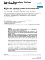
rapidly as they return to their original state; the image constructed from this time constant is T2 (Fig. 1-3). The cre1-1 Computed Tomography (CT) in the axial plane of a patient
with subarachnoid hemorrhage. Bone is white, acute blood (white) ation of a T1-weighted image versus a T2-weighted image is
outlines the subarachnoid space, brain is grey, and cerebrospinal fluid based on a variation in the times used to receive the “echo”
from the relaxed protons.
in third and lateral ventricles is black.
4
Introduction and Reader’s Guide
The Brain and Related Structures in MRI
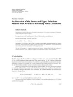
1-2 A sagittal T1 weighted Magnetic Resonance Image (MRI).
Brain is grey and cerebrospinal fluid is black.
NORMAL
T1
T2
Bone
Air
Muscle
White matter
Grey matter
Fat
CSF
Very black
Very black
Dark grey
Light grey
Dark grey
White
Very black
Very black
Very black
Dark grey
Dark grey
Light grey
Grey
Very white
ABNORMAL
T1
T2
Edema
Dark grey
Light grey to white
Tumor
Variable
Variable
Enhanced tumor
White
(Rarely done)
Dark grey
Light grey to white
The following table summarizes the white to black inten- Acute infarct
Subacute infarct
Dark grey
Light grey to white
sities seen in MRI images that are T1-weighted versus T2- Acute ischemia
Dark grey
Light grey to white
weighted. It should be emphasized that a number of varia- Subacute ischemia
Dark grey
Light grey to white
tions on these two general MRI themes are routinely seen in
the clinical environment.
The advantages of MRI are 1) it can be manipulated to visualize a wide variety of abnormalities or abnormal states
Chapter 2
within the brain; and 2) it can show great detail of the brain
This chapter presents 1) the gross anatomy of the spinal cord
in normal and abnormal states. The disadvantages of MRI
and its principal arteries; 2) the external morphology of the
are 1) it does not show acute or subacute subarachnoid hembrain, accompanied by MRIs and drawings of the vasculaorrhage or hemorrhage into the substance of the brain in any
ture patterns from the same perspective; 3) cranial nerves
detail; 2) it takes a much longer time to do and, therefore,
as seen in specimens and in MRI; and 4) the meninges and
is not useful in acute situations or in some types of trauma;
ventricular spaces. Emphasis is placed on correlating exter3) it is, comparatively, much more expensive than CT, and
nal brain and spinal cord anatomy with the respective vas4) the scan is extremely loud and may require sedation in
cular patterns and on correlating external brain structures
children.
and cranial nerves as seen in specimens with how the same
The ensuing discussion briefly outlines the salient features
structures appear in MRI. Information concerning the orgaof individual chapters. In some sections, considerable flexinization of the meninges includes clinical correlations, exbility has been designed into the format; at these points,
amples of extradural, so-called “subdural”, and subarachsome suggestions are made as to how the atlas can be used.
noid hemorrhages in CT and examples of cisterns in MRI.
In addition, new clinical correlations and examples have
The section showing the structure and relations of the venbeen included and a new chapter of USMLE-style review
tricular system now includes samples of hemorrhage into
questions has been added.
lateral, third, and fourth ventricles.
Chapter 3
The dissections in Chapter 3 offer views of some of those
brain structures introduced in Chapter 2. Certain structures
and/or structural relationships—for example, the orientation of the larger association bundles—are particularly
suited to such a presentation. This chapter uses a representative series of dissected views to provide a broader basis for
learning human neuroanatomy. Because it is not feasible to
illustrate every anatomic feature, the views and structures
selected are those that are usually emphasized in medical
1-3 A sagittal T2 weighted Magnetic Resonance Image (MRI). neurobiology courses. These views provide basic informaBrain is grey, blood vessels frequently appear black, and cerebrospinal tion necessary to make more detailed dissections, if appropriate, in a particular learning situation.
fluid is white.
Introduction and Reader’s Guide 5
Chapter 4
The study of general morphology of the hemisphere and
brainstem is continued in the two sections of Chapter 4. The
first section contains a representative series of unstained
coronal slices of brain, each of which is accompanied, on the
same page, by MRIs. The brain slice is labeled (by complete
names), and the MRIs are labeled with a corresponding abbreviation. The second section contains a series of unstained
brain slices cut in the axial plane, each of which is accompanied, again on the same page, by MRIs. Labeling of the axial
slices is as done for the coronal slices.
The similarities between the brain slices and the MRIs are
remarkable, and this style of presentation closely integrates
anatomy in the slice with that as seen in the corresponding
MRI. Because the brain, as sectioned at autopsy or in clinical pathologic conferences, is viewed as an unstained specimen, the preference here is to present the material in a format that will most closely parallel what is seen in these
clinical situations.
Chapter 5
This chapter has been revised with special emphasis on increasing the correlation between anatomical and clinical information. This new edition retains the quality and inherent
strengths of the line drawings and the stained sections being
located on facing pages in this chapter. However, an innovative approach (described below) is introduced that allows
the use of these images in their classic Anatomical Orientation and, at the same time, their conversion to the Clinical
Orientation so universally recognized and used in clinical
imaging techniques.
Chapter 5 consists of six sections covering, in sequence,
the spinal cord, medulla oblongata, cerebellar nuclei, pons,
midbrain, and diencephalon and basal nuclei, all with MRI.
In this format, the right-hand page contains a complete image of the stained section. The left-hand page contains a labeled line drawing of the stained section, accompanied by a
figure description, and a small orientation drawing. The section part of the line drawing is printed in a 60% screen of
black, and the leader lines and labels are printed at 100%
black. This gives the illustration a sense of depth and texture, reduces competition between lines, and makes the illustration easy to read at a glance.
Beginning with the first spinal cord level (coccygeal, Figure 5-1), the long tracts that are most essential to understanding how to diagnose the neurologically impaired
patient are colored. These tracts are the posterior column–
medial lemniscus system, the lateral corticospinal tract, and
the anterolateral system. In the brainstem, these tracts are
joined by the colorized spinal trigeminal tract, the ventral
trigeminothalamic tract, and all of the motor and sensory
nuclei of cranial nerves. This scheme continues rostrally
into the caudal nuclei of the dorsal thalamus and the posterior limb of the internal capsule. In addition to the coloring
of the artwork, each page has a key that specifies the structure and function of each colored structure. This approach
emphasizes anatomical–clinical integration.
Semidiagrammatic representations of the internal blood
supply to the spinal cord, medulla, pons, midbrain, and forebrain follow each set of line drawings and stained sections.
This allows the immediate, and convenient, correlation of
structure with its blood supply as one is studying the internal anatomy of the neuraxis. In addition, tables that summarize
the vascular syndromes of the spinal cord, medulla, pons, midbrain,
and forebrain are located on the pages facing each of these vascular drawings. While learning or reviewing the internal
blood supply to these parts of the neuraxis, one can also correlate the deficits seen when the same vessels are occluded.
It is essential to successful diagnosis to develop a good understanding of what structure is served by what vessel.
The diencephalon and basal nuclei section of this chapter
uses ten cross-sections to illustrate internal anatomy. It
should be emphasized that 8 of these 10 sections (those parallel to
each other) are all from the same brain.
The internal anatomy of the brainstem is commonly
taught in an anatomical orientation. That is, posterior structures, such as the vestibular nuclei and colliculi, are “up” in
the image, while anterior structures, such as the pyramid
and crus cerebri, are “down” in the image. However, when
the brainstem is viewed in the clinical setting, as in CT or
MRI, this orientation is reversed. In the clinical orientation,
posterior structures (4th ventricle, colliculi) are “down” in
the image while anterior structures (pyramid, basilar pons,
crus cerebri) are “up” in the image.
Recognizing that many users of this book are pursuing a
health care career (as a practitioner or teacher of future clinicians), it is essential to introduce MRI and CT of the brainstem into chapter 5. This accomplishes two important points.
First, it allows correlation of the size, shape, and configuration of brainstem sections (line drawings and stained slices)
with MRI and CT at comparable levels. Second, it offers the
user the opportunity to visualize how nuclei, tracts (and their
somatotopy) and vascular territories are represented in MRI
and CT. Understanding the brain in the Clinical Orientation
(as seen in MRI or CT) is extremely important in diagnosis.
To successfully introduce MRI and CT in the brainstem portion of chapter 5, a continuum from Anatomical Orientation
to Clinical Orientation to MRI needs to be clearly illustrated.
This is achieved by 1) placing a small version of the colorized
line drawing on the facing page (page with the stained section)
in Anatomical Orientation; 2) showing how this image is
flipped top to bottom into a Clinical Orientation; and 3) following this flipped image with (usually) T1 and T2 MRls at
levels comparable to the accompanying line drawing and
6
Introduction and Reader’s Guide
stained section (Fig. 1-4). This approach retains the anatomical strengths of the spinal cord and brainstem sections of
chapter 5 but allows the introduction of important concepts
regarding how anatomical information is arranged in images
utilized in the clinical environment.
Every effort has been made to use MRI and CT that match,
as closely as possible, the line drawings and stained sections in
the spinal cord and brainstem portions of chapter 5. Recognizing that this match is subject to the vicissitudes of angle and
individual variation, special sets of images were used in chapter 5. The first set consisted of T1- and T2-weighted MRI
generated from the same individual; these are identified, respectively, as “MRI, T1-weighted” and “MRI, T2-weighted”
in chapter 5. The second set consisted of CT images from a
patient who had an injection of the radiopaque contrast media Isovue-MR 200 (iopamidol injection 41 %) into the lumbar cistern. This contrast media diffused throughout the spinal
and cranial subarachnoid spaces, outlining the spinal cord and
brainstem (Fig. 1-5). Images at spinal levels show neural
structures as grey surrounded by a light subarachnoid space;
this is a “CT myelogram”. A comparable image at brainstem
levels (grey brain, light CSF) is a “CT cisternogram”. These
designations are used in chapter 5. While all matches are not
perfect, not all things in life or medicine are, the vast majority of matches between MRI, CT, and drawings/sections are
excellent and clearly demonstrate the intended points.
1-5 Computed Tomography (CT) of a patient following injection
of a radiopaque contrast media into the lumbar cistern. In this example, at the medullary level (a cisternogram), neural structures appear
grey and the subarachnoid space appears light.
The juxtaposition of MRI to stained section extends into
the forebrain portion of chapter 5. Many anatomic features
seen in the forebrain stained sections are easily identified in
the adjacent MRI. These particular MRI are not labeled so
as to allow the user to develop and practice his/her interpretive skills. The various subsections of chapter 5 can be
used in a variety of ways and will accommodate a wide range
of student and/or instructor preferences.
Chapter 6
The three-dimensional anatomy of internal structures in the
CNS can also be studied in stained sections that correlate similar structures in different planes. The photographs of stained
axial and sagittal sections and of MRIs in Chapter 6 are organized to provide four important levels of information. First,
the general internal anatomy of brain structures can be easily
Anatomical orientation
Clinical orientation
identified in each photograph. Second, axial photographs are
on left-hand pages and arranged from dorsal to ventral (Figures 6-1 to 6-9), whereas sagittal photographs are on righthand pages and arranged from medial to lateral (Figures 6-2
to 6-10). This setup, in essence, provides complete representation of the brain in both planes for use as independent
MRI, T1 weighted image
study sets (axial only, sagittal only) or as integrated/correlated sets (compare facing pages). Third, because axial and
sagittal sections are on facing pages and the plane of section of
each is indicated on its companion by a heavy line, the reader
can easily visualize the positions of internal structures in more
than one plane and develop a clear concept of three-dimenMRI, T2 weighted image
sional topography. In other words, one can identify structures
dorsal or ventral to the axial plane by comparing them with
the sagittal, and structures medial or lateral to the sagittal
plane by comparing them with the axial. Such comparisons facilitate a more full understanding of three-dimensional relaCT cisternogram
tionships in the brain. Fourth, the inclusion of MRIs with rep1-4 An example showing anatomical and clinical orientations of a resentative axial and sagittal stained sections provides
brainstem level and the corresponding T1 MRI, T2 MRI, and CT cister- excellent examples of the fact that structures seen in the
nogram. For additional examples and details see chapter 5, pages 84–133. teaching laboratory are easy to recognize in clinical images.
Introduction and Reader’s Guide 7
These MRIs are also not labeled so as to allow the user to de- general format as the preceding figures. Photocopies of
these blank master drawings can be used by the student for
velop his/her interpretive skills.
learning and/or review of any pathway and by the instructor to teach additional pathways not included in the atlas or
Chapter 7
as a substrate for examination questions. The flexibility of
This chapter provides summaries of a variety of clinically information as presented in Chapter 7 extends equally to
relevant CNS tracts and/or pathways and has four features student and instructor.
that enhance student understanding. First, the inclusion of
pathway information in atlas format broadens the basis one
Chapter 8
can use to teach functional neurobiology. This is especially
This chapter contains a series of angiograms (arterial and
the case when pathways are presented in a style that enhances the development of diagnostic skills. Second, each venous phases), magnetic resonance angiography (MRA)
drawing illustrates, in line color, a given pathway com- images, and magnetic resonance venography (MRV) impletely, showing its 1) origins, longitudinal extent, course ages. The angiograms are shown in lateral and anterior–
throughout the neuraxis and termination; 2) laterality—an posterior projections—some as standard views with correall-important issue in diagnosis; 3) point of decussation, if sponding digital subtraction images. MRA and MRV techapplicable; 4) position in representative cross sections of the nology are noninvasive methods that allow for the visualizabrainstem and spinal cord; and 5) the somatotopic organi- tion of arteries (MRA) and veins and venous sinuses (MRV).
zation of fibers within the pathway, if applicable. The blood There are, however, many situations when both arteries and
supply to each pathway is reviewed on the facing page. veins are seen with either method. Use of MRA and MRV
Third, a brief summary mentions the main neuroactive sub- is commonplace, and this technology is an important diagstances associated with cells and fibers composing particular nostic tool. A number of new vascular images have been insegments of the pathway under consideration. The action of cluded in this revised version of Chapter 8.
the substance, if widely agreed on, is indicated as excitatory
(ϩ) or inhibitory (Ϫ). This allows the reader to closely correlate
Chapter 9
a particular neurotransmitter with a specific population of projecA primary goal in the study of functional human neurobition neurons and their terminals. The limitations of this approach, within the confines of an atlas, are self-evident. The ology is to become a competent health care professional.
transmitters associated with some pathways are not well Another, and equally significant, goal is to pass examinaknown; consequently, such information is not provided for tions. These may be course examinations, the National
some connections. Also, no attempt is made to identify sub- Board Subject Exam (some courses require these), or stanstances that may be colocalized, to discuss their synthesis or dardized tests, such as the USMLE Step 1 and Step 2, given
degradation, or to mention all neurotransmitters associated at key intervals and taken by all students.
The questions comprising chapter 9 were generated in
with a particular cell group. The goal here is to introduce
the reader to selected neurotransmitters and to integrate and the recognition that examinations are an essential part of the
correlate this information with a particular pathway, circuit, educational process. Whenever possible, and practical,
or connection. Fourth, the clinical correlations that accompany these questions are in the USMLE Step 1 style (single best
each pathway drawing provide examples of deficits resulting from answer). These questions emphasize 1) anatomical and clinlesions, at various levels in the neuraxis, of the fibers composing that ical concepts and correlations; 2) the application of basic huspecific pathway. Also, examples are given of syndromes or man neurobiology to medical practice; and 3) how neurodiseases in which these deficits are seen. The ways in which logical deficits and diseases relate to damage in specific parts
these clinical correlations can be used to enrich the learning of the nervous system. In general, the questions are grouped
by chapter. However, in some instances, questions draw on
process are described in Figure 7-3 on page 176.
The drawings in this section were designed to provide the information provided in more than one chapter. This is
maximum amount of information, to keep the extraneous sometimes essential in an effort to make appropriate
points to a minimum, and to do it all in a single, easy-to-fol- structural/functional/clinical correlations. At the end of
low illustration. A complete range of relevant information each group of questions the correct answers are provided
is contained in each drawing and in its description as ex- and explained. Included with the explanation is a reference
to the page (or pages) containing the answer, be that answer
plained in the second point above.
Because it is not possible to anticipate all pathways that in the text or in a figure. Although not exhaustive, this list
may be taught in a wide range of neurobiology courses, flex- of questions should provide the user of this atlas with an exibility has been designed into Chapter 7. The last figure in cellent opportunity for self-assessment covering a broad
each section is a blank master drawing that follows the same range of clinically relevant topics.
8
Introduction and Reader’s Guide
Rationale for Labels and Abbreviations
o universally accepted way to identify specific features
or structures in drawings or photographs exists. The
variety of methods seen in currently available atlases reflects
the personal preferences of the authors. Such is the case in
the present endeavor. The goal of this atlas is to present basic functional and clinical neuroanatomy in an understandable and useful format.
Among currently available atlases, most figures are labeled with either the complete names of structures or with
numbers or letters that are keyed to a list of the complete
names. The first method immediately imparts the greatest
amount of information; the second method is the most succinct. When using the complete names of structures, one
must exercise care to not compromise the quality or size of
the illustration, the number of structures labeled, or the size
of labels used. Although the use of single letters or numbers
results in minimal clutter on the figure, a major drawback is
the fact that the same number or letter may appear on several different figures and designate different structures in all
cases. Consequently, no consistency occurs between numbers and letters and their corresponding meanings as the
reader examines different figures. This atlas uses a combination of complete words and abbreviations that are clearly
recognized versions of the complete word.
In response to suggestions made by those using this book
over the years, the number of abbreviations in the sixth edition has been reduced, and the number of labels using the
complete name has been increased. Simultaneously, complete names and abbreviations have been used together in
some chapters to the full advantage of each method. For example, structures are labeled on a brain slice by the complete name, but the same structure in the accompanying
MRI is labeled with a corresponding abbreviation (see
N
Chapters 2 and 4). This uses the complete word(s) on the
larger image of a brain structure while using the shorter abbreviation on the smaller image of the MRI.
The abbreviations used in this atlas do not clutter the illustration; they permit labeling of all relevant structures and
are adequately informative while stimulating the thinking–learning process. The abbreviations are, in a very real
sense, mnemonics. When learning gyri and sulci of the occipital lobe, for example, one realizes that the abbreviation
“LinGy” in the atlas could only mean “lingual gyrus.” It could
not be confused with other structures in other parts of the
nervous system. Regarding the pathways, “RuSp” could
mean only “rubrospinal tract” and “LenFas,” the “lenticular
fasciculus.” As the reader learns more and more terminology from lectures and readings, he or she will be able to use
these abbreviations with minimal reference to the accompanying list. In addition, a subtle advantage of this method of
labeling is that, as the reader looks at the abbreviation and
momentarily pauses to ponder its meaning, he or she may
form a mental image of the structure and the complete
word. Because neuroanatomy requires one to conceptualize
and form mental images to more clearly understand CNS
relationships, this method seems especially useful.
References:
Bruxton, RB. Introduction to Functional Magnetic Resonance
Imaging, Principles and Techniques. Cambridge: Cambridge
University Press, 2002.
Grossman, CB. Magnetic Resonance Imaging and Computed Tomography of the Head and Spine. 2nd Ed. Baltimore:
Williams & Wilkins, 1996.
Lee, SH, Roa, KCVG, and Zimmerman, RA. Cranial MRI
and CT. 4th Ed. New York: McGraw-Hill Health Professions Division, 1999.
CHAPTER
2
External Morphology
of the
Central Nervous System
10 External Morphology of the Central Nervous System
Posterior View
C2 Posterior root (PR)
Posterior spinal
artery
Dura
Arachnoid
C3 PR
Denticulate
ligament
C4 PR
Posterior spinal
medullary artery
C5 PR
Anterior View
C2 Anterior root (AR)
Dura
Denticulate
ligament
C3 AR
Arachnoid
Anterior spinal
medullary artery
C4 AR
Anterior spinal
artery
C5 AR
2-1 Posterior (upper) and anterior (lower) views showing the general features of the spinal cord as seen at levels C2–C5. The dura and
arachnoid are reflected, and the pia is intimately adherent to the spinal
cord and rootlets. Posterior and anterior spinal medullary arteries (see
Figure 2-3 on facing page) follow their respective roots. The posterior
spinal artery is found medial to the entering posterior rootlets (and the
dorsolateral sulcus), while the anterior spinal artery is in the anterior
median fissure (see also Figure 2-2, facing page).
The Spinal Cord 11
Posterior View
Sulci:
Posterior median
Posterior intermediate
Posterolateral
C7 Posterior root
Spinal (posterior root) ganglion
Fasciculus gracilis
Fasciculus cuneatus
Anterior View
Anterior spinal artery
C7 Anterior root
Anterior radicular
artery
Anterior funiculus
Anterior median fissure
2-2 Posterior (upper) and anterior (lower) views showing details
of the spinal cord as seen in the C7 segment. The posterior (dorsal) root
ganglion is partially covered by dura and connective tissue.
Posterior spinal arteries
Arterial
vasocorona
Basilar artery
Posterior inferior
cerebellar arteries
Vertebral arteries
Anterior spinal artery
Posterior spinal
medullary artery
Posterior radicular
artery (on dorsal root)
Sulcal arteries
Anterior spinal
medullary artery
Anterior radicular artery
(on ventral root)
Segmental artery
2-3 Semidiagrammatic representation showing the origin and general location of principal arteries supplying the spinal cord. The anterior and posterior radicular arteries arise at every spinal level and serve
their respective roots and ganglion. The anterior and posterior spinal
medullary arteries (also called medullary feeder arteries or segmental
medullary arteries) arise at intermittent levels and serve to augment
the blood supply to the spinal cord. The artery of Adamkiewicz is an
unusually large spinal medullary artery arising usually on the left in low
thoracic or upper lumbar levels (T9–L1). The arterial vasocorona is a
diffuse anastomotic plexus covering the cord surface.
12 External Morphology of the Central Nervous System
A
B
C
Thoracic
cord
T9
Dura and
arachnoid
LuSaCd
Lumbar and
sacral cord
(LuSaCd)
L1
SaCoCd
Sacral and
coccygeal
cord
(SaCoCd)
Lumbar
cistern
FTInt
Conus
medullaris
CaEq
Filum
terminale
internum
(FTInt)
L5
Cauda
equina
(CaEq)
S1
Posterior
root
ganglion
Dura and
arachnoid
2-4 Overall posterior (A,B) and sagittal MRI (C, T2-weighted)
views of the lower thoracic, lumbar, sacral, and coccygeal spinal cord
segments and the cauda equina. The dura and arachnoid are retracted
in A and B. The cauda equina is shown in situ in A, and in B the nerve
roots of the cauda equina have been spread laterally to expose the conus
medullaris and filum terminale internum. This latter structure is also
called the pial part of the filum terminale. See Figures 5-1 and 5-2 on
pages 84–87 for cross-sectional views of the cauda equina.
In the sagittal MRI (C), the lower portions of the cord, the filum
terminale internum, and cauda equina are clearly seen. In addition, the
intervertebral discs and the bodies of the vertebrae are clear. The lumbar cistern is an enlarged part of the subarachnoid space caudal to the
end of the spinal cord. This space contains the anterior and posterior
roots from the lower part of the spinal cord that collectively form the
cauda equina. The filum terminale internum also descends from the
conus medullaris through the lumbar cistern to attach to the inner surface of the dural sac. The dural sac ends at about the level of the S2 vertebra and is attached to the coccyx by the filum terminale externum
(also see Fig. 2-47 on page 47). A lumbar puncture is made by inserting a large gauge needle (18-22 gauge) between the L3 and L4 vertebra or L4 and L5 vertebra and retrieving a sample of cerebrospinal fluid
from the lumbar cistern. This sample may be used for a number of diagnostic procedures.
The Brain: Lobes 13
Central sulcus
Precentral sulcus
Postcentral sulcus
Parietooccipital
sulcus
Lobes
Frontal
A
Parietal
Temporal
Occipital
Preoccipital
notch
Lateral sulcus
Limbic
Insular
Central sulcus
Paracentral sulcus
Marginal sulcus (marginal
ramus of the cingulate
sulcus)
Cingulate sulcus
Corpus callosum
Parietooccipital
sulcus
B
Fornix
Diencephalon
Preoccipital notch
Calcarine
sulcus
Collateral sulcus
2-5 Lateral (A) and medial (B) views of the cerebral hemisphere
showing the landmarks used to divide the cortex into its main lobes.
On the lateral aspect, the central sulcus (of Rolando) separates
frontal and parietal lobes. The lateral sulcus (of Sylvius) forms the border between frontal and temporal lobes. The occipital lobe is located
caudal to an arbitrary line drawn between the terminus of the parietooccipital sulcus and the preoccipital notch. A horizontal line drawn
from approximately the upper two-thirds of the lateral fissure to the
rostral edge of the occipital lobe represents the border between parietal and temporal lobes. The insular cortex (see also Figs. 2-46 on page
45 and 3-1 on page 56) is located internal to the lateral sulcus. This part
of the cortex is made up of long and short gyri that are separated from
each other by the central sulcus of the insula. The insula, as a whole, is
separated from the adjacent portions of the frontal, parietal, and temporal opercula by the circular sulcus.
On the medial aspect, the cingulate sulcus separates medial portions
of frontal and parietal lobes from the limbic lobe. An imaginary continuation of the central sulcus intersects with the cingulate sulcus and
forms the border between frontal and parietal lobes. The parietooccipital sulcus and an arbitrary continuation of this line to the preoccipital notch separate the parietal, limbic, and temporal lobes from the
occipital lobe.
14 External Morphology of the Central Nervous System
Postcentral gyrus
3,1,2
Precentral gyrus
5
Surpamarginal gyrus
Pars opercularis
6
7
4
8
40
Angular gyrus
39
19
Pars triangularis
18
22
45
44
17
41
A
42
Pars orbitalis
47
3,1,2
Anterior paracentral gyrus
5
8
6
Posterior paracentral gyrus
4
7
19
Cuneus
18
B
17
Calcarine sulcus
18
19
2-6 Lateral (A) and medial (B) views of the cerebral hemisphere
showing the more commonly described Brodmann areas. In general,
area 4 comprises the primary somatomotor cortex, areas 3,1, and 2 the
primary somatosensory cortex, and area 17 the primary visual cortex.
Area 41 is the primary auditory cortex, and the portion of area 6 in the
caudal part of the middle frontal gyrus is generally recognized as the
frontal eye field.
The inferior frontal gyrus has three portions: a pars opercularis, pars
Lingual gyrus
triangularis, and a pars orbitalis. A lesion that is located primarily in areas 44 and 45 (shaded) will give rise to what is called a Broca aphasia,
also called expressive or nonfluent aphasia.
The inferior parietal lobule consists of supramarginal (area 40) and
angular (area 39) gyri. Lesions in this general area of the cortex
(shaded), and sometimes extending into area 22, will give rise to what
is known as Wernicke aphasia, also sometimes called receptive or fluent aphasia.
The Brain: Lobes 15
Precentral gyrus (primary somatomotor cortex)
Posrcentral gyrus (primary somatosensory cortex)
A
Anterior paracentral gyrus (somatomotor)
Posterior paracentral gyrus (somatosensory)
B
Left
inferior
visual
quadrant
2-7 Lateral (A) and medial (B) views of the cerebral hemisphere
showing the somatotopic organization of the primary somatomotor
and somatosensory cortices. The lower extremity and foot areas are located on medial aspects of the hemisphere in the anterior paracentral
(motor) and the posterior paracentral (sensory) gyri. The remaining
portions of the body extend from the margin of the hemisphere over
the convexity to the lateral sulcus in the precentral and postcentral
gyri.
In general, the precentral gyrus can be divided into three regions:
the lateral third representing the face area, the middle third represent-
ing the hand and upper extremity areas, and the medial third representing the trunk and the hip. Lesions of the somatomotor cortex result in motor deficits on the contralateral side of the body while lesions
in the somatosensory cortex result in a loss of sensory perception from
the contralateral side of the body.
The medial surface of the right hemisphere (B) illustrates the position of the left portions of the visual field. The inferior visual quadrant
is located in the primary visual cortex above the calcarine sulcus while
the superior visual quadrant is found in the cortex below the calcarine
sulcus.
16 External Morphology of the Central Nervous System
Longitudinal fissure
Superior frontal
gyrus (SFGy)
Middle frontal
gyrus (MFGy)
Superior frontal
sulcus (SFSul)
Precentral
sulcus (PrCSul)
Precentral
gyrus (PrCGy)
Central
sulcus (CSul)
Precentral
gyrus (PrCGy)
Postcentral
gyrus (PoCGy)
Central
sulcus (CSul)
Supramarginal
gyrus
Postcentral sulcus
Superior parietal lobule
Occipital gyri
Anterior
cerebral
arteries
MFGy
ACA
territory
SFGy
SFSul
PrCSul
CSul
PoCGy
PrCGy
Falx
cerebri
2-8 Dorsal view of the cerebral hemispheres showing the main gyri
and sulci and an MRI (inverted inversion recovery—lower left) and a
CT (lower right) identifying structures from the same perspective.
Note the area of infarction representing the territory of the anterior
cerebral artery (ACA).
The Brain: Gross Views, Vasculature, and MRI 17
Frontopolar
branches of ACA
Branches of MCA (M4)
Orbitofrontal
Prerolandic
Rolandic
Callosomarginal branches
(from ACA)
Parietal and
temporal
Paracentral branches
(from ACA)
Internal parietal branches
(from ACA)
Branches of PCA
Temporal (P3)
Parieto-occipital sulcus
Parieto-occipital (P4)
Calcarine (P4)
2-9 Dorsal view of the cerebral hemispheres showing the location
and general branching patterns of the anterior (ACA), middle (MCA),
and posterior (PCA) cerebral arteries. Gyri and sulci can be identified
by a comparison with Figure 2-8 (facing page).
Superior cerebral veins
Superior
sagittal sinus
Rolandic vein
To superficial middle
cerebral vein and
inferior anastomotic
vein
Greater anastomotic
vein (Trolard)
Superior cerebral veins
To sinus confluens
2-10 Dorsal view of the cerebral hemispheres showing the location
of the superior sagittal sinus and the locations and general branching
patterns of veins. Gyri and sulci can be identified by a comparison with
Figure 2-8 (facing page). See Figures 8-4 and 8-5 (pp. 243–244) for
comparable angiograms (venous phase) of the superior sagittal sinus.