Altium designer intermediate guide
Bạn đang xem bản rút gọn của tài liệu. Xem và tải ngay bản đầy đủ của tài liệu tại đây (7.78 MB, 352 trang )
Altium Designer Guide
Beginning & Intermediate Version
Glenn Mercier
Research Engineer, TBE-B311
University of Las Vegas, Nevada
Part 1: Beginning Guide
This guide is a beginner’s guide to PCB
design using Altium Designer and is
geared towards the following individuals:
◦ Possess ample theoretical electronics
knowledge
◦ Has little or no PCB design experience
◦ Has little or no Altium Designer experience
Beginning Guide
Before proceeding to the actual software
tutorial, It is important to understand
when it is absolutely necessary to use a
PCB rather than design with a
breadboard
Most students have a reluctance to
learning new software and spending
money for something they could possibly
build on a breadboard.
Breadboard vs. PCB
For many electronic designs, one has a
choice to build a circuit on either a
breadboard or on a printed circuit board.
Most students have a certain comfort
zone working with breadboards, but there
comes a time when the complexity of the
project or the physical requirements
requires electronic design through CAD
(computer aided design).
Breadboard Advantages
Very quick to prototype using standard
components
Can easily make changes to schematic or
the functional working of the circuit
Easy to connect to electronic equipment
such as function generator, oscilloscope,
power supplies, etc.
Breadboard Disadvantages
Unprofessional appearance
Difficult to troubleshoot due to human
error and poor connections
Works very poorly for high speed design
Difficult to modify complex SMD
components for prototyping
Excessive capacitance
Difficult to replicate
Printed Circuit Board Advantages
Professional appearance
Repeatable and controllable stray
inductance and capacitance
Can handle most power requirements
Can make very compact
Excellent high speed capabilities
Easy to assemble and replicate
Printed Circuit Board Disadvantages
Increased design time
Drastically increased schematic-to-finished
product timeframe
Development Cost
Difficult to modify once board is fabricated
Must learn at least a basic form of CAD software
Quality of PCB can be affected by limited
knowledge of software package
Capabilities vary greatly with different software
packages.
High end CAD software is very expensive
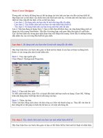
Required PCB Design
Small Packages,
such as a BGA,
MLF, QFP are
practically
impossible to
prototype on a
breadboard due
to their small
size and MUST
be designed on a
PCB.
/>
Required PCB Design
Just dealing with the sheer number of pins
on modern practical designs required a
PCB.
It is common to see single components
containing up to 1,500 pins
High speed design cannot be performed
using traditional prototyping methods
Altium Designer
This is based off the current version of Altium Designer,
6.9.0.12759
The Altium Designer Suite contains many unified features such as:
◦
◦
◦
◦
◦
◦
◦
◦
◦
◦
◦
◦
FPGA schematic design
VHDL/Verilog compilers
C/ASM compilers
Scripting
Simulation
2D Field Solver
Simulation Engine
Library Management
Database and advanced query language
CAM display management
Schematic Capture
PCB Layout
System Requirements
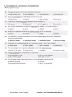
Getting Started
Start the software by
clicking
START
PROGRAMS
ALTIUM DESIGNER
Altium Designer 6
Create a start bar shortcut
if you plan on using the
software a lot. (shown on
right)
Project File
Project files are like a container for your project.
There are many different things you will need for
even a basic project, such as:
◦
◦
◦
◦
◦
◦
◦
◦
◦
◦
◦
PCB Footprint libraries
Schematic libraries
Schematic documents
PCB documents
Scripts
CAM files
Settings
Generated reports
Generated files
Version Control features
Etc.
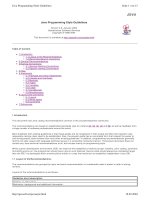
Creating a Project
When the
software starts,
follow the
menu sequence
in the image to
create a new
‘PCB Project’
Many people
skip this step
and just create
a schematic file.
This a huge
mistake!
Absolutely
everything in
Altium
Designer is
based on
project files
Project Name
We need to save our project and rename the project to something
more meaningful.
Right click on PCB_Project.prjPCB and save the project as
‘PROJECT- EE495’ to a new folder (preferably on a flash drive)
called ‘EE495 Project’ inside a root folder called ‘EE495 Altium’
EX:
F:\EE495 Altium\EE495 Project\PROJECT-EE495.prjPCB
Inside this folder, we will place all relevant project data
Organization
It is useful to place all project information inside this folder.
Inside this root folder, create subfolders called ‘CODE’ and
‘DATASHEETS’
Organization and centralization is also important for backing up all
your data properly, version control, and copying project data to a
CD for all finished projects (which you should do for future
reference)
(Group) Quiz Project #1
◦
For the first quiz project, we are going to create
a schematic that will contain:
Atmega8 - Atmel Microcontroller , 16 MHz, QFP
USB-B Connector
FT232 USB- UART interface chip , TSSOP28
2x5 Programming Input Header (0.1” Pitch)
SMD (Surface Mount Device) LEDs , 0805 Size
This project contains all the necessary parts to create a
PCB that can communicate directly with a computer
through a USB (Male B- Male A) Cable.
◦ You are encouraged to actually build this PCB as an
inexpensive, functional development board.
This project is to be finished by next Wednesday (5/28)
with a possible in-class portion
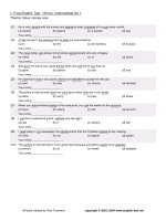
Adding a Schematic Drawing
Follow the menu sequence shown to
create a new schematic. This will
automatically be added to the project
tree we created.
Schematic Entry
The ‘sheet1’ schematic document is now added
to the project tree as shown below.
Rename this file to something with a more
meaningful name such as ‘Main’. There are many
times when you will have multiple schematic
entries and it helps to have a descriptive name
Any open project files will appear in the menu
area above where the blank schematic page
appears.
Libraries
Similar to a real laboratory, to build a design
from a schematic you must first add real
parts to the project.
For this, we must add what are called
‘libraries’ to our project. Libraries contain
vital information about the parts we are
going to add.
Once libraries are added to the project, any
component inside that library can be freely
inserted into your design.
Types of Libraries
There are three main types of libraries for PCB
design:
◦ Schematic Library- Contains schematic drawings of parts,
when we look at a schematic, we are looking at a collection
of schematic parts
◦ PCB Footprint Library- This contains the physical dimensions
of a real component. This information is readily available in
datasheets.
◦ Integrated Library- These are the most useful libraries
because they combine a physical part (footprint) with a
schematic drawing.
Libraries
Libraries are located in the folder:
C:\Program Files\Altium Designer 6\Library
Updated libraries are available online at
/>
Altium has since changed some of their
library files, I have included a ZIP file on
the course website with library files we’ll
be using.
Download and unzip the file into the
‘library’ folder in your project directory
Libraries
Copy the following Libraries to a folder called ‘Libraries’ in your Custom Altium
folder:
Integrated Libraries (*.IntLib)
Atmel Microcontroller 8-bit AVR
Miscellaneous Connectors
Miscellaneous Devices
NSC Operational Amplifier
ON Semi Operational Amplifier
Schematic Libraries (*.SchLib)
<none>
Footprint Libraries (*.PcbLib)
Chip Capacitor – 2 Contacts
Chip Diode – 2 Contacts
Chip Inductor – 2 Contacts
Chip Resistor – 2 Contacts
Crystal Oscillator
Miscellaneous Connector PCB
Miscellaneous Devices PCB
Miscellaneous Devices
Miscellaneous
NOTE: When you create your own schematic and footprint libraries, you should
place them in the same library directory in your project folder
Adding Libraries To A Project
We have organized all the libraries in a
folder, now we need to add these to the
project
Follow the following prompt to add
libraries to the project