C5 formation damage
Bạn đang xem bản rút gọn của tài liệu. Xem và tải ngay bản đầy đủ của tài liệu tại đây (1.76 MB, 42 trang )
Designed & Presented by
Mr. ĐỖ QUANG KHÁNH, HCMUT
Đỗ Quang Khánh – HoChiMinh City University of Technology
Email: or
1
What is Formation Damage?
Damage can be anything that obstructs the normal flow of fluids
to the surface.
Formation damage specifically refers to obstructions occurring in
the near-wellbore region of the rock matrix.=> Concerns the
formation of a volume of rock with a reduced permeability in the
near wellbore zone.
Ultimate economics usually favor control of formation damage
rather than stimulation to overcome limited productivity.
Sources of Formation Damage
Damage during drilling operations
Damage during completion operations
Damage during well stimulation
Damage caused by other operations
Damage during drilling operations
Mud solids may block pores, vugs, and natural or induced fractures.
Mud filtrate invasion into oil and gas zones may oil-wet the formation and cause water or
emulsion blocks.
Pore or fractures near the wellbore may be sealed by the trowelling action of the bit, drill collars
and drill pipe.
Cement or mud solids may plug large pores, vugs, and natural or induced fractures.
Chemical flushes used to scour hole ahead of cement may cause changes in clays in the
producing formation.
Filtrate from high fluid loss cement slurries may bring about changes in the producing formation.
Damage during completion operations
Damage during perforating
Perforations may be plugged with shaped charge debris and solids from perforating fluids.
Formation around perforation is crushed and compacted by perforating process.
Damage while running tubing and packer
If returns are lost while running tubing, solids in the well fluid may plug any fracture system near the
wellbore
Perforations may be plugged if solids are forced into perforations by the hydrostatic differential
pressure into the formation.
Damage during production initiation
Damage may be caused by incompatible circulation fluids and by loss of clays or another fines into
perforation pores, vugs.
Damage may result from depositing of mill scale, clay, or excess thread dope from tubing collars in
perforation when circulating to clean a well.
Completion fluids containing blown asphalt may cause damage by oil-wetting the formation and by
plugging perforations and formation.
Clean-up of a well at high rates can result in severe plugging within the formation by particles which,
for one reason or another, are free to move.
Damage during well stimulation
Perforations, formation pores, and fractures may be plugged with solids while killing or circulating a
well with mud or with unfiltered oil or water.
Damage may be caused by filtrate from circulating fluids.
Breaking down or fracturing the formation with acid may shrink the mud cake between the sand face
and cement or may affect mud channel in the annulus allowing vertical communication of unwanted
fluids.
Acidizing sandstone with hydrofluoric acid may leave insoluble precipitates in formation. Properly
designed treatment minimizes effect.
Damage may be caused by hydraulic fracturing fluids.
Damage may be caused by incompatible fluid in fracture acidizing of carbonates.
Damage caused by other operations
Damage caused by cleaning of paraffin solids from the tubing, casing, or wellbore
Damage during well servicing or workover
Damage during producing phase
Damage during water injection
Damage during gas injection
Common Formation Damage Mechanisms
1. Fines invasion and migration (particles, etc.)
2. Rock-fluid incompatibility (clay swelling, etc.)
3. Fluid-fluid incompatibility (emulsion generation, etc.)
4. Phase trapping and blocking (water entrapment in gas reservoirs)
5. Adsorption and wettability alteration
6. Biological activity (bacteria, slime production).
Particle Plugging within the Formation
The pore system provides a tortuous path to the wellbore
Particles can move through the pore system.
Particle movement is affected by wettability and by the fluid
phases in the pore system.
Particulate Capture Mechanisms
Straining
Bridging
DEPOSITION
ENTRAINMENT
FLOW
Solid particles
TYPICAL HYDRAULIC TUBE
Bridging Mechanism
Flat bridges
Arch bridges
(after Valdes and Santamarina, 2006)
No bridges
Perforation Diameter
Average Particle Diameter
Bridging of Particles at Perforation
No Bridging
well
6
bridging
4
Bridging Region
2
perforation
4
8
12
16
20
24
28
Maximum Gravel Content – LB/GAL
(After Gruesbeck and Collins, 1982)
32
Exponential-law equation
A 1 exp B Re p C
A, B, and C are empirical parameters
A 1 exp B Re p C
Pore-to-particle diameter ratio
6
D
T
Dp
Particle-Volume-Fraction Reynolds number
Re p
p p vDp
4
Bridging Region
2
4
8
12
16
20
Rep
(Tran et al. 2009, SPE 120847)
24
28
32
Formation Clays (Inherent Particles)
Oil-producing sandstones contain clays as a coating on
individual sand grains. (clean sand contains 1-5% clay, dirty
sand contains 5 to greater than 20% clay)
Common clays: smectite (bentonite), illite, mixed-layer clays
(primarily illite-smectile), kaolinite, and chlorite.
Clay Migration
Clay migrate when contacting with foreign water which alters the
ionic environment.
Foreign waters are filtrate loss from drilling fluids, cement,
completion fluids, workover fluids, and stimulation fluids.
Other effects: swelling due to hydration cations, cation type and
concentration, and pH.
Diagnosis of Formation Damage
Determine formation damage or skin effect in a particular
well.
Analysis of pressure buildup or fall off tests.
Production logging surveys.
Comparison of productivity of the subject well with productivities of
surrounding wells.
Rule out mechanical problems such as sand accumulation in the
wellbore or artificial lift difficulties.
Skin Formulation
St = ΣSi (Total skin is sum of components)
= Sd + Sc+ ϴ + Sp + ΣSpseudo
Formation Damage (Sd)
Mechanical damage to near-well formation
Partial Penetration Skin Sc+ ϴ
Partial completion (Sc)
Slanted (deviated) wellbore (Sdev)
Perforation Skin (Sd)
Non-Darcy Flow (Turbulence damage) (ΣSpseudo)
Near Wellbore Area
Drilling, cementing, and completion alter reservoir conditions near the well.
Distortion or restriction of flow.
Additional near wellbore pressure drop - “skin”.
Characterized with:
Damage permeability, ks
Damage radius, rs
Wellbore Skin Effect
Positive Skin Effect:
denotes that the pressure drop in the near wellbore zone is more
than it would have been, from the normal, undisturbed,
reservoir flow mechanism.
Modifications to IPR
Pwf (no skin)
Pwf (with skin)
Near Wellbore Pressure Drop
pwf, ideal
pwf, real
ps
Positive Skin Effect
Any phenomenon that causes a distortion of the flow lines from the
perfectly normal to the well direction, or a restriction to flow,
would result in a positive value of skin.
damage to the natural reservoir permeability
partial completion (distortion of flow lines)
inadequate number of perforations (distortion of flow lines)
phase changes (relative permeability reduction to the main fluid)
turbulence (rate dependent)
Negative Skin Effect
A negative skin effect denotes that the pressure drop in near
wellbore zone is less than it would have been from the
normal, undisturbed, reservoir flow mechanism.
It may be the result of:
Acid matrix stimulation
Hydraulic fracturing
A highly declined wellbore
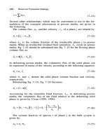
Math. Development of Damage Skin
Steady-state pressure drop between outer boundary of
damage zone (rs) and wellbore (rw)
Ideal case (no damage zone)
Real case (damage zone with permeability of ks)
Math. Development of Damage Skin
Pressure drop due to damage:
Skin effect defined as additional steady-state pressure drop
in the near-wellbore region