Điện tử công suất (inverter chapter 4 )
Bạn đang xem bản rút gọn của tài liệu. Xem và tải ngay bản đầy đủ của tài liệu tại đây (392.75 KB, 46 trang )
Chapter 4
DC to AC Conversion
(INVERTER)
•
•
•
•
•
General concept
Single-phase inverter
Harmonics
Modulation
Three-phase inverter
Power Electronics and
Drives (Version 3-2003):
Dr. Zainal Salam UTM-JB
1
DC to AC Converter (Inverter)
• DEFINITION: Converts DC to AC power by
switching the DC input voltage (or current) in a
pre-determined sequence so as to generate AC
voltage (or current) output.
• General block diagram
IDC
Iac
Vac
VDC
−
−
• TYPICAL APPLICATIONS:
– Un-interruptible power supply (UPS), Industrial
(induction motor) drives, Traction, HVDC
Power Electronics and
Drives (Version 3-2003):
Dr. Zainal Salam UTM-JB
2
Simple square-wave inverter (1)
• To illustrate the concept of AC waveform
generation
S1
S3
S4
S2
Power Electronics and
Drives (Version 3-2003):
Dr. Zainal Salam UTM-JB
3
AC Waveform Generation
S1,S2 ON; S3,S4 OFF
vO
S1
VDC
for t1 < t < t2
VDC
S3
+ vO −
t1
S4
t
t2
S2
S3,S4 ON ; S1,S2 OFF
for t2 < t < t3
vO
S1
VDC
S3
t2
+ vO −
S4
t3
t
S2
-VDC
Power Electronics and
Drives (Version 3-2003):
Dr. Zainal Salam UTM-JB
4
AC Waveforms
INVERTER OUTPUT VOLTAGE
Vdc
π
2π
-Vdc
FUNDAMENTAL COMPONENT
V1
4VDC
π
V1
3
V1
5
3RD HARMONIC
5RD HARMONIC
Power Electronics and
Drives (Version 3-2003):
Dr. Zainal Salam UTM-JB
5
Harmonics Filtering
DC SUPPLY
INVERTER
(LOW PASS) FILTER
LOAD
L
+
vO 1
C
+
vO 2
−
BEFORE FILTERING
vO 1
−
AFTER FILTERING
vO 2
• Output of the inverter is “chopped AC voltage with
zero DC component”. It contain harmonics.
• An LC section low-pass filter is normally fitted at
the inverter output to reduce the high frequency
harmonics.
• In some applications such as UPS, “high purity” sine
wave output is required. Good filtering is a must.
• In some applications such as AC motor drive,
filtering is not required.
Power Electronics and
Drives (Version 3-2003):
Dr. Zainal Salam UTM-JB
6
Variable Voltage Variable
Frequency Capability
Vdc2
Higher input voltage
Higher frequency
Vdc1
Lower input voltage
Lower frequency
t
• Output voltage frequency can be varied by “period”
of the square-wave pulse.
• Output voltage amplitude can be varied by varying
the “magnitude” of the DC input voltage.
• Very useful: e.g. variable speed induction motor
drive
Power Electronics and
Drives (Version 3-2003):
Dr. Zainal Salam UTM-JB
7
Output voltage harmonics/
distortion
• Harmonics cause distortion on the output voltage.
• Lower order harmonics (3rd, 5th etc) are very
difficult to filter, due to the filter size and high filter
order. They can cause serious voltage distortion.
• Why need to consider harmonics?
– Sinusoidal waveform quality must match TNB
supply.
– “Power Quality” issue.
– Harmonics may cause degradation of
equipment. Equipment need to be “de-rated”.
• Total Harmonic Distortion (THD) is a measure to
determine the “quality” of a given waveform.
Power Electronics and
Drives (Version 3-2003):
Dr. Zainal Salam UTM-JB
8
Total Harmonics Distortion (THD)
Voltage THD : If Vn is the nth harmonic voltage,
∞
(Vn, RMS )2
THDv = n= 2
V1, RMS
=
V2, RMS 2 + V3, RMS 2 + .... + V2, RMS 2
V1, RMS
If the rms voltage for the vaveform is known,
∞
(VRMS )2 − (V1, RMS )2
THDv = n= 2
V1, RMS
Current THD :
∞
(I n, RMS )2
THDi = n =2
I1, RMS
V
In = n
Zn
Z n is the impedance at harmonic frequency.
Power Electronics and
Drives (Version 3-2003):
Dr. Zainal Salam UTM-JB
9
Fourier Series
• Study of harmonics requires understanding of wave
shapes. Fourier Series is a tool to analyse wave
shapes.
Fourier Series
ao =
an =
bn =
1 2π
π
1
π
1
π
0
2π
0
2π
f (v )dθ (" DC" term)
f (v) cos(nθ )dθ
(" cos" term)
f (v) sin (nθ )dθ
("sin" term)
0
Inverse Fourier
∞
1
f (v) = ao + (an cos nθ + bn sin nθ )
2
n =1
where θ = ωt
Power Electronics and
Drives (Version 3-2003):
Dr. Zainal Salam UTM-JB
10
Harmonics of square-wave (1)
Vdc
π
2π
θ ω
-Vdc
ao =
an =
bn =
1 π
π
0
2π
Vdc dθ + − Vdc dθ = 0
π
Vdc π
π
0
Vdc π
π
0
2π
cos(nθ )dθ − cos(nθ )dθ = 0
π
2π
sin (nθ )dθ − sin (nθ )dθ
π
Power Electronics and
Drives (Version 3-2003):
Dr. Zainal Salam UTM-JB
11
Harmonics of square wave (2)
Solving,
V
π
2π
bn = dc − cos(nθ ) 0 + cos(nθ ) π
nπ
Vdc
[(cos 0 − cos nπ ) + (cos 2nπ − cos nπ )]
=
nπ
Vdc
[(1 − cos nπ ) + (1 − cos nπ )]
=
nπ
2V
= dc [(1 − cos nπ )]
nπ
[
]
When n is even, cos nπ = 1
bn = 0
(i.e. even harmonics do not exist)
When n is odd, cos nπ = −1
4Vdc
bn =
nπ
Power Electronics and
Drives (Version 3-2003):
Dr. Zainal Salam UTM-JB
12
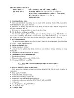
Spectra of square wave
Normalised
Fundamental
1st
3rd (0.33)
5th (0.2)
7th (0.14)
9th (0.11)
11th (0.09)
1
3
5
n
7
9
11
• Spectra (harmonics) characteristics:
– Harmonic decreases with a factor of (1/n).
– Even harmonics are absent
– Nearest harmonics is the 3rd. If fundamental is
50Hz, then nearest harmonic is 150Hz.
– Due to the small separation between the
fundamental an harmonics, output low-pass
filter design can be very difficult.
Power Electronics and
Drives (Version 3-2003):
Dr. Zainal Salam UTM-JB
13
Quasi-square wave (QSW)
Vdc
α
α
α
π
2π
-Vdc
Note that an = 0. (due to half - wave symmetry)
[
2V
1 π −α
π −α
bn = 2
Vdc sin (nθ )dθ = dc − cos nθ α
π α
nπ
]
2Vdc
[cos(nα ) − cos n(π − α )]
=
nπ
Expanding :
cos n(π − α ) = cos(nπ − nα )
= cos nπ cos nα + sin nπ sin nα = cos nπ cos nα
bn =
2Vdc
[cos(nα ) − cos nπ cos nα ]
nπ
2Vdc
=
cos(nα )[1 − cos nπ ]
nπ
Power Electronics and
Drives (Version 3-2003):
Dr. Zainal Salam UTM-JB
14
Harmonics control
If n is even,
bn = 0,
4Vdc
If n is odd, bn =
cos(nα )
nπ
In particular, amplitude of the fundamental is :
b1 =
4Vdc
π
cos(α )
Note :
The fundamental , b1 , is controlled by varying
Harmonics can also be controlled by adjusting α ,
Harmonics Elimination :
For example if α = 30 o , then b3 = 0, or the third
harmonic is eliminated from the waveform. In
general, harmonic n will be eliminated if :
90o
α=
n
Power Electronics and
Drives (Version 3-2003):
Dr. Zainal Salam UTM-JB
15
Example
A full - bridge single phase inverter is fed by square wave
signals. The DC link voltage is 100V. The load is R = 10R
and L = 10mH in series. Calculate :
a) the THDv using the " exact" formula.
b) the THDv by using the first three non - zero harmonics
c) the THDi by using the first three non - zero harmonics
Repeat (b) and (c) for quasi - square wave case with α = 30
degrees
Power Electronics and
Drives (Version 3-2003):
Dr. Zainal Salam UTM-JB
16
Half-bridge inverter (1)
S1 ON
Vdc S2 OFF
+
VC1
Vdc
G
+
VC2
-
2
S1
− V +
o
0
t
RL
S2
−
Vdc
2
S1 OFF
S2 ON
•
Also known as the “inverter leg”.
•
Basic building block for full bridge, three phase
and higher order inverters.
•
G is the “centre point”.
•
Both capacitors have the same value. Thus the DC
link is equally “spilt” into two.
•
The top and bottom switch has to be
“complementary”, i.e. If the top switch is closed
(on), the bottom must be off, and vice-versa.
Power Electronics and
Drives (Version 3-2003):
Dr. Zainal Salam UTM-JB
17
Shoot through fault and
“Dead-time”
•
In practical, a dead time as shown below is required
to avoid “shoot-through” faults, i.e. short circuit
across the DC rail.
•
Dead time creates “low frequency envelope”. Low
frequency harmonics emerged.
•
This is the main source of distortion for high-quality
sine wave inverter.
+ S1
Ishort
G
Vdc
RL
−
S1
signal
(gate)
S2
signal
(gate)
S2
"Shoot through fault" .
Ishort is very large
td
td
"Dead time' = td
Power Electronics and
Drives (Version 3-2003):
Dr. Zainal Salam UTM-JB
18
Single-phase, full-bridge (1)
•
Full bridge (single phase) is built from two halfbridge leg.
•
The switching in the second leg is “delayed by 180
degrees” from the first leg.
LEG R
VRG
Vdc
2
LEG R'
π
2π
ωt
π
2π
ωt
π
2π
ωt
+
+
Vdc
2
S1
-
Vdc
G
-
R
S3
+ Vo -
R'
+
Vdc
2
VR 'G
Vdc
2
−
S4
S2
−
Vdc
2
Vdc
2
Vo
Vdc
Vo = V RG − VR 'G
G is " virtual groumd"
− Vdc
Power Electronics and
Drives (Version 3-2003):
Dr. Zainal Salam UTM-JB
19
Three-phase inverter
•
Each leg (Red, Yellow, Blue) is delayed by 120
degrees.
•
A three-phase inverter with star connected load is
shown below
+Vdc
+
Vdc/2
G
S1
S3
−
+
Vdc/2
S5
R
Y
iR
iY
S4
B
iB
S6
S2
−
ZR
ia
ib
ZY
ZB
N
Power Electronics and
Drives (Version 3-2003):
Dr. Zainal Salam UTM-JB
20
Three phase inverter waveforms
Inverter Phase
Voltage
VDC/2
(or pole switching
waveform)
VRG
-V /2
DC
1200
VDC/2
VYG
-VDC/2
2400
VDC/2
VBG
-VDC/2
lIne-to -ine
Voltage
VRY
Six-step
Waveform
VRN
VDC
-VDC
2VDC/3
VDC/3
-VDC/3
-2VDC/3
Interval
Positive device(s) on
Negative device(s) on
1
3
2,4
2
3,5
4
3
5
4,6
4
1,5
6
5
1
2,6
6
1,3
2
Quasi-square wave operation voltage waveforms
Power Electronics and
Drives (Version 3-2003):
Dr. Zainal Salam UTM-JB
21
Pulse Width Modulation (PWM)
Modulating Waveform
+1
M1
Carrier waveform
0
−1
Vdc
2
0
−
•
t 0 t1 t2
t3 t4 t5
Vdc
2
Triangulation method (Natural sampling)
– Amplitudes of the triangular wave (carrier) and
sine wave (modulating) are compared to obtain
PWM waveform. Simple analogue comparator
can be used.
– Basically an analogue method. Its digital
version, known as REGULAR sampling is
widely used in industry.
Power Electronics and
Drives (Version 3-2003):
Dr. Zainal Salam UTM-JB
22
PWM types
• Natural (sinusoidal) sampling (as shown
on previous slide)
– Problems with analogue circuitry, e.g. Drift,
sensitivity etc.
• Regular sampling
– simplified version of natural sampling that
results in simple digital implementation
• Optimised PWM
– PWM waveform are constructed based on
certain performance criteria, e.g. THD.
• Harmonic elimination/minimisation PWM
– PWM waveforms are constructed to eliminate
some undesirable harmonics from the output
waveform spectra.
– Highly mathematical in nature
• Space-vector modulation (SVM)
– A simple technique based on volt-second that is
normally used with three-phase inverter motordrive
Power Electronics and
Drives (Version 3-2003):
Dr. Zainal Salam UTM-JB
23
Modulation Index, Ratio
Modulating Waveform
+1
M1
Carrier waveform
0
−1
Vdc
2
0
−
t0 t1 t 2
t 3 t 4 t5
Vdc
2
Modulation Index (Modulation Depth) = M I :
Amplitude of the modulating waveform
MI =
Amplitude of the carrier waveform
Modulation Ratio (Frequency Ratio) = M R (= p )
MR = p =
Frequency of the carrier waveform
Frequency of the modulating waveform
Power Electronics and
Drives (Version 3-2003):
Dr. Zainal Salam UTM-JB
24
Modulation Index, Ratio
Modulation Index deterrmines the output
voltage fundamental component
If 0 < M I < 1,
V1 = M I Vin
where V1 , Vin are fundamental of the output
voltage and input (DC) voltage, respectively.
−−−−−−−−−−−−−−−−−−−−−−−−−−−−
Modulation ratio determines the incident (location)
of harmonics in the spectra.
The harmonics are normally located at :
f = kM R ( f m )
where f m is the frequency of the modulating signal
and k is an integer (1,2,3...)
Power Electronics and
Drives (Version 3-2003):
Dr. Zainal Salam UTM-JB
25