- Trang chủ >>
- Khoa Học Tự Nhiên >>
- Vật lý
Digital photogrammetry
Bạn đang xem bản rút gọn của tài liệu. Xem và tải ngay bản đầy đủ của tài liệu tại đây (5.73 MB, 226 trang )
Digital Photogrammetry
Wilfried Linder
Digital Photogrammetry
A Practical Course
123
PD Dr. Dr. -Ing. Wilfried Linder
Universit¨at D¨usseldorf
Geographisches Institut
Universit¨atsstr. 1
40225 D¨usseldorf
Germany
ISBN: 978-3-540-92724-2
e-ISBN: 978-3-540-92725-9
DOI 10.1007/978-3-540-92725-9
Library of Congress Control Number: 2008942060
c Springer-Verlag Berlin Heidelberg 2009
This work is subject to copyright. All rights are reserved, whether the whole or part of the material is
concerned, specifically the rights of translation, reprinting, reuse of illustrations, recitation, broadcasting,
reproduction on microfilm or in any other way, and storage in data banks. Duplication of this publication
or parts thereof is permitted only under the provisions of the German Copyright Law of September 9,
1965, in its current version, and permission for use must always be obtained from Springer. Violations are
liable to prosecution under the German Copyright Law.
The use of general descriptive names, registered names, trademarks, etc. in this publication does not imply,
even in the absence of a specific statement, that such names are exempt from the relevant protective laws
and regulations and therefore free for general use.
Cover design: WMX Design GmbH, Heidelberg
Printed on acid-free paper
9 8 7 6 5 4 3 2 1
springer.com
st
Preface 1 edition
Photogrammetry is a science based technology with more than a century of history
and development. During this time, the techniques used to get information about
objects represented in photos have changed dramatically from pure opticmechanical equipment to a fully digital workflow in our days. Parallel to this, the
handling became easier, and so its possible also for non-photogrammetrists to use
these methods today.
This book is especially written for potential users which have no photogrammetric education but would like to use the powerful capabilities from time to time
or in smaller projects: Geographers, Geologists, Cartographers, Forest Engineers
who would like to come into the fascinating field of photogrammetry via “learning
by doing”. For this reason, this book is not a textbook – for more and deeper theory, there exists a lot of literature, and it is suggested to use some of this. A special
recommendation should be given to the newest book from KONECNY (2002) for
basic theory and the mathematical backgrounds or to the book from SCHENK
(1999) for the particular situation in digital photogrammetry. For a quick reference
especially to algorithms and technical terms see also the Photogrammetric Guide
from ALBERTZ & WIGGENHAGEN (2005).
This book includes a CD-ROM which contains all you need from software and
data to learn about the various methods from the beginning (scanning of the photos) to final products like ortho images or mosaics. Starting with some introductory chapters and a little bit of theory, you can go on step by step in several tutorials to get an idea how photogrammetry works. The software is not limited to the
example data which we will use here – it offers you a small but powerful Digital
Photogrammetric Workstation (DPW), and of course you may use it for your own
projects.
Some words about the didactic principle used in this book. In Germany, we
have an old and very famous movie, “Die Feuerzangenbowle” with Heinz Rühmann. This actor goes to school, and the teacher of physics explains a steam engine:
“Wat is en Dampfmaschin? Da stelle mer us janz dumm, un dann sage mer so:
En Dampfmaschin, dat is ene jroße, schwachze Raum...” (SPOERL, 1933. A language similar to German, spoken in the area of Cologne; in English: What is a
steam engine? Suppose we have really no idea, and then let’s say: A steam engine,
VI
Digital Photogrammetry
that is a big black hole...). This “suppose we have no idea” will lead us through the
book – therefore let’s enter the big black hole called photogrammetry, let’s look
around and see what happens, just learning by doing. Theoretical background will
only be given if it is indispensable for the understanding, but don’t worry, it will
be more than enough of theory for the beginning!
Concerning the object(s) of interest and the camera position(s), we distinguish
between terrestrial (close-range) and aerial photogrammetry. This book mostly
deals with the aerial case. Nevertheless, the mathematical and technical principles
are similar in both cases, and we will see an example of close-range photogrammetry in the last tutorial.
A briefly description of the software is included in the last part of this book
(chapter 7).
This is the right place to give thanks to all people who helped me:
To my chief, Prof. Dr. Ekkehard Jordan, for all the time he gave me to write
this book, and for his interest in this science – he was one of the first Geographers
using analytical photogrammetric methods in glacier investigation – and to all my
friends and colleagues from the Geographic Institute, University of Düsseldorf, for
many discussions and tests. To Mrs. Angela Rennwanz from the same institute –
she made the final layout, therefore my special thanks to her!
To Prof. Dr. mult. Gottfried Konecny, who encouraged, helped and forced me
many times and gave me a lot of ideas, and to all my friends and colleagues from
the Institute of Photogrammetry and GeoInformation (IPI), University of Hannover, for their scientific help and patience – especially to my friend Dr.-Ing.
Karsten Jacobsen. To Prof. Dr.-Ing. Christian Heipke, now chief of the IPI, who
agreed that I could use all of the infrastructure in this institute, and for several very
interesting discussions especially concerning image matching techniques.
For proof-reading of this book thanks (in alphabetical order) to Dr. Jörg Elbers,
Glenn West and Prof. Dr. mult. Gottfried Konecny.
Un agradecimiento de corazón a mis amigos del America del Sur, especialmente en Bolivia y Colombia!
It may be of interest for you: All figures in this book are also stored on the CDROM (directory …\figures) as MS PowerPoint™ files. Whenever you would like
to use some of them, may be for education or scientific texts, please refer to this
book! Thanks to the publishers for this agreement.
Bad Pyrmont, March 2003
Wilfried Linder
nd
Preface 2 edition
During the short time between the first edition and now many things happen giving the editors and me the idea not only to actualise this book but also to include
further chapters. The changes are (among others):
The subtitle. It was the goal to give readers a compact and practical course with
theoretical background only as far as necessary. Therefore we changed the subtitle
from “Theory and Applications” to “A practical course”. Nevertheless, and this
was a remark of several reviewers, some more theory than before is included.
More about close-range photogrammetry. The first edition dealt mainly with
aerial photogrammetry, now the field of terrestrial or close-range applications is
expanded. For instance, an automatic handling of image sequences (time series)
was developed and will be presented.
In this context we also take a special look to digital consumer cameras which
now are available for low prices and which the reader may use for own projects in
close-range applications. Regarding the lens distortion of such cameras, a chapter
dealing with lens calibration was added.
A glossary now gives the reader a quick reference to the most important terms
of photogrammetry. All words or technical terms included there are written in
italics in this book.
Last but not least: The software which you find on the CD-ROM was improved
and expanded, and the installation of software and data is now easier than before.
Bad Pyrmont, July 2005
Wilfried Linder
rd
Preface 3 edition
Also the second edition was sold successful. It seems that the hope I wrote about
in chapter 6.8 (“A view into the future: Photogrammetry in 2020”) will be fulfilled
– photogrammetric techniques are not only in use until today but even new fields
of applications came up. One of them is stereo photogrammetry with high resolution satellite images about which we will talk and learn in a new tutorial, see
chapter 6.6. Another interesting new chapter (6.7) deals with simple flatbed
scanners which you can use to create anaglyph images from small objects.
Again the software (included on the CD-ROM) was improved, a new programme (LISA FFSAT) was added, and the text in this book was actualised to the new
possibilities of the software.
This is the place to thank the publisher and in particular Dr. Christian Witschel
for the pleasant and straightforward collaboration since nearly 10 years!
Düsseldorf, January 2009
Wilfried Linder
Contents
1
Introduction...................................................................................................1
1.1 Basic idea and main task of photogrammetry .........................................1
1.2 Why photogrammetry ? ..........................................................................3
1.3 Image sources: Analogue and digital cameras ........................................4
1.4 Digital consumer cameras .......................................................................6
1.5 Short history of photogrammetric evaluation methods ...........................7
1.6 Geometric principles 1: Camera position, focal length ...........................8
1.7 Geometric principles 2: Image orientation............................................11
1.8 Geometric principles 3: Relative camera positions (stereo)..................13
1.9 Some definitions ...................................................................................15
1.10 Length and angle units ..........................................................................16
1.11 A typical workflow in photogrammetry................................................16
2
Included software and data ........................................................................19
2.1 Hardware requirements, operating system ............................................19
2.2 Image material ......................................................................................20
2.3 Overview of the software ......................................................................20
2.4 Installation.............................................................................................22
2.5 Additional programmes, copyright, data...............................................23
2.6 General remarks ....................................................................................23
2.7 Software versions, support....................................................................24
3
Scanning of photos ......................................................................................27
3.1 Scanner types ........................................................................................27
3.2 Geometric resolution.............................................................................28
3.3 Radiometric resolution..........................................................................29
3.4 Some practical advice ...........................................................................29
3.5 Import of the scanned images ...............................................................31
4
Example 1: A single model .........................................................................33
4.1 Project definition...................................................................................33
4.2 Orientation of the images ......................................................................35
4.2.1 Camera definition ...........................................................................35
4.2.2 Interior orientation..........................................................................37
4.2.3 Brightness and contrast ..................................................................39
4.2.4 Control points .................................................................................40
XII
Digital Photogrammetry
4.3
4.4
4.5
4.6
4.7
4.2.5 Exterior orientation ........................................................................43
4.2.6 Over-determination and error detection.........................................47
Model definition ...................................................................................48
Stereoscopic viewing ............................................................................51
Measurement of object co-ordinates .....................................................52
Creation of DTMs via image matching.................................................55
4.6.1 Some theory....................................................................................55
4.6.2 Practical tests ..................................................................................60
4.6.3 Additional manual measurements..................................................63
4.6.4 Quality control................................................................................64
Ortho images.........................................................................................65
4.7.1 Some theory....................................................................................66
4.7.2 Resampling methods ......................................................................67
4.7.3 Practical tests ..................................................................................69
4.7.4 Creation and overlay of contours...................................................70
4.7.5 Simple 3D data collection ..............................................................72
5
Example 2: Aerial triangulation ................................................................75
5.1 Aerial triangulation measurement (ATM) ............................................75
5.1.1 Common principles ........................................................................75
5.1.2 Interior orientation..........................................................................78
5.1.3 Manual measurement .....................................................................78
5.1.4 Automatic measurement via image matching: Introduction .........82
5.1.5 Co-ordinate input and measurement of ground control points......82
5.1.6 Strip definition................................................................................85
5.1.7 Measurement of strip connections .................................................86
5.1.8 Automatic image co-ordinate measurement (AATM) ..................87
5.2 Block adjustment with BLUH ..............................................................91
5.2.1 Introduction ....................................................................................91
5.2.2 Running the block adjustment .......................................................92
5.2.3 Discussion of the results.................................................................94
5.2.4 Additional analysis of the results ...................................................99
5.2.5 Block adjustment with other programmes: Example BINGO ....104
5.3 Mosaics of DTMs and ortho images ...................................................105
5.3.1 Model definition...........................................................................105
5.3.2 Creation of a DTM mosaic...........................................................105
5.3.3 Creation of an ortho image mosaic ..............................................106
5.3.4 Shaded relief.................................................................................108
5.3.5 Contour lines overlay ...................................................................108
5.3.6 3D view ........................................................................................109
5.3.7 3D view in real-time: Example for plug-ins................................109
6
Example 3: Some special cases.................................................................111
6.1 Scanning aerial photos with an A4 scanner ........................................111
6.2 Interior orientation without camera parameters ..................................113
6.3 Images from a digital camera..............................................................114
Contents
6.4
6.5
6.6
6.7
6.8
7
XIII
6.3.1 The situation .................................................................................114
6.3.2 Interior and exterior orientation ...................................................116
6.3.3 Geometric problems .....................................................................117
6.3.4 DTM creation ...............................................................................119
6.3.5 Differential DTM..........................................................................120
An example of close-range photogrammetry ......................................121
6.4.1 The situation .................................................................................121
6.4.2 Interior and exterior orientation ...................................................123
6.4.3 Model definition ...........................................................................127
6.4.4 DTM creation ...............................................................................127
6.4.5 Image sequences...........................................................................129
6.4.6 Visualisation of wave movement.................................................130
Some remarks about lens distortion ....................................................132
Stereo images from satellites ..............................................................134
Stereo images from flatbed scanners...................................................137
A view into the future: Photogrammetry in 2020................................139
Programme description ............................................................................141
7.1 Some definitions .................................................................................141
7.2 Basic functions....................................................................................141
7.3 Aims and limits of the programme......................................................142
7.4 Operating the programme ...................................................................142
7.5 Buttons in the graphics windows ........................................................143
7.6 File handling .......................................................................................144
7.6.1 File > Select project......................................................................144
7.6.2 File > Define project.....................................................................144
7.6.3 File > Edit project.........................................................................145
7.6.4 File > Import raster.......................................................................145
7.6.5 File > Import Rollei CDW ...........................................................145
7.6.6 File > Combination.......................................................................145
7.6.7 File > Reference list......................................................................146
7.6.8 File > Numerical file names.........................................................146
7.7 Pre programmes ..................................................................................147
7.7.1 Pre programmes > Camera definition > Analogue......................147
7.7.2 Pre programmes > Camera definition > Digital ..........................148
7.7.3 Pre programmes > Control point editor .......................................149
7.7.4 Pre programmes > Strip definition...............................................149
7.7.5 Pre programmes > Orientation > Measure >
Interior orientation........................................................................150
7.7.6 Pre programmes > Orientation > Measure >
Exterior orientation.......................................................................152
7.7.7 Pre programmes > Orientation > Measure > Pseudo
camera def.....................................................................................154
7.7.8 Pre programmes > Orientation > Measure > LICAL ..................154
7.7.9 Pre programmes > Parameters of the exterior orient. >
Manual .........................................................................................155
XIV
Digital Photogrammetry
7.7.10 Pre programmes > Parameters of the exterior orient. >
Import ...........................................................................................155
7.7.11 Pre programmes > Parameters of the exterior orient. >
BINGO .........................................................................................155
7.7.12 Pre programmes > Select model ..................................................155
7.7.13 Pre programmes > Define model.................................................156
7.8 Aerial triangulation measurement (ATM) ..........................................159
7.8.1 ATM > Manual measurement......................................................159
7.8.2 ATM > Editor ATM points..........................................................163
7.8.3 ATM > Calculate strip images.....................................................163
7.8.4 ATM > Measure connections ......................................................163
7.8.5 ATM > Automatic measurement (AATM) .................................165
7.8.6 ATM > Import > IMATIE ...........................................................166
7.8.7 ATM > Export > BLUH ..............................................................166
7.8.8 ATM > Export > BINGO.............................................................167
7.8.9 ATM > Export > IMATIE ...........................................................167
7.8.10 ATM > BLUH graphics...............................................................167
7.9 Processing ...........................................................................................168
7.9.1 Processing > Stereo measurement ...............................................168
7.9.3 Processing > Stereo correlation (matching).................................170
7.9.4 Processing > DTM interpolation..................................................173
7.9.5 Processing > Compare nominal - real..........................................173
7.9.6 Processing > Ortho image............................................................174
7.9.7 Processing > Image sequence ......................................................175
7.10 Display................................................................................................176
7.10.1 Display raster image.....................................................................176
7.10.2 Display text...................................................................................177
7.11 Aerial triangulation with BLUH .........................................................178
7.11.1 Getting started ..............................................................................178
7.11.2 Pre processing...............................................................................178
7.11.3 Pre processing > Import PIX........................................................178
7.11.4 Block adjustment > Strategy........................................................179
7.11.5 Block adjustment > The central BLUH modules ........................179
7.11.6 Block adjustment > All (batch)....................................................180
7.11.7 Block adjustment > Export orientations ......................................180
7.11.8 Post processing > Analysis (BLAN)............................................180
7.11.9 Post processing > Display graphics .............................................180
7.11.10 Some more theory ......................................................................180
Appendix ............................................................................................................185
1. Codes ......................................................................................................185
2. GCP positions for tutorial 2 ....................................................................185
3. Technical data of digital camera chips....................................................204
References ..........................................................................................................205
Glossary..............................................................................................................209
Contents
XV
List of figures and formulas..............................................................................213
1. Figures ....................................................................................................213
2. Formulas .................................................................................................215
Index ...................................................................................................................217
1 Introduction
1.1
Basic idea and main task of photogrammetry
If you want to measure the size of an object, let’s say the length, width and height
of a house, then normally you will carry this out directly at the object. Now
imagine that the house didn’t exist anymore – it was destroyed, but some historic
photos exist. Then, if you can determine the scale of the photos, it must be possible to get the desired data.
Of course you can use photos to get information about objects. This kind of information is different: So, for example, you may receive qualitative data (the
house seems to be old, the walls are coloured light yellow) from photo interpretation, or quantitative data like mentioned before (the house has a base size of 8 by
6 meters) from photo measurement, or information in addition to your background
knowledge (the house has elements of the “art nouveau” style, so may be constructed at the beginning of the 20th century), and so on.
Photogrammetry provides methods to give you information of the second type,
quantitative data. As the term already indicates, photogrammetry can be defined as
the “science of measuring in photos”, and is traditional a part of geodesy, belonging to the field of remote sensing (RS). If you would like to determine distances,
areas or anything else, the basic task is to get object (terrain) co-ordinates of any
point in the photo from which you can then calculate geometric data or create
maps.
Obviously, from a single photo (two-dimensional plane) you can only get twodimensional co-ordinates. Therefore, if we need three-dimensional co-ordinates,
we have to find a way how to get the third dimension. This is a good moment to
remember the properties of human vision (see also chapter 4.4). We are able to see
objects in a spatial manner, and with this we are able to estimate the distance between an object and us. But how does it work? As you know, our brain at all times
gets two slightly different images resulting from the different positions of the left
respectively the right eye and according to the fact of the eye’s central perspective.
2
Digital Photogrammetry
Exactly this principle, the so-called stereoscopic viewing, is used to get threedimensional information in photogrammetry: If we have two (or more) photos
from the same object but taken from different positions, we may easily calculate
the three-dimensional co-ordinates of any point which is represented in both photos. Therefore we can define the main task of photogrammetry in the following
way: For any object point represented in at least two photos we have to calculate
the three-dimensional object (terrain) co-ordinates. This seems to be easy, but as
you will see in the chapters of this book, it needs some work to reach this goal...
For the first figure, let’s use the situation of aerial photogrammetry. To illustrate what we have said before, please take a look at figure 1:
base
P‘
photos
f
f
projection centres
C
P‘‘
C
f = focal length
P = object point
P‘ = representation of P
in the left photo
P‘‘ = representation of P
in the right photo
C = projection centre
epipolar
plane
Pxyz
z
terrain surface = object space
y
x
object (terrain)
co-ordinate system
Fig. 1: Geometry in an oriented stereo model. Changing the height in point P (on the surface)
leads to a linear motion (left – right) of the points P’ and P’’ within the photos along epipolar
lines.
1 Introduction
3
Each point on the terrain surface (object point) is represented in at least two
photos. If we know or if we are able to reconstruct all geometric parameters of the
situation when taking the photos, then we can calculate the three-dimensional coordinates (x, y, z) of the point P by setting up the equations of the rays [P'
P]
and [P''
P] and after that calculating their intersection. This is the main task of
photogrammetry as you remember, and you can easily imagine that, if we have
reached this, we are able to digitise points, lines and areas for map production or
calculate distances, areas, volumes, slopes and much more.
1.2
Why photogrammetry ?
There are many situations in life or science in which we must measure co-ordinates, distances, areas or volumes. Normally we will use tools like a ruler or a foot
rule. This is the place to discuss situations in which photogrammetric techniques
may be used as an alternative or in which photogrammetry is the only possible
way to measure:
In many cases the methods of measurement depend on the kind of the objects.
As already mentioned in chapter 1.1 it may happen that the object itself doesn’t
exist any more but only photos from the object. Similar to this are situations in
which the object cannot be reached. For instance, imagine areas far away or in
countries without adequate infrastructure, which then can be photographed to
create maps.
Measure in photos means also measure without a physical contact to the object.
Therefore, if you have very smooth objects like liquids, sand or clouds, photogrammetry will be the tool of choice.
Further, all kind of fast moving objects will be measured with photogrammetry.
For instance these may be running or flying animals or waves. In industry, highspeed cameras with simultaneous activation are used to get data about deformation
processes (like crash tests with cars).
In some examples, nowadays laser scanner equipment is an alternative to photogrammetry. In the aerial case laser scanning is used to get information about the
relief (terrain models), but also in the close-range case these techniques are widely
spread especially if it is necessary to get large amounts of three-dimensional point
data (point clouds). The advantage here is that the object can be low textured – a
situation where photogrammetric matching techniques (chapter 4.6) often fail. On
the other hand, laser scanning is time consuming and up to now very expensive,
comparing with photogrammetric methods, and laser scanning cannot be used for
fast moving objects. Therefore, these methods may be seen as a supplement to
photogrammetry.
4
Digital Photogrammetry
1.3
Image sources: Analogue and digital cameras
The development of photogrammetry is closely connected with that of aviation
and photography. During more than 100 years, photos have been taken on glass
plates or film material (negative or positive). In principle, specific photogrammetric cameras (also simply called metric cameras) work the same way as the amateur camera you might own. The differences result from the high quality demands
which the first ones must fulfil.
Beside high precision optics and mechanics, aerial cameras use a large film
format. You may know the size of 24 by 36 mm from your own camera – aerial
cameras normally use a size of 230 by 230 mm (9 by 9 inch)! This is necessary to
receive a good ground resolution in the photos. As a result, the values of “wide
angle”, “normal” and “telephoto” focal lengths differ from those you may know –
for example, the often used wide angle aerial camera has a focal length of about
153 mm, the normal one a focal length of about 305 mm.
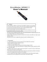
Fig 2: The DMC (Digital Mapping Camera) – an example of a digital aerial camera. Left: Camera mounted on carrier. Right: View from below – you can see the lenses belonging to the four
area sensors. Courtesy of Intergraph Corp., USA.
Furthermore, the lens system of aerial cameras is constructed as a unit with the
camera body. No lens change or “zoom” is possible to provide high stability and a
good lens correction. The focal length is fixed, and the cameras have a central
shutter.
1 Introduction
5
Similar to this, also for close-range applications special cameras were developed with a medium or large film format and fixed lenses.
Since long times, manufacturers like Z/I imaging (now Intergraph Corp.), Leica
or Vexcel have been developing digital aerial cameras. As we can see today, there
are two construction strategies. One is to keep the central perspective principle
well-known from existing film cameras with the advantage that you can use existing software to handle the data. For this solution (called frame camera), an area
sensor is required. Considering the fact that a high-resolution area sensor giving
the same information like 230 by 230 mm photos taken on film would be extremely expensive, efforts are made to use four overlapping smaller sensors of
industrial standard and then match the four image parts together (DMC from Intergraph, see figure 2). The other strategy is to use a line sensor across the flight
direction and collect data continually during the flight. This is a bit similar to the
techniques known from sensors on satellites or from hyper-spectral scanners (ADS
40 from Leica).
Fig. 3: Example of metric digital cameras: The medium-format AIC (left) and the small-scale d7
metric (right) from Rollei. Courtesy of Rollei Fototechnic, Germany.
For the close-range case the transition from film to digital cameras can be described in the way that existing film cameras are still in use, but if a new camera
shall be purchased it will be a digital one in any case. On the market are smallformat and medium-format cameras like those from Rollei (d7 metric, d30 metric
or the AIC, also well suitable for the aerial case, see figure 3).
Nowadays digital consumer cameras have reached a high technical standard
and good geometric resolution and are available for low prices. Due to the fact
that these cameras can be used for close-range photogrammetry without any problem if the accuracy to be reached is not too high, a separate chapter will deal with
this kind of equipment.
6
Digital Photogrammetry
1.4
Digital consumer cameras
As mentioned just before, various types of digital consumer cameras are on the
market which may also be used for photogrammetric applications. The differences
of the construction principles between metric and consumer cameras can be seen
in general in quality and stability of the camera body and the lens. Further, consumer cameras usually have a zoom (“vario”) lens with larger distortions which
are not constant but vary for instance with the focal length, so it is difficult to
correct them with the help of a calibration.
If you want to purchase a digital camera to use it for photogrammetry please
take the following remarks into account:
General: It should be possible to set the parameters focal length, focus, exposure time and f-number manually, at least as an option.
Resolution (Number of pixels): Decisive is the real (physical), not an interpolated resolution! The higher the number of pixels, the better – but not at any price:
Small chips with a large number of pixels of course have a very small pixel size
and are not very light sensitive, furthermore the signal-noise ratio is less good.
This you will find especially with higher ISO values (200 and more) and in dark
parts of the image.
Focal length range (zoom): Decisive is the optical, not the digital (interpolated)
range!
Distance setting (focus): It should be possible to de-activate the auto focus. If
the camera has a macro option you can use it also for small objects.
Exposure time, f-number: The maximum f-number (lens opening) should not be
less than 1:2.8, the exposure time should have a range of at least 1 ... 1/1000 seconds.
Image formats: The digital images are stored in a customary format like JPEG
or TIFF. Important: The image compression rate must be selectable or, even better, the compression can be switched off to minimise the loss of quality.
Storage: Usual are SD memory cards with capacities up to 4 GB. Modern PCs /
Laptops are supplied with SD card readers – this will save accumulator energy
when transferring data from the camera to the computer.
Energy supply: Make sure that you can use customary batteries or accumulators. They are much cheaper than special ones and available everywhere.
1 Introduction
7
Others: Sometimes useful are a tripod thread, a remote release and an adaptor
for an external flash. Two sets of accumulators, a battery charger, additional
memory cards, if need be a card reader and a good tripod complete the equipment.
A final remark: As everywhere in life, “cheap” is not always equal to “good”!
Therefore you should better proof the quality than the price…
To work with image data from a digital camera you need some information like
the focal length or the size of the pixels on the CCD chip. In the appendix you find
a table with technical data of several CCD chips, and in the tutorials 3 and 4 you
will see how to handle the images.
1.5
Short history of photogrammetric evaluation methods
In general, three main phases of photogrammetry can be distinguished concerning
the techniques of the equipment used for evaluation and the resulting workflow.
The transition from one phase to the following took a time of about 20 years or
even more.
In the chapter 1.1 you saw that, if we want to get three-dimensional co-ordinates of an object point, we must reconstruct the rays belonging to this point from
the terrain through the projection centres into the central perspective photos, a
procedure which we call reconstruction of the orientation or briefly orientation. In
the first decades of photogrammetry this was done in a pure optical-mechanical
way. The large, complicated and expensive instruments for this could only be handled with a lot of experience which led to the profession of a photogrammetric
operator. Not only the orientation of the photos but also any kind of the following
work like measuring, mapping and so on was carried out mechanically. In later
times, this phase was named the Analogue Photogrammetry.
With the upcoming of computers, the idea was to reconstruct the orientation no
more analogue but algorithmic – via formulas with their parameters (coefficients)
being calculated and stored in the computer. The equipment became significantly
smaller, cheaper and easier to handle, and was supplied with linear and rotation
impulse counters to register hardware co-ordinates, and with servo motors to provide the ability to position the photos directly by the computer. Nevertheless, the
work still was done with real (analogue) photos and still needed a high precision
mechanical and optical piece of equipment, the so-called analytical plotter. According to that, this phase was called Analytical Photogrammetry.
As everybody knows, in the last decades the power of computers rose at breathtaking speed. So, why not use digital photos and do the work directly with the
computer? Even a simple PC nowadays has power and storage capacity enough to
handle high-resolution digital photos. That is the phase now: Digital Photogrammetry, and that’s what we want to explain with the help of this book, the included
8
Digital Photogrammetry
software and some examples. The only remaining analogue part in the chain of a
total digital workflow often are the photos themselves when taken with traditional
cameras on film, but also this will end soon.
For existing photos on film or paper, we will need a high-precision scanner as
the only special hardware periphery. And due to the fact that around the world
hundreds of “classical” aerial cameras are in use – instruments with a lifetime of
decades – and digital cameras are much more expensive up to now, photo production on film with subsequent scanning may be the standard for many years
(MAYR 2002). On the other hand we must recognise that a totally digital workflow has much advantages and is much faster, and no film development is necessary, a fact which significantly decreases the costs.
1.6
Geometric principles 1: Camera position, focal length
To explain the relation between the distance camera position – object (aerial case:
flying height) and the focal length, we use a terrestrial example. First, take a look
at figure 4:
Our goal is to take a photo of the house, filling the complete image area. We
have several possibilities to do that: We can take the photo from a short distance
with a wide-angle lens (like camera position 1 in the figure), or from a far distance
with a small-angle lens (telephoto, like camera position 2), or from any position in
between or outside. Obviously, each time we will get the same result. Really?
Figure 5 shows the differences. Let’s summarise them:
•
The smaller the distance camera – object and the wider the lens angle, the
greater are the displacements due to the central perspective, or, vice versa:
•
The greater the distance camera – object and the smaller the lens angle, the
smaller are the displacements.
In a (theoretical) extreme case, if the camera could be as far as possible away from
the object and if the angle would be as small as possible (“super telephoto”), the
projection rays would be nearly parallel, and the displacements near to zero. This
is similar to the situation of images taken by a satellite orbiting some hundreds of
kilometres above ground, were we have nearly parallel projection rays but also
influences coming from the earth curvature. The opposite extreme case are photos
taken with a fisheye lens which have an opening angle of up to 180 degrees, sometimes called whole-sky-systems.
1 Introduction
9
Our house,
view from top
camera position 1
camera position 2
Fig. 4: Different positions and lens angles. The situation, view from above.
What are the consequences? If we would like to transform a single aerial image
to a given map projection, it would be the best to take the image from as high as
possible to have the lowest displacements – a situation similar to satellite images
(see above). On the other hand, the radial-symmetric displacements are a prerequisite to view and measure image pairs stereoscopically as you will see in the
following chapters, and therefore most of the aerial as well as terrestrial photos
you will use in practise are taken with a wide-angle camera, showing relatively
high relief-depending displacements.
10
Digital Photogrammetry
Photo taken from camera position 1
Photo taken from camera position 2
Photo taken from a position infinitely far away
Fig. 5: The results: Photos showing the house in same size but in different representations due to
the central perspective.
1 Introduction
11
1.7
Geometric principles 2: Image orientation
As already mentioned before, the first step of our work will be the reconstruction
of the orientation of each photo, which means that we have to define the exact
position of all photos which we want to use within the object (terrain) co-ordinate
system. Now please imagine the following: If we know the co-ordinates of the
projection centre, the three rotation angles (against the x-, y- and z-axis) as well as
the focal length of the camera (part of the interior orientation, see chapter 4.2.2),
then the position of the photo is unequivocally defined (see figure 6). Therefore
our first goal will be to get the six parameters of the exterior orientation (x0, y0, z0,
ϕ, ω, κ; see chapter 4.2.5).
In the case of aerial photos, the values of ϕ (phi) and ω (omega) will normally
be near to zero. If they are exactly zero, we have a so-called nadir photo. But in
practice, this will never happen due to wind drift and small movements of the
aircraft. Always remember the rule “nothing is exact in real life”! The value of κ
(kappa) is defined as “east = zero” according to the x-axis of the terrain co-ordinate system, then counting anti-clockwise in grads, defining north = 100, west =
200, south = 300 grads (see chapter 1.10 for the units).
Please note that only exact nadir photos of a true horizontal plane would have a
unique scale or, in other words, non-zero values of ϕ and/or ω as well as the form
of the object (for instance the relief) lead to scale variations within the photo.
If Mb is the mean photo scale or mb the mean photo scale number, hg the height
of the projection centre above ground and f the focal length, we can use the following formulas (see figure 7):
mb = hg/f
or
Mb = 1/mb = f/hg
1.7.1
Now take a look at the different co-ordinate systems (CS) which we have to
deal with. First, the camera itself has a two-dimensional CS; this may be a traditional or a digital one (image CS). Second, in case of film or paper material we
must use a scanner which has a two-dimensional pixel matrix (pixel CS) – the
equivalent to the photo carrier co-ordinates of an analytical plotter (see chapter
1.5). And finally our results should be in a three-dimensional object (terrain) CS –
normally a rectangle system like used for the Gauss-Krueger or the related UTM
projection, connected with an ellipsoid to define the elevation (for instance, in
Germany the Gauss-Krueger system is related with the Bessel ellipsoid, the UTM
system with the ellipsoid defined from Hayford).
12
Digital Photogrammetry
film or CCD chip
principal point
focal length f
projection centre
(x0, y0, z0)
z
κ (kappa)
0 = East
y
ϕ (phi)
phi, omega:
0 = horizontal
ω (omega)
x
rotation angles (ϕ, ω, κ)
Fig. 6: Focal length, projection centre and rotation angles
As we will see later on, the values of the three rotation angles depend on the
sequence in which they were calculated. Often used are the sequences ϕ, ω, κ and
ω, ϕ, κ – most software packages have the option to convert the angle values
between these sequences.
1 Introduction
x‘
13
photo
f
projection
centre
opening
angle
hg
ground
x
Fig. 7: Relations between focal length f, height above ground hg and the photo scale f/hg
1.8
Geometric principles 3: Relative camera positions
(stereo)
To get three-dimensional co-ordinates of object points we need at least two images
from our object, taken from different positions, as we already said in chapter 1.1.
This leads to the question which rules we must fulfil concerning the relative camera positions.
Remember figure 1: The point P (x, y, z) will be calculated as an intersection of
the two rays [P'
P] and [P''
P]. You can easily imagine that the accuracy of
the result depend among others from the angle between both rays. The smaller this
angle, the less will be the accuracy: Take into account that every measurement of
the image points P' and P'' will have more or less small errors, and even very small
errors here will lead to a large error especially in z when the angle is very small.
Besides, this is a further reason why wide-angle cameras are preferred in photogrammetry (see next figure).