Calibration of CNC milling machine by direct metho
Bạn đang xem bản rút gọn của tài liệu. Xem và tải ngay bản đầy đủ của tài liệu tại đây (631.15 KB, 11 trang )
Seediscussions,stats,andauthorprofilesforthispublicationat: />
CalibrationofCNCmillingmachinebydirect
method
ArticleinProceedingsofSPIE-TheInternationalSocietyforOpticalEngineering·December2008
DOI:10.1117/12.807066
CITATION
READS
1
254
2authors,including:
WuyiChen
BeihangUniversity(BUAA)
118PUBLICATIONS633CITATIONS
SEEPROFILE
AllcontentfollowingthispagewasuploadedbyWuyiChenon21May2015.
Theuserhasrequestedenhancementofthedownloadedfile.Allin-textreferencesunderlinedinblueareaddedtotheoriginaldocument
andarelinkedtopublicationsonResearchGate,lettingyouaccessandreadthemimmediately.
Calibration of CNC milling machine by direct method
Abdul Wahid Khan*, Wuyi Chen **
School of Mechanical Engineering and Automation, Beihang University
Beijing 100083, China.
ABSTRACT
Calibration refers to the system of quantity value determination of instruments, equipments and test devices according to
industrial requirement, based on metrological characteristics. In present research critical parameter which affects the
accuracy and product quality of a CNC milling machine, was investigated and quantified by using direct method. These
parameters consist of position dependent or position independent parameters, like linear displacement errors, angular
errors of linear axes, straightness error of linear axes and squareness error between the axes. Repeatability, lead screw
and resolution error of the CNC milling machine were also quantified to provide additional information to the user,
because in absence of this additional information a misconception persists causing a major contributor to the inaccuracy
and quality of the product. Parameters were measured and quantified by using a laser interferometer and artifacts as
working standards under controlled environmental conditions on a manufacturing CNC milling machine. Polynomial
regression analyses were carried out for finding the coefficients to predict the errors at each and every desired position
which is quite useful for compensation and enhancing the accuracy of a machine system. Machine accuracy detailed
chart was also made to assess and assure the accuracy, capability or for accuracy monitoring of the CNC milling machine
Key words: Error characterization, Calibration, Laser interferometer, Measurement method, Quality control, Metrology
1. INTRODUCTION
Calibration is defined as set of operations which establish, under specified conditions, the relationship between values of
quantities indicated by a measuring instrument or measuring system, or values represented by a material measure or a
reference material, and the corresponding values realized by standards [1]. It determines the relation between the output
of the machine tool, instrument or test device and the value of the input quantity, attribute or measurement standard.
Calibration is the only comprehensive indicator which depicts a detailed picture regarding accuracy of machine tools
which is one of the most important indices to assess the quality and capability of machine tools. Accuracy parameter
significantly affects all criterion of machine performance including quick acting, energy efficiency, metal consumption,
reliability and durability. On basis of calibration results a qualification or capabilities are ascertained to permit the
machine tool, for further processing of compatible accuracy requirement. The results of calibration make possible either
the assignment of values of measurand to the indications or the determination of corrections with respect to indications
[2]. Calibration of machine tools is important for both acceptance testing and error characterization and for compensation
etc. [3-7]. Basically there are only three common methods reported [8] which are well known and in practice for
calibration of machine tools. The first method is direct or parametric method and quite popular for quantifying various
error terms independently. Second method is known as volumetric calibration method and able to quantify the error
between actual and commanded motion at specific desired point in workspace of a machine tool. It uses some sort of
kinematic reference standards such as double ball bar, disk etc. and mostly used for acceptance testing and for the
periodic checks. Third method is based on measuring an artifact or standard part, such as ball plate, cubic box,
tetrahedron etc. and known as artifact calibration method or hybrid calibration method. This method is also applicable
for acceptance testing and periodic checks. The parametric method is the only well known method which is reliable and
provide realistic information about elemental accuracy of machine tools and most popular and appreciated by the
machine tool builders and the users for error characterization and error compensation. So in current research authors
implemented the parametric method on a CNC milling machine for error characterization in which 21 parametric
position dependent and position independent errors of CNC milling machine were quantified and besides these the
repeatability, resolution and lead screw errors were also assessed as an additional information. Authors tried to pay
attention to calibrate manufacturing machines which is rare attended before in manufacturing environment history
* ; **
2008 International Conference on Optical Instruments and Technology: Optoelectronic Measurement Technology
and Applications, edited by Shenghua Ye, Guangjun Zhang, Jun Ni, Proc. of SPIE Vol. 7160
716010 · © 2009 SPIE · CCC code: 0277-786X/09/$18 · doi: 10.1117/12.807066
Proc. of SPIE Vol. 7160 716010-1
although calibration is very common in metrological machines and metrological machines calibrated periodically .
2. OVERVIEW OF MACHINE TOOLS ERRORS
Errors in machine tools originate from various sources and causes degradation of machine tool accuracy whereas
accuracy is the only main metrological characteristics of machine tools which can be defined as the closeness of the
agreement between the results of a measurement and a true value of the measurand [1]. As the closeness of agreement
spread out the error enlarged and show the degradation of machine tool However degradation of accuracy means
degradation of product quality. For characterizing or improving the machine tool accuracy it is essential that one must
familiar with the sources which seriously effect and originates errors.
2.1 Errors and their sources in machine tools.
According to the nature of the machine tools errors can be divided into two main categories that are quasi-static and
dynamic errors. Quasi-static error which is the major sources of error in machine tools consists of geometric error,
kinematic error, stiffness error and thermal error. The quasi-static errors are considered as a major source of error and
contribute as much as 70% of the total machine errors [9]. Geometric error is introduced due to imperfection or
imprecision of structural elements and components used in assemblies or subassembly level whereas kinematic error is
introduced by the motion of the rigid bodies to reach the exact desired position. Geometric and kinematic errors are
considered as interrelated errors. Stiffness error is introduced due to lack of stiffness of machine bodies or having some
extent of elastic behavior under loading and unloading conditions. Thermal errors are mainly the major cause of
dimensional errors having a non linear behavior and due to its non linear behavior it is quite difficult to estimate exactly.
Dynamic errors originated from spindle motion, vibration affecting the machine structure and itself vibration in internal
components of machine tools and controller errors fall in this category. Besides these main errors there is some other
errors including cutting force induced errors, tool wear errors and fixturing errors.
2.2 Errors categorized on Position basis.
As quasi-static error contributes as a major source of error in a machine tool which can be minimized at its design stage
and improvement of the system carried out through some preventive actions or compensation etc, so main concentration
of the researcher is on this field in which errors can be quantified and avoided by taking preventive actions and
improving the flaws at design stages and processing stage. Abbaszadeh-Mir et al. [10] classified the rigid body geometric
errors in to two groups. The first group was the position independent geometric errors which were also called link errors
such as misalignments, angular offsets and position distance between rotary axes. The second group was the position
dependent geometric error parameters that varied with the position of the machine slides. Position independent errors can
be calculated by below given equation (1).
E = 3(n − 2)
(1)
“E” represents the error and “n” represents the number of joints
Whereas the total position dependent errors in a machine tool can be calculated by the formula given below
E = 6n
(2)
“E” represents the error and “n” represents the number of joints
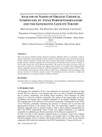
3. TOPOLOGY OF CNC MILLING MACHINE AND ERRORS IDENTIFICATION
A CNC milling machine as mentioned in figure-1 consists of three prismatic joints named as X, Y and Z slides oriented
and move along the X, Y and Z global coordinate system respectively. Y slide joins with the base of the CNC milling
machine and X-slide which accommodates the workpiece rides on the Y-slide. Z-slide directly joins with the base of
Proc. of SPIE Vol. 7160 716010-2
CNC milling machine and move along the global Z-coordinate system while carrying the spindle motor which mounted
on the Z-slide. When the machine coordinate is set at reference zero position all slides reference coincide to zero and
display X, Y and Z at zero position. According to the equation (2) the machine has total 18 dependent errors whereas the
total independent position errors which are calculated as per equation (1) are found 3. Prismatic joints X, Y and Z slides
fall in the category of rigid body system which has six degree of freedom in the space. When a prismatic joint moves, it
may have six degree of errors from aforesaid error causes. 6-DOF errors in a prismatic joint are composed of the three
along the axis X, Y, Z denoted by δ x , δ y , δ z and the three around the X, Y, Z axis called roll, pitch and yaw errors
εx , εy , εz
respectively. It can be presented and observed by the coordinate frames by appointing the reference frame
on the guide ways and appointing the moving frame on the slides. The translational and rotational errors can be observed
in the moving frame through the relative movement of reference frame elaborated in figure-2 and mentioned in Table-1.
Fig. 1. Topology of CNC milling machine
öz (x)
Fig. 2. 6DOF errors in a prismatic joint
Proc. of SPIE Vol. 7160 716010-3
Table-1 Error description in CNC milling machine
S.No
1
2
3
4
5
6
7
Error type
Linear displacement errors
Vertical straightness errors
Horizontal straightness errors
Roll angular errors
Pitch angular errors
Yaw angular errors
Squareness errors
Notation
δx(x), δy(y), and δz(z)
δy(x), δx(y), and δx(z)
δz(x), δz(y), and δy(z)
εx(x), εy(y), and εz(z)
εy(x), εx(y), and εx(z)
εz(x), εz(y), and εy(z)
Sxy, Syz, Szx
where, “δ” is the linear error, subscript is the error direction and the position coordinate is inside the parenthesis, “ε” is
the angular error, subscript is the axis of rotation and the position coordinate is inside the parenthesis.
4. CALIBRATION THROUGH DIRECT METHOD
Direct calibration method or error quantification is carried out at elemental basis and total positions dependent and
position independent parameters can be measured and quantified individually. This approach addresses the problem of
computing deformation of machine members individually because the errors meterage of these parameters is usually
impossible to analyze precisely by using some other techniques or methodology and quantification of elemental errors is
the only possible solution which helps out to find the genuine major source, causes and their contribution in accuracy of
machine tool. In direct calibration technique, the structure of the machine is considered as a kinematical model and is
then analyzed using the rigid body kinematics so each error can be measured through conventional or by using available
modern equipment such as laser interferometer, its accessories and electronic level etc. as described by Weck and
Bibring [11] and by Sarotori and Zhang [12]. Table-2 lists suitable methodology choice. Similar measurement guide line
and help are available in some standards documents like ASME B.89.1 and ISO10360 standards [13, 14]. Direct method
is considered quite useful for error elimination, minimization through adjustment or compensation. The main advantage
of this method is that it presents the direct verification and evidences of mechanical accuracy of a machine tool or its
prismatic joints and considered as an authentic method to provide error diagnosis or compensation
Table-2 Measuring methods for determining parametric errors of CMMs
Errors
Positional Errors
Straightness error
Pitch and yaw errors
Roll Errors
Squareness errors
Measurement Equipment or Methodology
Laser interferometer, Step gauge, and Gauge blocks, end bars, ball arrays.
Straightness interferometer, Mechanical and optical straight edge,
Alignment telescope with target, Alignment laser. Displacement indicator or
sensors, taut wire etc.
Differential interferometer, Mechanical and Electronic level,
Autocollimator, Measurement of positional error along lines with different
Abbe’s offset. Angular laser interferometer.
Electronic levels, Reference Flat, Measurement of straightness errors of two
parallel lines.
Optical and Mechanical Squareness standard, Length standard inclined
under defined angles. Diagonal measurements.
Proc. of SPIE Vol. 7160 716010-4
5. CALIBRATION OF CNC MILLING MACHINE BY USING DIRECT METHOD
Calibration of a CNC milling machine (model XK7132) was carried out by using direct calibration method in which 21
parametric errors were measured directly. The CNC milling machine was equipped with a Fanuc controller. The stroke
ranges were X=500mm, Y= 300mm and Z=350mm with resolution of 1µm, position accuracy 10µm and repeatability
7µm. For direct calibration a laser interferometer of Renishaw ML-10 along with optics and accessories was adopted as a
work standard, which was featured with HeNe laser beam with nominal wave length 0.633 µm (in vacuum), and the long
term wavelength stability was better than 0.1ppm. EC-10 environmental compensation unit for air temperature and air
humidity compensation, and interfacing card along with data logging and evaluating software were also used.
Experiment was carried out under controlled environmental conditions to minimize the effects of random errors and to
get the reliable results since the measurement is sensitive by operating temperature and its gradient. Material temperature
sensors and air temperature sensor were mounted to avoid temperature effect on measurement process. Three prismatic
joints X, Y and Z slides of the machine were calibrated as shown in figure-3 and in figure-4.
-I
Fig. 3. Straightness measurement by using laser interferometer
Fig. 4 Displacement error measurement through laser interferometer
Proc. of SPIE Vol. 7160 716010-5
Laser interferometer was used as per standard operating procedure and available guide lines mentioned in the operating
instruction manual. Instrument was preheated according the instructions and tried to shorten the distance between laser
head and laser interferometer so that measuring errors could be minimized. Optics was aligned in good manners and
measurement was taken when properly aligned and more than 95% signal strength was displayed on screen over the
entire axis travel during the measurement because the better alignment prevented dead path and cosine errors. To obtain
accurate and precise results the laser interferometer results were corrected for air temperature, air humidity and air
pressure to prevent thermal shock erroneous effect on wavelength of laser beam. Linear displacement accuracy,
straightness error and pitch and yaw errors were measured in X, Y, Z direction by using the Laser interferometer. Five
ascending and descending readings were taken by using sequential displacement method. Remaining errors were
measured by using artifacts such as squareness measured through standard granite square by using reversal method, see
figure-5. Roll can be measured through electronic level. For measuring the squareness error standard granite square in
conjunction with sensors was used as Mechanical Square. It was placed in an axial plane approximately aligned with two
axial directions. Squareness measurement was carried out by using reversal method as mentioned as in figure-3. The 21
parametric errors of CNC milling machine including 3 displacement errors, 6 straightness errors, 9 angular errors and 3
squareness errors were measured by the aforesaid methods and results are shown through graph in figure 6-12 Resolution
of the CNC milling machine, repeatability and lead screw errors were also measured. Resolution results were shown
through figure-13 and lead screw error was exhibited through figure-14.
α
α
Fig.5. Measurement by reversal method (Red dot show the measuring sensor and colored lines indicates the measurement sides)
Displace me nt Vs Translational Error
Displace me nt Vs Straightne ss Error along
X-Axis
50
60
40
20
0
- 20 0
30 60 90 120 150 180 210 240 270 300
- 40
δ y( Y)
40
30
20
10
0
0
Displace me nt (mm)
δ x( X)
Error (micron)
Error (micron)
80
40
80
120 160 200 240 280
Di spl acement ( mm)
δ z( Z)
Fig. 6 Displacement Vs Translational Error
δ y( X)
δ z( X)
Fig.7 Displacement Vs Straightness Error X-direction
Proc. of SPIE Vol. 7160 716010-6
Displace me nt Vs Straightne ss Error along
Z-Axis
300
Error (micron)
Error (micron)
Dispalce me nt Vs Straightne ss Error along YAxis
200
100
0
0
20 40 60 80 100 120 140 160 180 200
Displace me nt (mm)
δ x( Y)
30
60
90 120 150 180 210 240
δ y( Z)
Fig.9 Displacement Vs Straightness Error Z direction
Displace me nt Vs Angular Errors along Y-Axis
1. 5
Error (rad)
0. 1
12
0
15
0
18
0
21
0
24
0
27
0
30
0
90
60
30
0
0
0
- 50
δ x( Z)
0. 2
Error (rad)
0
δ z( Y)
Displace me nt Vs Angular Errors along X-Axis
- 0. 2
50
Displace me nt (mm)
Fig. 8 Displacement Vs Straightness Error Y-direction
- 0. 1
100
Displace me nt (mm)
ε y(X)
0. 5
0
- 0. 5 0
- 0. 3
ε x(X)
1
30
60
90
ε x(Y)
Fig. 10 Displacement Vs Angular Error in X-direction
180
0. 4
0. 35
0. 3
0. 25
0. 2
0. 15
0. 1
0. 05
0
30
ε y(Y)
ε z(Y)
Fig.11 Displacement Vs Angular Error in Y-direction
Displace me nt Vs Angular Errors along Z-Axis
Error (rad)
150
Dispalce me nt (mm)
ε z(X)
- 0. 05 0
- 0. 1
120
60
90
120
150 180
210 240
Displace me nt (mm)
ε x(Z)
ε y(Z)
ε z(Z)
Fig.12 Displacement Vs Angular Error in Z-direction
Proc. of SPIE Vol. 7160 716010-7
rim.
- All Data Plot: RESOLUTION X-O.O1 -0225-400.RTL
ALL tATA PWI'
4
3.5
a
2.5
C
IJ
0.5
11 Dta F1t -0Line'00'
0.002
0.003
0.004
0.005
0.007
0.006
T
aii11i)
Macbina
Serial Nc.
at ion:
Date1135 Feb 25 2008
ename: RESOLUTION X-0
irect ional
Fig. 13. Resolution results
All Data Plot: PITCH-X-SCREW-1 8-06.RTL
LJ. FT Fiø1'
0.
0
.0.
.1
.1
.2
.2.
.3
Plot
Serial No:
10
f ta
Machine:
i
Date:16:02 Feb 23 2008
By:
12
TJtt (nilliurt)
18
:
Location:
°i lenae PTICM-X-SCREWBid ireot ional
Fig. 14. Lead Screw errors
5. MEASUREMENT RESULTS AND DISCUSSION
Three prismatic joints X, Y and Z slides of the CNC milling machine was calibrated and quantified by using the laser
interferometer along with its optics and standard accessories and by using standard artifacts. The specification are
already discussed in this paper however these joints were measured a little less to their effective ranges to get the true
pictures of errors and to avoid the backlash etc. X-prismatic joint was measured in the range of 300 mm; Y-Prismatic
joint was measured in the range of 200mm whereas Z-Prismatic joint was measured up to 250 mm of its working range.
Measurements were taken under controlled environment and in a cold state temperature gradient compensation was also
Proc. of SPIE Vol. 7160 716010-8
made in the observed results. This machine was in use from last eight years and it was not calibrated so that its accuracy
was a big question. To ensure its accuracy and reliability calibration process was carried out for its error mapping. Large
errors were observed in the translation, horizontal and vertical straightness of each prismatic joint whereas the pitch, roll
and yaw was observed very small. Among the prismatic joints the mostly biggest errors were observed in horizontal
straightness of X-Prismatic joint and similar vertical straightness observed high in Y-Prismatic joint due to joint
excessive usage. Detailed results against three prismatic joints and error mapping graphs were plotted to predict the
errors at each and every desired position which is quite useful for compensation and enhancing the accuracy of a
machine system. Resolution of CNC milling machine, repeatability and lead screw errors were also measured to provide
additional information to the user so that user must be well informed and aware about the machine tool accuracy.
Machine accuracy detailed chart was also made to assess and assure the accuracy, capability or for accuracy monitoring
of the CNC milling machine to give the quick out look of errors in prismatic joints attached as Appendix-A at the end of
this paper.
6. SUMMARY AND CONCLUSION
In this paper an attempt has been made by the authors to calibrate the CNC milling machine by implementing the direct
method for error quantification of 21 position dependent and position independent parameters. This method was quite
reliable, authentic and simple for measuring the parametric errors. Direct measuring method is a well established
methodology in which a laser interferometer mostly used as a metrology tool for measurement of positioning errors,
straightness errors and squareness error with high accuracy and reliability. The only disadvantage of this method was that
it took a long time for the error measurement and error analysis. But this disadvantage is nothing in comparison of its
reliable and authenticated results on which adjustment and compensation of the machine based for maintaining its
accuracy. It is extremely helpful for the machine tool builders and the machine tool users. Machine resolution was not
the same as claimed by the manufacturer due to its controller lead and lag movement. Repeatability was found
unsatisfactory and error in lead screw was also observed which need compensation.
REFERENCES
1.
2.
3.
4.
5.
6.
7.
8.
9.
10.
11.
12.
13.
14.
International Vocabulary of Basic and General Terms in Metrology, BIPM, IEC, IFCC, ISO, IUPAC, IUPAP,
OIML, 1993.
Placko Dominique, Metrology in Industry: The key for quality Edited by French college of Metrology pp.128, 2006,.
R. Hocken, “Machine tool Accuracy,” Technol. machine tools, l5 Lawrence Livermore National Laboratory,
University of California, Report of the machine tool task force , UGRL-52960-5, pp. 1-85. (1980).
J. Tlusty, “Testing of accuracy of machine tools”, Report No. UGRL-52960-Supp. 1, 1980.
G. Zhang et al. "Error compensation of coordinate measuring machines,” Ann. CIRP, 34(1), (1985).
R. Hocken et al. “Three dimensional metrology” Ann. CIRP. 26(2), (1977).
A. Donmez et al., “A general methodology for machine tool accuracy enhancement by error compensation,” Prec.
Engg. 8 (4), (1986).
G. Zhang, R. Ouyang, B. Lu, R. Hocken, R. Veale, A. Donmez, “ A displacement method for machine geometry
calibration,” Ann. CIRP 37(1), (1988).
J. B. Bryan, Ann. CIRP 39(2). 645-656, (1990).
Y. Abbaszadeh-Mir., J.R. R. Mayer, G. Cloutier, C. Fortin, "Theory and simulation for the identification of the link
geometric errors for a five-axis machine tool using a telescoping magnetic ball bar," Int. J. Prod. Res. 40 (18),
4781-4791 (2002)
M. Weck, and H. Bibring, Handbook of Machine tools: Metrological analysis and performance tests, Volume 4,
John Willey and sons, 1984.
S. Sarotori,. and G.X. Zhang, “Geometric error measurement and compensation of machines” Ann. CIRP 44(2), 599609 (1995).
“Methods for Performance Evaluation of coordinate measuring machines,” ANSI / ASME B89.1.12M-1990 by the
American Society of Mechanical Engineering, 1990.
ISO 10360: 2000, Geometrical Product Specifications (GPS). Acceptance and reverification tests for coordinate
measuring machines, an International organization for standardization, 2002.
Proc. of SPIE Vol. 7160 716010-9
Appendix-A:
CNC machine tool accuracy chart
S.No
Error type
1
Linear displacement errors
2
Vertical straightness errors
3
Horizontal straightness errors
4
Roll angular errors
5
Pitch angular errors
6
Yaw angular errors
7
Squareness errors
8
Repeatability
9
Resolution Error
10
Lead screw pitch error
Notation
Quantified Max eror
δx(x)
δy(y)
δz(z)
δy(x)
δx(y)
δx(z)
δz(x)
δz(y)
δy(z)
εx(x)
εy(y)
εz(z)
εy(x)
εx(y)
εx(z)
εz(x)
εz(y)
εy(z)
Sxy
Syz
Szx
X slide
Y slide
Z slide
X slide
Y slide
Z slide
X , Y, and Z
lead screw
-10.5805 ~ -33.3935 µm
-4.8702 ~ -12.0613 µm
-0.0085 ~ -0.0683 µm
12.4833 ~ 44.9643 µm
21.504 ~ 44.7607 µm
-2.1882 ~ -16.8187 µm
6.3403 ~ 19.1099 µm
85.9738 ~ 201.4288 µm
8.599 ~ 68.7925 µm
-0.0471 ~ -0.01696 rad
0.016 ~ 0.0351 rad
-0.0085 ~ -0.0683 rad
-0.0761 ~ -0.1855 rad
0.5652 ~ 1.3997 rad
0.0437 ~ 0.03493 rad
0.0461 ~ 0.1662 rad
-0.1273 ~ -0.3152 rad
0.0035 ~ 0.0587 rad
-1.0369 degree
-0.0055 degree
-0.0055 degree
4.607 µm
18.156 µm
11.051 µm
-0.1 ~3.4 µm
0.1 ~ 4 µm
-0.2 ~2 µm
Proc. of SPIE Vol. 7160 716010-10
View publication stats
2 ~ 4.322 µm