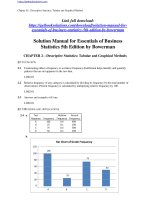
Solution manual for design of fluid thermal systems SI edition 4th edition by janna
Bạn đang xem bản rút gọn của tài liệu. Xem và tải ngay bản đầy đủ của tài liệu tại đây (2.23 MB, 33 trang )
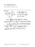
Chapter 2
Download Solution Manual for Design of Fluid Thermal Systems SI Edition 4th Edition by
Janna
/>
Density, Specific Gravity, Specific Weight
◦
1. What is the specific gravity of 38 API oil?
◦
141.5
38 API oil sp.gr. =
= 141.5
131.5
API
131.5
◦
+
141.5
sp. gr. = 169.5 = 0.835
38
+
◦
2. The specific gravity of manometer gage oil is 0.826. What is its density and its API rating?
3
sp. gr. = 0.826; ρ = 1000(0.826) = 826 kg/m
3
ρ = 62.4(0.826) = 51.54 lbm/ft
sp. gr. =
◦
◦
131.5 + API = 141.5
141.5
131.5
API
0.826
◦
+
−
=
API
171.3
;
131.5
◦
=
API
◦
39.8 API
≈
◦
40 API
◦
◦
3. What is the difference in density between a 50 API oil and a 40 API oil?
141.5
141.5
◦
sp. gr. = 131.5
API = 131.5 50 = 0.7796 for a 50 oil
+◦
+
141.5
141.5
◦
sp. gr. = 131.5 API = 131.5 40 = 0.826 for a 40 oil
◦
+
+
0.825 − 0.7796 = 0.0455 density difference
◦
2
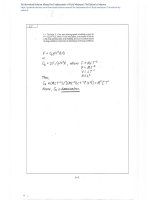
4. A 35 API oil has a viscosity of 0.825 N·s/m . Express its viscosity in Saybolt Universal Seconds
(SUS).
141.5
◦
35 AFI oil sp. gr. = 131.5
◦API
+
2
μ = 0.825 N·s/m
ν = μgc
ρ
141.5
= 131.5 35 = 0.850
+
−4
0.825
= 10 × 10
=
0.850(1000)
Highly viscous; try
ν = 0.2158 × 10
−6
10 × 10
SUS =
(SUS)
−4
0.2158 × 10⁻⁶
if SUS > 215
=
4633 SUS
c 2015 Cengage Learning. All Rights Reserved. May not be scanned, copied or duplicated, or posted
to a publicly accessible website, in whole or in part.
2-1
3
5. Air is collected in a 1.2 m container and weighed using a balance as indicated in Figure P2.5. On
3
◦
the other end of the balance arm is 1.2 m of CO2. The air and the CO2 are at 27 C and atmospheric
pressure. What is the difference in weight between these two volumes?
CO2
air
FIGURE P2.5.
◦
3
Air at 27 C = 300 K has ρ = 1.177 kg/m
◦
3
CO2 at 27 C = 300 K has ρ = 1.797 kg/m
3
For a volume of 1.2 m , the weight of air is
3
3
2
(1.177 kg/m )(1.2 m )(9.81 m/s ) = 13.86 N
For CO2
3
3
2
(1.797 kg/m )(1.2 m )(9.81 m/s ) = 21.15 N
Weight difference is 21.15 − 13.86 = 7.29N
6. A container of castor oil is used to measure the density of a solid. The solid is cubical in shape, 30
mm × 30 mm × 30 mm, and weighs 9 N in air. While submerged, the object weighs 7 N. What is the
density of the liquid?
3
Castor Oil ρ = 960 kg/m
buoyant force
volume
=
ρ
mg
in air
− mg
submerged
= ρg
V
9−7 1
3
7 551 kg/m
3
= (0.03) 9.81 =
7. A brass cylinder (Sp. Gr. = 8.5) has a diameter of 25.4 mm and a length of 101.6 mm. It is submerged
in a liquid of unknown density, as indicated in Figure P2.7. While submerged, the weight of the
cylinder is measured as 3.56 N. Determine the density of the liquid.
weight
FIGURE P2.7.
submerged
object
Buoyant force = mgin air − mgsubmerged = mg − 0.8
2
mg − 0.8 ρg V π D h
buoyant force
π (0.0254)2(0.1016) 5.15 10
volume
=
V
=
= 4 = 4
=
×
−5
mg = ρbV g = 8500(5.15 × 10 )(9.81) = 4.29 N
mg − 0.8
4.29 − 3.56
ρ
×
=
= 9.81(5.15
3
ρ = 1454 kg/m
gV
3
5m
−
−
5
10 )
c 2015 Cengage Learning. All Rights Reserved. May not be scanned, copied or duplicated, or posted
to a publicly accessible website, in whole or in part.
2-2
Viscosity
8. Actual tests on Vaseline yielded the following data:
2
τ in N/m
0 200
600 1 000
d V /d y in 1/s 0 500 1 000 1 200
Determine the fluid type and the proper descriptive equation.
1200
shear stress
1000
800
600
400
200
0
0
τ=K
dV
500
1000
strain rate
1500
n
dy
Can be done instantly with spreadsheet; hand calculations follow for comparison purposes:
dV/dy
0
500
1000
1200
Sum
ln(dV/dy)
—
6.215
6.908
7.090
20.21
ln τ
—
5.298
6.397
6.908
18.60
τ
0
200
600
1000
ln(τ)· ln(dV/dy)
·
32.93
44.19
48.98
126.1
2
m = 3 Summation (ln(dV/dy)) = 136.6
b
1=
3(126.1) − 20.21(18.60)
3(136.6)
20.212
=
1.766
−
20.21
18.60
b0 =
3 − 1.766
3 = −5.697
K = exp(b0) = 0.00336;
dV
τ = τo + K
dy
n
n = b1 = 1.766
dV
1.766
= 0.00336 dy
c 2015 Cengage Learning. All Rights Reserved. May not be scanned, copied or duplicated, or posted
to a publicly accessible website, in whole or in part.
2-3
9. A popular mayonnaise is tested with a viscometer and the following data were obtained:
2
τ in g/cm
40 100 140 180
d V /d y in rev/s
0
3
7 15
Determine the fluid type and the proper descriptive equation.
The topmost line is the given data, but to curve fit, we subtract 40 from all shear stress readings.
200
180
stress
160
140
120
she
ar
100
80
60
40
20
0
0
5
10
15
20
strain rate
dV
dV
n
n
which becomes τ = τ − τo = K dy
τ = τo + K dy
Can be done instantly with spreadsheet; hand calculations:
dV/dy
0
3
7
15
Sum
τ
τ
40
0
100
60
140 100
180 140
ln(dV/dy)
—
1.099
1.946
2.708
5.753
ln τ
—
4.094
4.605
4.942
13.64
ln(τ )· ln(dV/dy)
—
4.499
8.961
13.38
26.84
2
m = 3 Summation (ln(dV/dy)) = 12.33
3(26.84) − 5.753(13.64)
b
1=
3(12.33)
5.7532
−
13.64
5.753
b0 =
3 − 0.526 3
K = exp(b0) = 34.37;
dV
τ = τo + K dy
=
0.526
= 3.537
n = b1 = 0.526
dV
n
=
0.526
40 + 34.37 dy
2
where dV/dy is in rev/s and τ in g/cm ; these are not standard units.
c 2015 Cengage Learning. All Rights Reserved. May not be scanned, copied or duplicated, or posted
to a publicly accessible website, in whole or in part.
2-4
10. A cod-liver oil emulsion is tested with a viscometer and the following data were obtained:
τ in
d V /d y in rev/s
0
0
40
0.5
60
1.7
80 120
3
6
Graph the data and determine the fluid type. Derive the descriptive equation.
Cod liver oil; graph excludes the first data point.
140
shear
stress
120
100
80
60
40
20
0
0
2
4
strain
dV
6
8
rate
n
τ = K dy
Can be done instantly with spreadsheet; hand calculations:
dV/dy
0.5
1.7
3
6
Sum
ln(dV/dy)
−0.6931
0.5306
1.099
1.792
2.729
τ
40
60
80
120
ln τ
3.689
4.094
4.382
4.787
16.95
ln(τ)· ln(dV/dy)
−2.557
2.172
4.816
8.578
13.01
2
m = 4 Summation (ln(dV/dy)) = 5.181
b
1=
4(13.01) − 2.729(16.95)
2.7292
4(5.181)
=
0.4356
−
16.95
2.729
b0 =
4 − 0.4356 4 = 3.537
K = exp(b0) = 51.43;
dV
τ = τo + K
dy
n = b1 = 0.4356
dV
n
= 51.43
0.4356
dy
2
where dV/dy is in rev/s and τ in lbf/ft ; these are not standard units.
c 2015 Cengage Learning. All Rights Reserved. May not be scanned, copied or duplicated, or posted
to a publicly accessible website, in whole or in part.
2-5
11. A rotating cup viscometer has an inner cylinder diameter of 50.8 mm and the gap between cups is 5.08
mm. The inner cylinder length is 63.5 mm. The viscometer is used to obtain viscosity data on a
Newtonian liquid. When the inner cylinder rotates at 10 rev/min, the torque on the inner cylinder is
3
measured to be 0.01243 mN-m. Calculate the viscosity of the fluid. If the fluid density is 850 kg/m ,
calculate the kinematic viscosity.
Rotating cup viscometer R = 25.4 mm
δ = 5.08 mm L = 63.5 mm
ω = (10 rev/min)·(2π rad/rev)(1 min /60 s) = 1.047 rad/s =
T = 0.01243 × 10
−3
dV
dy
N-m
3
ρ = 850 kg/m
Tδ
μ=
μ=
2
2π R (R + δ)Lω
−5
−3
1.243 × 10 × 5.08 × 10
2
−3
2π (0.0254) (0.0254 + 5.08 × 10 )(0.0635)(1.047)
μ = 7.7 × 10
v
−3
Pa·s
−3
2
7.7 × 10
9.762 10 5 ft /s
=
=
× −
850
9.06
10
×
2
6m
−
/s
12. A rotating cup viscometer has an inner cylinder whose diameter is 38 mm and whose length is 80 mm.
The outer cylinder has a diameter of 42 mm. The viscometer is used to measure the viscosity of a
liquid. When the outer cylinder rotates at 12 rev/min, the torque on the inner cylinder is measured
−6
3
to be 4 × 10 N·m. Determine the kinematic viscosity of the fluid if its density is 1 000 kg/m .
R = 38/2 = 0.019 m;
L = 0.08 m
Routside = 42/2 = 21 mm
δ = 21 − 19 = 2 mm = 0.002 m
ω = (12 rev/min)(2π/60) = 1.26 rad/s
T = 3.8 × 10
μ
−6
N·m
3
ρ = 1 000 kg/m
−6
3.8 × 10 (0.002)
2
2
=2π R (R + δ)(Lω) = 2π (0.019) (0.019 + 0.002)(0.08)(1.26)
Tδ
μ = 1.58 × 10
−3
2
N·s/m
−3
1.58 × 10
−6 2
v =ρ =
= 1.58 × 10 m /s
1 000
c 2015 Cengage Learning. All Rights Reserved. May not be scanned, copied or duplicated, or posted
to a publicly accessible website, in whole or in part.
2-6
13. A rotating cup viscometer has an inner cylinder diameter of 57.15 mm and an outer cylinder diameter
of 62.25 mm. The inner cylinder length is 76.2 mm. When the inner cylinder rotates at 15 rev/min,
what is the expected torque reading if the fluid is propylene glycol?
D = 57.15 mm
R = 28.58 mm
2(R + δ) = 62.25 mm
R + δ = 31.125
3
ρ = 968 kg/m
δ = 2.545 mm
μ = 0.0421 Pa·s
ω = (15 rev/ min)(2π/60) = 1.572 rad/s
2
2
2π (0.02858) (0.031125)(0.0762)(1.571)(0.0421)
T 2π R (R + δ)(L ω)μ
=
δ
=
0.002545
T = 3.16 × 10
−4
N-m
3
14. A capillary tube viscometer is used to measure the viscosity of water (density is 1000 kg/m , vis3
2
cosity is 0.89 × 10 N·s/ m ) for calibration purposes. The capillary tube inside diameter must be
selected so that laminar flow conditions (i.e., VD/v < 2 100) exist during the test. For values of L =
76.2 mm and z = 254 mm, determine the maximum tube size permissible.
4
zπR
V
3
ρ = 1000 kg/m
Capillary tube viscometer t = ρg L 8μ
μ = 0.89 × 10
−3
2
N·s/m
z = 0.254 m L = 0.0762 m
V
2
t = Volume flow rate = AV = πR V; substituting into the equation,
4
zπR
πR V = ρg L 8μ
2
2
zR
Rearrange and solve for V, V = ρg L 8μ
The limiting value is Re < 2100; using equality,
V(2R)
ν
= 2100;
2100μ
V=
R
3
ρV(2R)
= 2100 or
μ
2
zR
2ρR = ρg L 8μ
3
Rearrange and solve for R
2
−3 2
2100μ (8)(L)
2100(0.89 × 10 ) (8)(0.0762)
2
2
2ρ gz
2(1000) (9.81)(0.254)
=
=
3
−10
R = 2.035 × 10
or
−4
R = 5.88 × 10 m = 0.588 mm
Any larger, flow no longer laminar
c 2015 Cengage Learning. All Rights Reserved. May not be scanned, copied or duplicated, or posted
to a publicly accessible website, in whole or in part.
2-7
−5 3
15. A Saybolt viscometer is used to measure oil viscosity and the time required for 6 × 10 m of oil
◦
to pass through a standard orifice is 180 SUS. The specific gravity of the oil is found as 44 API.
Determine the absolute viscosity of the oil.
For 180 SUS,
ν
0.223
10
−
155 × 10
6 (180)
−6
3.928
×
10
2
−
5 m /s
−
=
×
◦
44 API oil; sp.gr.
180
=
3
141.5
0.8063 ρ 806.3 kg/m
+
= 131.5 44 =
; =
μ = ρν = 806.3(3.928 × 10
−2
) = 3.167 × 10
−2
2
N·s/m
4 3
16. A 10 m capillary tube viscometer is used to measure the viscosity of a liquid. For values of L =
40 mm, z = 250 mm, and D = 0.8 mm, determine the viscosity of the liquid. The time recorded for
the experiment is 12 seconds.
ν
=
z R g
π4
8LV
t
0.25π (0.000 8/2)
4
=
8(0.04)(10 × 10
ν = 7.39 × 10
−7
(96 (12)
.81)
−
)
2
m /s
17. A Saybolt viscometer is used to obtain oil viscosity data. The time required for 60 ml of oil to pass
through the orifice is 70 SUS. Calculate the kinematic viscosity of the oil. If the specific gravity of
◦
the oil is 35 API, find also its absolute viscosity.
For 70 SUS,
ν = 0.224 × 10⁻⁶(70) −
185 × 10−6
70
ν = 1.304 × 10
−5
2
m /s
◦
35 API oil
141.5
3
sp. gr. = 131.5 35 = 0.8498 ρ = 849.8 kg/m
+
ρv
−5
μ=
= 849.8(1.304 × 10 )
g
c
μ = 1.108 × 10
−2
2
N·s/m
c 2015 Cengage Learning. All Rights Reserved. May not be scanned, copied or duplicated, or posted
to a publicly accessible website, in whole or in part.
2-8
18. A 2-mm diameter ball bearing is dropped into a container of glycerine. How long will it take the
bearing to fall a distance of 1 m?
ρ
D
2
L
s
μ=
ρ −1
ρg 18V
3
ρs = 7900 kg/m
V= t
L=1m
D = 2 mm = 0.002 m
ρ = 1 263 μ = 950 × 10
2
D
7.9
ρ
−3
Pa·s
1
s
V =
ρ −1
2
−3
1.263 − 1 (1 263)(9.81)(0.002 ) 18(950 × 10 )
ρg 18μ =
V = 0.0152m/s
ρVD
μ
Check on Re =
L
t = 0.015 2;
1 263(0.015 2)(0.002)
950 × 10
=
1
−3
= 0.04 < 1 OK
t = 0.015 2
t = 65.8 s
19. A 3.175 mm diameter ball bearing is dropped into a viscous oil. The terminal velocity of the sphere is
3
measured as 40.6 mm/s. What is the kinematic viscosity of the oil if its density is 800 kg/m ?
ρ
D
2
L
s
μ=ρ −1
ρg 18V
3
ρs = 7900 kg/m
ν = ρ = ρs − 1
μ
ρ
ν = 1.204 × 10
Check on Re
V = t = 40.6 × 10
800 − 1
7900
18V =
2
gD
−3
m/s D = 0.003175 m
18(40.6 × 10
−3
)
2
(9.81)(0.003175)
−3 2
m /s
40.6 × 10
VD
= ν
=
−3
(0.003175)
1.204 × 10
−3
0.107 < 1 OK
=
Pressure and Its Measurement
20. A mercury manometer is used to measure pressure at the bottom of a tank containing acetone, as
shown in Figure P2.20. The manometer is to be replaced with a gage. What is the expected reading
in psig if h = 127 mm and x = 50.8 mm?
c 2015 Cengage Learning. All Rights Reserved. May not be scanned, copied or duplicated, or posted
to a publicly accessible website, in whole or in part.
2-9
3
Acetone ρa = 787 kg/m
Hg ρ = 13600 kg/m
3
open to
atmosphere
p A + ρa gx = patm + ρg h
d
p A + 787(9.81
)(0.0508)(2/12)
=
5
1.01325 × 10 + 13600(9.81)(0.127)
hh
p A + 392.2 = 1.01325 × 10
x
5
+ 16943.8
5
p A = 1.18 × 10 Pa
FIGURE P2.20.
21. Referring to Figure P2.21, determine the pressure of the water at the point where the manometer
attaches to the vessel. All dimensions are in inches and the problem is to be worked using
Engineering or British Gravitational units.
oil (sp gr. = 0.85)
ρw g 10
ρair g 5
pW = gc 12 + gc
air
10
5
ρH g g 7
ρc g 17
12 + gc 12 − gc 12 =
p
atm
pw − 1.94(32.2)(10/12) + 13.6(1.94)(32.2)(7/12)
− 0.85(1.94)(32.2)(17/12) =
14.7(144)
10
7
water
pW − 52.06 + 495.6 − 75.22 = 2117
mercury
pW = 1749 psf = 12.14 psia
FIGURE P2.21.
22. Figure P2.22 shows a portion of a pipeline that conveys benzene. A gage attached to the line reads
150 kPa. It is desired to check the gage reading with a benzene-over-mercury U-tube manometer.
Determine the expected reading h on the manometer.
open to
atmosphere
pressure
gage
pipeline
D
A
hh
C
30 mm
B
mercury
FIGURE P2.22.
c 2015 Cengage Learning. All Rights Reserved. May not be scanned, copied or duplicated, or posted
to a publicly accessible website, in whole or in part.
2-10
pD + ρHg g h − ρB g(0.03) = p A
pD = patm = 0
0 + 13.6(1 000)(9.81)Δh − 876(9.81)(0.03) = 150 000 (which is a gage reading)
0 + 133 400 h − 257.8 = 150 000
h=
150 000 + 257.8
133 400
h = 1.126 m
23. An unknown fluid is in the manometer of Figure P2.23. The pressure difference between the two air
chambers is 700 kPa and the manometer reading h is 60 mm. Determine the density and specific
gravity of the unknown fluid.
air
Because ρairρliquid , then
air
p A − pB = ρg
hh
h;h = 60 mm = 0.06 m, and
2
p A − pB = 700 N/m given; so
ρ
p A − pB
= g h
=
700
3
1 190 kg/m
9.81(0.06) =
FIGURE P2.23.
24. A U-tube manometer is used to measure the pressure difference between two air chambers, as shown
in Figure P2.24. If the reading h is 152.4 mm, determine the pressure difference.
air
Because ρairρliquid , then
air
hh
p A − pB = ρg h;
h = 152.4 × 10
−3
m
3
p A − pB = 1000 kg/m (9.81)(0.1524)
p A − pB = 1495 Pa
FIGURE P2.24.
25. A manometer containing mercury is used to measure the pressure increase experienced by a water
pump as shown in Figure P2.25. Calculate the pressure rise if h is 70 mm of mercury (as shown). All
dimensions are in mm.
c 2015 Cengage Learning. All Rights Reserved. May not be scanned, copied or duplicated, or posted
to a publicly accessible website, in whole or in part.
2-11
outlet
ρg
p
outlet +
water
600
600 + 40 + 70
ρ
−
1000
−ρg(0.04) = pinlet
g(0.07)
Hg
poutlet + 1 000(9.81)(0.71) −
13.6(1 000)(9.81)(0.07)
40
70
pump motor
−1 000(9.81)(0.04) = pinlet
mercury
poutlet + 6965 − 9339 − 392.4 = pinlet
inlet
poutlet − pinlet = 2 7 66 Pa = 2.77 kPa
FIGURE P2.25.
26. Determine the pressure difference between the linseed and castor oils of Figure P2.26. (All
dimensions are in mm.)
air
p A −ρL O g(0.0762) + ρair g(0.1016) + ρH2O g(0.127)
linseed oil
76.2
− ρC O g(0.1143) = pB
3
ρL O = 930 kg/m ; 3 ρC O = 960 kg/m
101.6
3
castor oil
ρH2O = 1000 kg/m
ρair negligible
p A − pB = ρL O g(0.0762) + ρH2O
g(0.127) −ρC O g(0.1143)
127
p A − pB = 930(9.81)(0.0762) − 1000(9.81)(0.127)
−960(9.81)(0.1143)
114.3
p A − pB = 695.2 − 1246.3 + 1076.8
water
p A − pB = 526 Pa
FIGURE P2.26.
27. For the system of Figure P2.27, determine the pressure of the air in the tank.
open to
atmosphere
air
127 mm
oil
ρ = 826 kg/m3
50.8 mm
152.4 mm
pair + ρoi l g(0.0508 + 0.1524)−
ρg(0.127 + 0.0508 + 0.1524) = patm
2032) 1000(9.81)(0.3302)
−
p + 826(9.81)(0.
air
5
= 1.01325 × 10
5
pair + 1647 − 3240 = 1.01325 × 10
sp. gr. = 1.0
5
pair = 1.03 × 10 Pa
FIGURE P2.27.
c 2015 Cengage Learning. All Rights Reserved. May not be scanned, copied or duplicated, or posted
to a publicly accessible website, in whole or in part.
2-12
Continuity Equation
28. Figure P2.28 shows a reducing bushing. A liquid leaves the bushing at a velocity of 4 m/s. Calculate
the inlet velocity. What effect does the fluid density have?
D1 = 100 mm = 0.1 m; D2 = 40 mm = 0.04 m
V2 = 4 m/s
Density has no effect
Q = A1 V1 = A2 V2
0.5 m/s
water
40 mm
π D1
100 mm
2
V
=
1
4
V1
π D2
22
D 2
V2
V
2
2
042
4 0.
D1
=
2
4
=
0.1
FIGURE P2.28, P2.29.
V1 = 0.64 m/s
29. Figure P2.29 shows a reducing bushing. Liquid enters the bushing at a velocity of 0.5 m/s. Calculate
the outlet velocity.
D1 = 100 mm = 0.1 m; D2 = 40 mm = 0.04 m
V1 = 0.5 m/s
Q = A1 V1 = A2 V2
0.5 m/s
40 mm
π D2
π D1 2
water
100 mm
V
1
4
V2
V1
=
4
D12
2
V
2
0.50.1 2
2
D2
=
2
=
0.04
FIGURE P2.28, P2.29.
V2 = 3.13 m/s
3
30. Water enters the tank of Figure P2.30 @ 0.00189 m /s. The inlet line is 63.5 mm in diameter. The
air vent is 38 mm in diameter. Determine the air exit velocity at the instant shown.
For low pressures and temperatures, air can be
treated as incompressible.
air exit
water
inlet
Q
=
H2O in
= 0.00189 m /s
Q
0.00189 m3/s
3
PH2O = 1 000 kg/m
Q
FIGURE P2.30.
air out
3
203.2 mm
457.2 mm
Q
H2O in
air out =
1.14 × 10
AV
−3
=
3
ρair = 1.19 kg/m
2
πD
π
2
4 V = 4 [(0.038)] =
V
So 0.00189 = 1.14 × 10
−3
V
Vair = 1.66 m/s
c 2015 Cengage Learning. All Rights Reserved. May not be scanned, copied or duplicated, or posted
to a publicly accessible website, in whole or in part.
2-13
3
31. An air compressor is used to pressurize a tank of volume 3 m . Simultaneously, air leaves the tank
and is used for some process downstream. At the inlet, the pressure is 350 kPa, the temperature is
◦
◦
20 C, and the velocity is 2 m/s. At the outlet, the temperature is 20 C, the velocity is 0.5 m/s, and
the pressure is the same as that in the tank. Both flow lines (inlet and outlet) have internal diameters
◦
of 2.7 cm. The temperature of the air in the tank is a constant at 20 C. If the initial tank pressure is
200 kPa, what is the pressure in the tank after 5 minutes?
∂m
pV
0 = ∂ t + (ρ AV )out − (ρ AV )in m = R T
∂m
∂t
p
p
out
( p AV )out − ( p AV )in =
Substituting,
p
V dp
in
RT A V
out
out
π (0.027)
Ain =
dp
out
in
in
in
RT A V
out
A V
p
out
p A V
− R Tin
out
out out − R Tin
out
0= RT dt +
For constant T , all R T products cancel
d
p
V dt = −
V dp
=R T d t
out
+
p A V
in
A V
in
out
=p
p
in
in
in
−4
2
m = Aout
2
= 5.726 × 10
4
Areas are equal
−4
)(0.5) + 350 000(5.726 × 10 )(2)
dp
−4
−5
3 d t = 400.8 − 2.863 × 10 p or d t = 133.6 − 9.543 × 10 p
Separating variables,
5
200 000
300
9.543 10 p
dp
3 d t = − p(5.726 × 10
dp
−4
=
133.6
−
p
×
ln (133.6 − 9.543 ×
−
−
0
5
10− p)
p
5
×
9.543
dt
200 000
−
10
ln (133.6 − 9.543 × 10
ln (133.6 − 9.543 × 10
ln (133.6 − 9.543 × 10
−5
−5
−5
= 300 − 0
p) − ln (133.6 − 9.543 × 10
p) − 4.741 = −2.863 × 10
−5
(200 000)) = 300(−9.543 × 10
−5
)
−2
p) = 4.712
Exponentiating,
133.6 − 9.543 × 10
−5
p = 1.113 × 10
2
or
−9.543 × 10
−5
p = −22.3
p = 2.34 kPa
c 2015 Cengage Learning. All Rights Reserved. May not be scanned, copied or duplicated, or posted
to a publicly accessible website, in whole or in part.
2-14
32. Figure P2.32 shows a cross-flow heat exchanger used to condense Freon-12. Freon-12 vapor enters
the unit at a flow rate of 0.065 kg/s. Freon-12 leaves the exchanger as a liquid (Sp. Gr. = 1.915) at
room temperature and pressure. Determine the exit velocity of the liquid.
m
˙in =
ρ
oυ τ
A V
out
out
m˙in = 0.065 kg/s
3
ρ = 1.915(1 000)kg/ m
vapor
inlet
2
πD
fins
2
π (0.25/12)
= 3.41×10
−4
−2
A = 3.41 × 10 (9.29 × 10 ) =
−5 2
3.17 × 10 m
Substituting,
A=
1/4 in. ID
tubing
liquid
outlet
FIGURE P2.32.
4
=
4
0.065 = 1.915(1 000)3.17 × 10
−5
−4 2
ft
)Vout
Vout = 1.07 m/s
33. Nitrogen enters a pipe at a flow rate of 90.7 g/s. The pipe has an inside diameter of 101.6 mm. At
◦
3
the inlet, the nitrogen temperature is 26.7 C (ρ = 1.17 kg/m ) and at the outlet, the nitrogen
◦
3
temperature is 727 C (ρ = 0.34 kg/m ). Calculate the inlet and outlet velocities of the nitrogen. Are
they equal? Should they be?
m˙ = 0.0907 kg
3
D = 0.1016 m ρ1 = 1.17 kg/m
3
ρ2 = 0.34 kg/m
A
πD
2
= 4
V
1
π (0.1016)
=
m˙
= ρ1 A
2
10
8.11
4
=
0.0907
−3
2
m m
ρ AV
˙ =
×
−3
=1.17(8.11 × 10 )
0.0907
V1 = 9.56 m/s
V2 = 0.34(8.11 × 10
−3
)
V2 = 32.8 m/s
Momentum Equation
34. A garden hose is used to squirt water at someone who is protecting herself with a garbage can lid.
Figure P2.34 shows the jet in the vicinity of the lid. Determine the restraining force F for the
conditions shown.
c 2015 Cengage Learning. All Rights Reserved. May not be scanned, copied or duplicated, or posted
to a publicly accessible website, in whole or in part.
2-15
Σ F = m˙(Vout − Vin ) m˙in = m˙out frictionless
flow magnitude of Vin = magnitude of Vout
F [ρ AV ]
=
20 mm diameter
F
inlet
F = 2ρ AV
3 m/s velocity
2
−
in
−
V )
in
3
ρ = 1 000 kg/m
π(0.02)
A=
( V
2
= 3.14 × 10
4
F = 2(1 000)(3.14 × 10
F = 5.65 N
−4
−4
2
m V = 3 m/s
2
)(3)
FIGURE P2.34.
35. A two-dimensional, liquid jet strikes a concave semicircular object, as shown in Figure P2.35. Calculate the restraining force F .
Σ F = m˙(Vout − Vin )
m˙in = m˙out frictionless flow
A, V
F
magnitude of Vin = magnitude of Vout
F [ρ AV ]
=
inlet
F = 2ρ AV
( V
−
in
−
V )
in
2
FIGURE P2.35.
36. A two-dimensional, liquid jet strikes a concave semicircular object, as shown in Figure P2.36. Calculate the restraining force F .
ΣF
=
m˙ (V
gc
out
−
V )
in
m˙in = m˙out frictionless flow
F
magnitude of Vin = magnitude of Vout
[ρ AV ]inlet
A, V
F=
g
c
(−Vin − Vin )
gc = 1 in SI units
FIGURE P2.36.
F=
2ρ AV
g
2
c
◦
◦
37. A two-dimensional liquid jet is turned through an angle θ (0 < θ < 90 ) by a curved vane, as shown
in Figure P2.37. The forces are related by F2 = 3F1. Determine the angle θ through which the liquid
jet is turned.
c 2015 Cengage Learning. All Rights Reserved. May not be scanned, copied or duplicated, or posted
to a publicly accessible website, in whole or in part.
2-16
ΣF
m˙ (V
V )
= gc
out
−
in
m
m
frictionless flow
; ˙ in = ˙ out
magnitude of Vin = magnitude of Vout
[ρ AV ]inlet
−F1 =
(V
outx −
gc
V
inx
)
F1
Voutx = V cos θ ; Vi n x = V
F2
ρ AV
[ρ AV ]inlet
−F 1 =
2
F1 =
(V cos θ − V ) =
gc
ρ AV
Vout y = V sin θ ;
ρ AV
[ρ AV ]inlet
F2 =
(V sin θ ) =
gc
2
FIGURE P2.37.
gc (cos θ − 1)
[ρ AV ] inlet
(V
V )
outy − i ny
F2 =
gc
(1 − cos θ )
gc
θ
A, V
Vi ny = 0
2
gc (sin θ )
F2 = 3F1;
sin θ = 3(1 − cos θ )
1
3 sin θ = 1 − cos θ T&E solution is quickest
θ
(1/3) sin θ
1 − cos θ
◦
45
0.2357
0.2929
◦
50
0.2553
0.3572
◦
40
0.2143
0.234
◦
35
0.1912
0.1808
◦
37
0.2006
0.2014
36.8
◦
θ = 36.8
0.1997
0.1993
◦
◦
◦
38. A two-dimensional liquid jet is turned through an angle θ (0 < θ < 90 ) by a curved vane as shown
in Figure P2.38. The forces are related by F1 = 2F2. Determine the angle θ through which the liquid
jet is turned.
ΣF
m˙ (V
= gc
V );
out
−
mm
frictionless flow
˙ in = ˙ out
in
magnitude of Vin = magnitude of Vout
[ρ AV ]
−F1 =
inlet
gc
(V
outx −
V
inx
θ
)
F1
Voutx = −V cos θ ;Vi n x = V
[ρ AV ]inlet
ρ AV
g
g
−F1 =
ρ AV
F1 =
A, V
c
(−V cos θ − V ) = −
2
c
2
(cos θ + 1)
F2
FIGURE P2.39.
gc (1 + cos θ )
c 2015 Cengage Learning. All Rights Reserved. May not be scanned, copied or duplicated, or posted
to a publicly accessible website, in whole or in part.
2-17
[ρ AV ]
inlet
F2 =
V
out y
gc
(V
= V sin θ ;
[ρ AV ]
F2 =
outy −
V
)
i ny
Vi ny = 0
ρ AV
inlet
(V sin θ ) ==
gc
2
gc (sin θ )
1 + cos θ = 2 sin θ
F1 = 2F2;
T & E solution is quickest
θ
◦
45
◦
50
◦
55
◦
53
◦
54
◦
53.5
◦
53.4
◦
53.2
53.1
◦
θ = 53.1
1 − cos θ
1.707
1.643
1.574
1.602
1.588
1.595
1.596
1.599
2 sin θ
1.414
1.532
1.638
1.597
1.618
1.608
1.606
1.601
1.600
1.599
◦
Energy Equation
39. Figure P2.39 shows a water turbine located in a dam. The volume flow rate through the system is 0.315
3
m /s. The exit pipe diameter is 1.22 m. Calculate the work done by (or power received from) the water
as it flows through the dam. (Compare to the results of the example problem in this chapter.)
We apply the energy equation between any two
sections. Section 1 = the free surface upstream,
and Section 2 = the outlet downstream.
36.6 m
p2 = p1 = patm
1.22
V1 ≈ 0 (reservoir surface velocity)
m
z2 = 1.83 m; z1 = 36.6 m
2
2
πD
π (1.22)
2
A2 =
= 1.169 m
4 =
4
1.83 m
FIGURE P2.39.
3
Q = 0.315 m /s
Q
V2 = A
0.315
3
= 1.169 = 0.27 m/s ρ = 1000 kg/m
ρ V A = m˙ = 1000(1.169)(0.27) = 315.25 kg/s evaluated at outlet
c 2015 Cengage Learning. All Rights Reserved. May not be scanned, copied or duplicated, or posted
to a publicly accessible website, in whole or in part.
2-18
Substituting,
∂t
2
ρ
− ∂W =
p + V2 +
∂∂ t
−
= (0 +
2
W
−
ρ
gz
2−
2
p +V2 +
gzρ V A
1
+ 9.81(1 .83) − (0 + 0 + 9.81 (36.6 ))
315.25
0.27
∂W
= {(0 + 0.03645 + 17.95 − 0 − 0 − 359.05}315.25
∂t
∂W
+
5
= 1.075 × 10 W
∂t
40. Air flows through a compressor at a mass flow rate of 0.0438 kg/s. At the inlet, the air velocity is
negligible. At the outlet, air leaves through an exit pipe of diameter 50.8 mm. The inlet properties
◦
are 101.3 kPa and 23.9 C. The outlet pressure is 827 kPa. For an isentropic (reversible and adiabatic)
compression process, we have
T
2
p
=
T1
(γ −1)/γ
2
P1
Determine the outlet temperature of the air and the power required. Assume that air behaves as an
ideal gas (dh = c p dT, du = cv dT, and ρ = p/ R T ).
T
2
p
=
T1
(γ −1)/γ
2
P1
Determine the outlet temperature of the air and the power required. Assume that air behaves as an
ideal gas (dh = c p dT, du = cv dT, and ρ = p/ R T ).
Solution:
m˙ = 0.0438 kg Vin = 0
Vout = unknown
3
pin = 101.3 × 10 Pa
3
pout = 827 × 10 Pa
D
A
out
= 0.0508 m
Rair = 8.314 J/K mole
T
p
out
T
in
out
p
=
out
T
out
2
2
= π D /4 = 0.00203 m
γ = 1.4
c pai r = 1004 J/kg K
(γ −1)/γ
in
T
(273
out
827 × 10
3
23.9) =
(1.4−1)/1.4
3
= 1.822
Tout = 296.9(1.822)
101.3 × 10
+
◦
= 540.95 k = 268 C
c 2015 Cengage Learning. All Rights Reserved. May not be scanned, copied or duplicated, or posted
to a publicly accessible website, in whole or in part.
2-19
3
827 × 10 × 29
p
ρ
RT
out
= 8314(540.95) =
0.0438
m˙
V
=
out
− ∂W
ρA
out
=
=
∂t
4.05 m/s
Vout
2
=
4.05
= 8.2
2
5.33(0.00203) =
2
2
(h +
V2
+ gz)
∂W
Vout
= (hout − hin +
− ∂t
3
5.33 kg/m
2+
ρVA
gz) in
ou t − (h + V2
2
)ρ V AP E = 0
2
5
(hout − hin ) = cp(Tout − Tin ) = 1004(268 − 23.9) = 2.45 × 10 J/kg
5
(hout − hin ) = 2.45 × 10 J/kg
−
∂W
5
= (2.45 × 10 + 8.2)(0.0438) = 10735 W
∂t
or
−
∂W
= 14.4 HP
Assuming no losses
∂t
41. An air turbine is used with a generator to generate electricity. Air at the turbine inlet is at 700 kPa
◦
◦
and 25 C. The turbine discharges air to the atmosphere at a temperature of 11 C. Inlet and outlet air
velocities are 100 m/s and 2 m/s, respectively. Determine the work per unit mass delivered to the
turbine from the air.
pin = 700 kPa
pout = 101.3 kPa
◦
◦
T
Tin = 25 C
out = 11 C
V
Vin = 100 m/s
out = 2 m/s
c p = 1005.7 J/(kg·K)
∂W
− ∂t =
h
+
2
V
2g
c
+
V2
gz
g
c
(h
∂ W /∂ t
out
hin )
− m
=
−
+
out
−
V
2
m
= 1 005.7(25 − 11)
out
2
2
+
2
=
+
+
ρVA
in
c
+g
(z
out
−
zin )
c
c
z
gz
g
g
in2
c
∂ W /∂ t
c
+ 2g
23
(hout − hin ) = c p (Tout − Tin )
2g
+
Vout
˙
−
h
z
in
2
100
2
4
3
10
10
= 1.4 ×
−5 ×
˙
3
− ∂ W /∂ t = 9 × 10 J/kg
˙
m
c 2015 Cengage Learning. All Rights Reserved. May not be scanned, copied or duplicated, or posted
to a publicly accessible website, in whole or in part.
2-20
3
42. A pump moving hexane is illustrated in Figure P2.42. The flow rate is 0.02 m /s; inlet and outlet
gage pressure readings are −4 kPa and 190 kPa, respectively. Determine the required power input to
the fluid as it flows through the pump.
We apply the energy equation between any two sections. Section 1 = inlet pressure gage (actually the centerline of the pipe where the pressure gage is attached),
and Section 2 = outlet pressure gage.
75 mm
p2
p1
p2 = 190 000 Pa
z2 = 1.5 m
1.5 m
p1 = −4000 Pa z1 = 1.0 m
/s
pump
motor
3
AV = 0.02 m
1.0 m
2
2
π D1
π(0.10)
−3 2
A1 =
= 7.854 × 10 m
4 =
4
2
π D2
A2 =
π(0.075)
2
= 4.42 × 10
4
Q
0.02
V1 = A = 7.854
10 3 = 2.55 m/s
× −
1
4 =
ρ = 0.657(1 000) for hexane
∂W
pV 2
gz
∂t
ρ
2g
g
−
=+
c +c
∂W
4.52
190 000
100 mm
−3
m
FIGURE P2.42.
2
Q
0.02
V2 = A = 4.42 10 3 = 4.52 m/s
× −
2
pV 2
2
−
ρ2g
+
c
2
+
gz
g ρVA
c 1
−4 000
1.5(9.81)
2
1.0(9.81)
− ∂t
=
−
= {289.2 + 10.22 + 14.72 + 6.088 − 3.25 − 9.81} (13.14)
∂W
−
∂t
∂W
657
+
2
+
−
2.55
657
+
2
657(0.02)
+
3
= 4.04 × 10 N·m/s = 4.0 kW
∂t
Bernoulli Equation
43. Figure 2.15 shows a venturi meter. Show that the Bernoulli and continuity equations when applied
combine to become
2g h
Q = A2
4
4
1 − ( D2 / D1 )
Hydrostatic equation for manometer; all measurements are from the centerline
p1 − ρ1 g x − ρ1 g h = p2 − ρ1 g x − ρ2 g h
or
p1 − p2 = −ρ1 g
h
c 2015 Cengage Learning. All Rights Reserved. May not be scanned, copied or duplicated, or posted
to a publicly accessible website, in whole or in part.
2-21