Engineering vibration analysis with application to control systems
Bạn đang xem bản rút gọn của tài liệu. Xem và tải ngay bản đầy đủ của tài liệu tại đây (12.74 MB, 447 trang )
Engineering Vibration Analysis
with Application to Control Systems
This Page Intentionally Left Blank
Engineering Vi.bration
Analysis with Application to
Control Systems
C. F. Beards BSc, PhD, C Eng, MRAeS, MIOA
Consultant in Dynamics, Noise and Vibration
Formerly of the Department of Mechanical Engineering
Imperial College of Science, Technology and Medicine
University of London
EdwardArnold
A memberof the HodderHeadlineGroup
LONDON SYDNEYAUCKLAND
First published in Great Britain 1995 by
Edward Arnold, a division of Hodder Headline PLC,
338 Euston Road, London NWl 3BH
© 1995 C. F. Beards
All rights reserved. No part of this publication may be reproduced or
transmitted in any form or by any means, electronically or mechanically,
including photocopying, recording or any information storage or retrieval
system, without either prior permission in writing from the publisher or a
licence permitting restricted copying. In the United Kingdom such licences
are issued by the Copyright Licensing Agency: 90 Tottenham Court Road,
London W l P 9HE.
Whilst the advice and information in this book is believed to be true and
accurate at the date of going to press, neither the author nor the publisher
can accept any legal responsibility or liability for any errors or omissions
that may be made.
British Library Cataloguing in Publication Data
A catalogue record for this book is available from the British Library
ISBN 0 340 63183 X
1 2 3 4 5
95 96 97 98 99
Typeset in 10 on 12pt Times by
PPS Limited, London Road, Amesbury, Wilts.
Printed and bound in Great Britain by
J W Arrowsmith Ltd, Bristol
'Learning without thought is labour lost;
thought without learning is perilous.'
Confucius, 551-479 BC
This Page Intentionally Left Blank
Contents
Preface
Acknowledgements
General notation
1 Introduction
2 The vibrations of systems having one degree of freedom
2.1 Free undamped vibration
2.1.1 Translational vibration
2.1.2 Torsional vibration
2.1.3 Non-linear spring elements
2.1.4 Energy methods for analysis
2.2 Free damped vibration
2.2.1 Vibration with viscous damping
2.2.2 Vibration with Coulomb (dry friction) damping
2.2.3 Vibration with combined viscous and Coulomb damping
2.2.4 Vibration with hysteretic damping
2.2.5 Energy dissipated by damping
2.3 Forced vibration
2.3.1 Response of a viscous damped system to a simple harmonic
exciting force with constant amplitude
2.3.2 Response of a viscous damped system supported on a
foundation subjected to harmonic vibration
xi
xiii
xv
1
10
11
11
15
18
19
28
29
37
40
41
43
46
46
55
viii
Contents
2.3.2.1 Vibration isolation
2.3.3 Response of a Coulomb damped system to a simple harmonic
exciting force with constant amplitude
2.3.4 Response of a hysteretically damped system to a simple harmonic
exciting force with constant amplitude
2.3.5 Response of a system to a suddenly applied force
2.3.6 Shock excitation
2.3.7 Harmonic analysis
2.3.8 Random vibration
2.3.8.1 Probability distribution
2.3.8.2 Random processes
2.3.8.3 Spectral density
2.3.9 The measurement of vibration
56
69
70
71
72
74
77
77
80
84
86
3 The vibrations of systems having more than one degree of freedom
3.1 The vibration of systems with two degrees of freedom
3.1.1 Free vibration of an undamped system
3.1.2 Free motion
3.1.3 Coordinate coupling
3.1.4 Forced vibration
3.1.5 The undamped dynamic vibration absorber
3.1.6 System with viscous damping
3.2 The vibration of systems with more than two degrees of freedom
3.2.1 The matrix method
3.2.1.10rthogonality of the principal modes of vibration
3.2.2 The Lagrange equation
3.2.3 Receptances
3.2.4 Impedance and mobility
88
92
92
94
96
102
104
113
115
115
118
121
125
135
4 The vibrations of systems with distributed mass and elasticity
4.1 Wave motion
4.1.1 Transverse vibration of a string
4.1.2 Longitudinal vibration of a thin uniform bar
4.1.3 Torsional vibration of a uniform shaft
4.1.4 Solution of the wave equation
4.2 Transverse vibration
4.2.1 Transverse vibration of a uniform beam
4.2.2 The whirling of shafts
4.2.3 Rotary inertia and shear effects
4.2.4 The effects of axial loading
4.2.5 Transverse vibration of a beam with discrete bodies
4.2.6 Receptance analysis
4.3 The analysis of continuous systems by Rayleigh's energy method
4.3.1 The vibration of systems with heavy springs
4.3.2 Transverse vibration of a beam
141
141
141
142
143
144
147
147
151
152
152
153
155
159
159
160
Contents ix
4.3.3 Wind or current excited vibration
4.4 The stability of vibrating systems
4.5 The finite element method
167
169
170
5 Automatic control systems
5.1 The simple hydraulic servo
5.1.1 Open loop hydraulic servo
5.1.2 Closed loop hydraulic servo
5.2 Modifications to the simple hydraulic servo
5.2.1 Derivative control
5.2.2 Integral control
5.3 The electric position servomechanism
5.3.1 The basic closed loop servo
5.3.2 Servo with negative output velocity feedback
5.3.3 Servo with derivative of error control
5.3.4 Servo with integral of error control
5.4 The Laplace transformation
5.5 System transfer functions
5.6 Root locus
5.6.1 Rules for constructing root loci
5.6.2 The Routh-Hurwitz criterion
5.7 Control system frequency response
5.7.1 The Nyquist criterion
5.1.2 Bode analysis
172
178
178
180
185
185
188
194
195
203
207
207
22 1
224
228
230
242
255
255
27 1
6 Problems
6.1 Systems having one degree of freedom
6.2 Systems having more than one degree of freedom
6.3 Systems with distributed mass and elasticity
6.4 Control systems
280
280
292
309
31 1
7 Answers and solutions to selected problems
328
Bibliography
419
Index
423
This Page Intentionally Left Blank
Preface
The high cost and questionable supply of many materials, land and other resources,
together with the sophisticated analysis and manufacturing methods now available,
have resulted in the construction of many highly stressed and lightweight machines
and structures, frequently with high energy sources, which have severe vibration
problems. Often, these dynamic systems also operate under hostile environmental
conditions and with minimum maintenance. It is to be expected that even higher
performance levels will be demanded of all dynamic systems in the future, together
with increasingly stringent performance requirement parameters such as low noise
and vibration levels, ideal control system responses and low costs. In addition it is
widely accepted that low vibration levels are necessary for the smooth and quiet
running of machines, structures and all dynamic systems. This is a highly desirable
and sought after feature which enhances any system and increases its perceived quality
and value, so it is essential that the causes, effects and control of the vibration of
engineering systems are clearly understood in order that effective analysis, design and
modification may be carried out. That is, the demands made on many present day
systems are so severe, that the analysis and assessment of the dynamic performance
is now an essential and very important part of the design. Dynamic analysis is
performed so that the system response to the expected excitation can be predicted
and modifications made as required. This is necessary to control the dynamic response
parameters such as vibration levels, stresses, fatigue, noise and resonance. It is also
necessary to be able to analyse existing systems when considering the effects of
modifications and searching for performance improvement.
There is therefore a great need for all practising designers, engineers and scientists,
as well as students, to have a good understanding of the analysis methods used for
predicting the vibration response of a system, and methods for determining control
xii
Preface
system performance. It is also essential to be able to understand, and contribute to,
published and quoted data in this field including the use of, and understanding of,
computer programs.
There is great benefit to be gained by studying the analysis of vibrating systems
and control system dynamics together, and in having this information in a single
text, since the analyses of the vibration of elastic systems and the dynamics of control
systems are closely linked. This is because in many casi~s the same equations of motion
occur in the analysis of vibrating systems as in control systems, and thus the techniques
and results developed in the analysis of one system may be applied to the other. It
is therefore a very efficient way of studying vibration and control.
This has been successfully demonstrated in my previous books Vibration Analysis
and Control System Dynamics (1981) and Vibrations and Control Systems (1988).
Favourable reaction to these books and friendly encouragement from fellow
academics, co-workers, students and my publisher has led me to write Engineering
Vibration Analysis with Application to Control Systems.
Whilst I have adopted a similar approach in this book to that which I used
previously, I have taken the opportunity to revise, modify, update and expand the
material and the title reflects this. This new book discusses very comprehensively the
analysis of the vibration of dynamic systems and then shows how the techniques and
results obtained in vibration analysis may be applied to the study of control system
dynamics. There are now 75 worked examples included, which amplify and demonstrate the analytical principles and techniques so that the text is at the same time
more comprehensive and even easier to follow and understand than the earlier books.
Furthermore, worked solutions and answers to most of the 130 or so problems set
are included. (I trust that readers will try the problems before looking up the worked
solutions in order to gain the greatest benefit from this.)
Excellent advanced specialised texts on engineering vibration analysis and control
systems are available, and some are referred to in the text and in the bibliography,
but they require advanced mathematical knowledge and understanding of dynamics,
and often refer to idealised systems rather than to mathematical models of real systems.
This book links basic dynamic analysis with these advanced texts, paying particular
attention to the mathematical modelling and analysis of real systems and the
interpretation of the results. It therefore gives an introduction to advanced and
specialised analysis methods, and also describes how system parameters can be
changed to achieve a desired dynamic performance.
The book is intended to give practising engineers, and scientists as well as students
of engineering and science to first degree level, a thorough understanding of the
principles and techniques involved in the analysis of vibrations and how they can
also be applied to the analysis of control system dynamics. In addition it provides a
sound theoretical basis for further study.
Chris Beards
January 1995
Acknowledgements
......
....
: :~:~:......... ~:,
, .....
,~ ~:~
,:,,::~,: :: ::~,
~:~.:i:::~: ::~:~i:i~;, i !:i::~:i!~/.~+~ii:~:!.~:~i!:!~i~!i~i::i~i:ii~i~i:~i~:i~i'~.~i::ii~i:~i~i~:ii~!~i~i~i!~iiiiiii~iii~i~iiii~i~i~i
~iii.
Some of the problems first appeared in University of London B.Sc. (Eng) Degree
Examinations, set for students of Imperial College, London. The section on random
vibration has been reproduced with permission from the Mechanical Engineers
Reference Book, 12th edn, Butterworth-Heinemann, 1993.
This Page Intentionally Left Blank
General notation
Cc
Cd
CH
d
f
kT
k*
damping factor,
dimension,
displacement.
circular frequency (rad/s),
dimension,
port coefficient.
coefficient of viscous damping,
velocity of propagation of stress wave.
coefficient of critical viscous damping = 2x/(mk).
equivalent viscous damping coefficient for dry friction
damping = 4Fd/rCogX.
equivalent viscous damping coefficient for hysteretic damping = qk/co.
diameter.
frequency (Hz),
exciting force.
Strouhal frequency (Hz).
acceleration constant.
height,
thickness.
x/-1.
linear spring stiffness,
beam shear constant,
gain factor.
torsional spring stiffness.
complex stiffness = k(1 + jr/).
xvi
General notation
l
m
q
S
t
U
V
X
Y
Z
A
B
C1,2,3,4
D
D
E
E'
E"
E*
F
Fo
Fv
G
I
J
K
L
M
N
P
Q
length.
mass.
generalized coordinate.
radius.
Laplace operator = a + jb.
time.
displacement.
velocity,
deflection.
displacement.
displacement.
displacement.
amplitude,
constant,
cross-sectional area.
constant.
constants,
flexural rigidity = E h 3 / 1 2 ( 1 - v2),
hydraulic mean diameter,
derivative w.r.t, time.
modulus of elasticity.
in-phase, or storage modulus.
quadrature, or loss modulus.
complex modulus = E' + jE".
exciting force amplitude.
Coulomb (dry) friction force (pN).
transmitted force.
centre of mass,
modulus of rigidity,
gain factor.
mass moment of inertia.
second moment of area,
moment of inertia.
stiffness,
gain factor.
length.
Laplace transform.
mass,
moment,
mobility.
applied normal force,
gear ratio.
force.
factor of damping,
flow rate.
General notation
Qi
R
[s]
T
T.
V
X
{x}
Xs
X/Xs
Z
O~
7
6
g,
80
0
2
generalized external force.
radius of curvature.
system matrix.
kinetic energy,
tension,
time constant.
transmissibility = FT/F.
potential energy,
speed.
amplitude of motion.
column matrix.
static deflection = F/k.
dynamic magnification factor.
impedance.
coefficient,
influence coefficient,
phase angle,
receptance.
coefficient,
receptance.
coefficient,
receptance.
deflection.
short time,
strain.
strain amplitude.
damping ratio = c/c c
loss factor = E"/E'.
angular displacement,
slope.
matrix eigenvalue,
[pAcoZ/EI] 1/4.
V
P
C7
(7 o
T
Td
Tv
4,
coefficient of friction,
mass ratio = m/M.
Poisson's ratio,
circular exciting frequency (rad/s).
material density.
stress.
stress amplitude.
period of vibration = 1If
period of dry friction damped vibration.
period of viscous damped vibration.
phase angle,
function of time,
angular displacement.
xvii
xviii
CO
(-1)d
OJ v
A
[2
General notation
phase angle.
undamped circular frequency (rad/s).
dry friction damped circular frequency.
viscous damped circular frequency = cox/(1 - ~2).
logarithmic decrement = In X ~/X ~~.
transfer function.
natural circular frequency (rad/s).
1
Introduction
The vibration which occurs in most machines, vehicles, structures, buildings and
dynamic systems is undesirable, not only because of the resulting unpleasant motions
and the dynamic stresses which may lead to fatigue and failure of the structure or
machine, and the energy losses and reduction in performance which accompany
vibrations, but also because of the noise produced. Noise is generally considered to
be unwanted sound, and since sound is produced by some source of motion or
vibration causing pressure changes which propagate through the air or other
transmitting medium, vibration control is of fundamental importance to sound
attenuation. Vibration analysis of machines and structures is therefore often a
necessary prerequisite for controlling not only vibration but also noise.
Until early this century, machines and structures usually had very high mass and
damping, because heavy beams, timbers, castings and stonework were used in their
construction. Since the vibration excitation sources were often small in magnitude,
the dynamic response of these highly damped machines was low. However, with the
development of strong lightweight materials, increased knowledge of material
properties and structural loading, and improved analysis and design techniques, the
mass of machines and structures built to fulfil a particular function has decreased.
Furthermore, the efficiency and speed of machinery have increased so that the
vibration exciting forces are higher, and dynamic systems often contain high energy
sources which can create intense noise and vibration problems. This process of
increasing excitation with reducing machine mass and damping has continued at an
increasing rate to the present day when few, if any, machines can be designed without
carrying out the necessary vibration analysis, if their dynamic performance is to be
acceptable. The demands made on machinery, structures, and dynamic systems are
also increasing, so that the dynamic performance requirements are always rising.
2
Introduction
[Ch. 1
There have been very many cases of systems failing or not meeting performance
targets because of resonance, fatigue, excessive vibration of one component or another,
or high noise levels. Because of the very serious effects which unwanted vibrations
can have on dynamic systems, it is essential that vibration analysis be carried out as
an inherent part of their design, when necessary modifications can most easily be
made to eliminate vibration, or at least to reduce it as much as possible. However,
it must also be recognized that it may sometimes be necessary to reduce the vibration
of an existing machine, either because of inadequate initial design, or by a change in
function of the machine, or by a change in environmental conditions or performance
requirements, or by a revision of acceptable noise levels. Therefore techniques for the
analysis of vibration in dynamic systems should be applicable to existing systems as
well as those in the design stage; it is the solution to the vibration or noise problem
which may be different, depending on whether or not the system already exists.
There are two factors which control the amplitude and frequency of vibration of
a dynamic system: these are the excitation applied and the dynamic characteristics
of the system. Changing either the excitation or the dynamic characteristics will
change the vibration response stimulated in the system. The excitation arises from
external sources, and these forces or motions may be periodic, harmonic or random
in nature, or arise from shock or impulsive loadings.
To summarize, present-day machines and structures often contain high-energy
sources which create intense vibration excitation problems, and modern construction
methods result in systems with low mass and low inherent damping. Therefore careful
design and analysis is necessary to avoid resonance or an undesirable dynamic
performance.
The demands made on automatic control systems are also increasing. Systems are
becoming larger and more complex, whilst improved performance criteria, such as
reduced response time and error, are demanded. Whatever the duty of the system, from
the control of factory heating levels to satellite tracking, or from engine fuel control
to controlling sheet thickness in a steel rolling mill, there is continual effort to improve
performance whilst making the system cheaper, more efficient, and more compact.
These developments have been greatly aided in recent years by the wide availability
of microprocessors. Accurate and relevant analysis of control system dynamics is
necessary in order to determine the response of new system designs, as well as to predict
the effects of proposed modifications on the response of an existing system, or to
determine the modifications necessary to enable a system to give the required response.
There are two reasons why it is desirable to study vibration analysis and the
dynamics of control systems together as dynamic analysis. Firstly, because control
systems can then be considered in relation to mechanical engineering using mechanical
analogies, rather than as a specialized and isolated aspect of electrical engineering,
and secondly, because the basic equations governing the behaviour of vibration and
control systems are the same: different emphasis is placed on the different forms of
the solution available, but they are all dynamic systems. Each analysis system benefits
from the techniques developed in the other.
Dynamic analysis can be carried out most conveniently by adopting the following
three-stage approach:
Sec. 1.1]
Introduction
3
Stage I. Devise a mathematical or physical model of the system to be analysed.
Stage II. From the model, write the equations of motion.
Stage III. Evaluate the system response to relevant specific excitation.
These stages will now be discussed in greater detail.
Stage L
The mathematical model
Although it may be possible to analyse the complete dynamic system being considered,
this often leads to a very complicated analysis, and the production of much unwanted
information. A simplified mathematical model of the system is therefore usually sought
which will, when analysed, produce the desired information as economically as possible
and with acceptable accuracy. The derivation of a simple mathematical model to
represent the dynamics of a real system is not easy, if the model is to give useful and
realistic information.
However, to model any real system a number of simplifying assumptions can often
be made. For example, a distributed mass may be considered as a lumped mass, or
the effect of damping in the system may be ignored particularly if only resonance
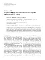
Upper arm
Spring
Damper
Tie rod
Lower arm
Tyre
Fig. 1.1. Rover 800 front suspension. (By courtesy of Rover Group.)
4
Introduction
[Ch. 1
frequencies are needed or the dynamic response required at frequencies well away
from a resonance, or a non-linear spring may be considered linear over a limited
range of extension, or certain elements and forces may be ignored completely if their
effect is likely to be small. Furthermore, the directions of motion of the mass elements
are usually restrained to those of immediate interest to the analyst.
Thus the model is usually a compromise between a simple representation which
is easy to analyse but may not be very accurate, and a complicated but more realistic
model which is difficult to analyse but gives more useful results. Consider for example,
the analysis of the vibration of the front wheel of a motor car. Fig. 1.1 shows a typical
suspension system. As the car travels over a rough road surface, the wheel moves up
and down, following the contours of the road. This movement is transmitted to the
upper and lower arms, which pivot about their inner mountings, causing the coil
Fig. 1.2(c). Motion in a vertical direction, roll, and pitch can be analysed.
Sec. 1.1]
Introduction
5
spring to compress and extend. The action of the spring isolates the body from the
movement of the wheel, with the shock absorber or damper absorbing vibration and
sudden shocks. The tie rod controls longitudinal movement of the suspension unit.
Fig. 1.2(a) is a very simple model of this same system, which considers translational
motion in a vertical direction only: this model is not going to give much useful
information, although it is easy to analyse. The more complicated model shown in
Fig. 1.2(b) is capable of producing some meaningful results at the cost of increased
labour in the analysis, but the analysis is still confined to motion in a vertical direction
only. A more refined model, shown in Fig. 1.2(c), shows the whole car considered,
translational and rotational motion of the car body being allowed.
If the modelling of the car body by a rigid mass is too crude to be acceptable, a
finite element analysis may prove useful. This technique would allow the body to be
represented by a number of mass elements.
The vibration of a machine tool such as a lathe can be analysed by modelling the
machine structure by the two degree of freedom system shown in Fig. 1.3. In the
simplest analysis the bed can be considered to be a rigid body with mass and inertia,
and the headstock and tailstock are each modelled by lumped masses. The bed is
supported by springs at each end as shown. Such a model would be useful for
determining the lowest or fundamental natural frequency of vibration. A refinement
to this model, which may be essential in some designs of machine where the bed
cannot be considered rigid, is to consider the bed to be a flexible beam with lumped
masses attached as before.
Fig. 1.3. Machinetool vibration analysis model.
6
Introduction
[Ch. 1
Fig. 1.4. Radio telescope vibration analysis model.
To analyse the torsional vibration of a radio telescope when in the vertical position
a five degree of freedom model, as shown in Fig. 1.4, can be used. The mass and
inertia of the various components may usually be estimated fairly accurately, but the
calculation of the stiffness parameters at the design stage may be difficult; fortunately
the natural frequencies are proportional to the square root of the stiffness. If the
structure, or a similar one, is already built, the stiffness parameters can be measured.
A further simplification of the model would be to put the turret inertia equal to zero,
so that a three degree of freedom model is obtained. Such a model would be easy to
analyse and would predict the lowest natural frequency of torsional vibration with
fair accuracy, providing the correct inertia and stiffness parameters were used. It
could not be used for predicting any other modes of vibration because of the coarseness
of the model. However, in many structures only the lowest natural frequency is
required, since if the structure can survive the amplitudes and stresses at this frequency
it will be able to survive other natural frequencies too.
None of these models include the effect of damping in the structure. Damping in
most structures is very low so that the difference between the undamped and the
damped natural frequencies is negligible. It is usually only necessary to include the
effects of damping in the. model if the response to a specific excitation is sought,
particularly at frequencies in the region of a resonance.
A block diagram model is usually used in the analysis of control systems. For
example, a system used for controlling the rotation and position of a turntable about