Photovoltaic systems and the national electric code
Bạn đang xem bản rút gọn của tài liệu. Xem và tải ngay bản đầy đủ của tài liệu tại đây (2.83 MB, 218 trang )
Photovoltaic Systems and the
National Electric Code
Used throughout the United States and many other countries, the
National Electric Code (NEC) is the world’s most detailed set of
electrical codes pertaining to photovoltaic (PV) systems.
Photovoltaic Systems and the National Electric Code presents a
straightforward explanation of the NEC in everyday language. The new
book is based on the 2017 NEC, which will be used widely until 2023,
with most of the interpretations and material staying true long after.
This book interprets the distinct differences between previous versions
of the NEC and the 2017 NEC and clarifies how these Code changes
relate specifically to photovoltaic installations.
Written by two of the leading authorities and educators in the field,
this book will be a vital resource for solar professionals, as well as
anyone preparing for a solar certification exam.
Bill Brooks is Principal Engineer at Brooks Engineering, Vacaville,
USA.
Sean White is a Solar PV professor, trainer and contractor in the USA.
Photovoltaic Systems and
the National Electric Code
Bill Brooks and Sean White
First published 2018
by Routledge
2 Park Square, Milton Park, Abingdon, Oxon OX14 4RN
and by Routledge
711 Third Avenue, New York, NY 10017
Routledge is an imprint of the Taylor & Francis Group, an informa business
© 2018 Bill Brooks and Sean White
The right of Bill Brooks and Sean White to be identified as
authors of this work has been asserted by them in accordance
with sections 77 and 78 of the Copyright, Designs and Patents
Act 1988.
All rights reserved. No part of this book may be reprinted
or reproduced or utilised in any form or by any electronic,
mechanical, or other means, now known or hereafter
invented, including photocopying and recording, or in any
information storage or retrieval system, without permission in
writing from the publishers.
Trademark notice: Product or corporate names may be
trademarks or registered trademarks, and are used only for
identification and explanation without intent to infringe.
British Library Cataloguing-in-Publication Data
A catalogue record for this book is available from the British Library
Library of Congress Cataloging-in-Publication Data
A catalog record for this book has been requested
ISBN: 978-1-138-08752-1 (hbk)
ISBN: 978-1-138-08753-8 (pbk)
ISBN: 978-1-315-11030-1 (ebk)
Typeset in Sabon
by Apex CoVantage, LLC
Contents
List of figures
List of tables
vii
ix
Introduction
1
1 Article 690 photovoltaic (PV) systems
4
2 Article 690 photovoltaic systems part II
circuit requirements
26
3 Section 690.12 rapid shutdown
58
4 Article 690 part III disconnecting means
74
5 Article 690 part IV wiring methods
88
6 Article 690 part V grounding and bonding
103
7 Article 690 part VI to the end of 690
123
8 Article 691 large-scale photovoltaic (PV) electric
power production facility
130
9 Article 705 interconnected electric power
production sources
138
10 Storage articles
168
vi
Contents
11 Chapters 1–4, Chapter 9 tables and Informative
Annex C
177
12 PV wire sizing examples
189
Index
199
Figures
0.1
1.1
1.2
1.3
1.4
1.5
1.6
1.7
1.8
2.1
2.2
2.3
2.4
2.5
2.6
3.1
3.2
3.3
3.4
3.5
3.6
4.1
4.2
1895 Niagara Falls power plant
1984 NEC (a much smaller Code book)
2014 NEC Figure 690.1(a) PV power source
2017 NEC PV Figure 690.1(a) PV power source
Interactive system [2017 NEC Fig 690.1(b)]
Ac module system [2017 NEC Fig 690.1(b)]
Dc coupled multimode system [2017 NEC Fig 690.1(b)]
Ac coupled multimode system [2017 NEC Fig 690.1(b)]
Stand-alone system [2017 NEC Fig 690.1(b)]
IV curve with different currents plotted showing
maximum circuit current, which is used for sizing
wires, above and beyond short circuit current
Partial datasheet from outback stand-alone inverter
Module interconnect for multiple parallel-connected
module circuits
Two PV source circuits backfeeding a short on
another PV source circuit
Fuses listed for PV
Dangerous dc arc-fault (do not try this at home)
AP system 4 module inverter
Rapid shutdown initiation switch
NEC Figure 690.56(C)(1)(a) reduced array shock
hazard sign
NEC Figure 690.56(C)(1)(b) conductors leaving
array level rapid shutdown sign
Buildings with more than one rapid shutdown type
example
Rapid shutdown sign
PV system disconnect sign
Finger safe fuse holder
2
5
8
9
10
10
11
13
14
37
39
47
53
53
57
63
66
68
69
71
72
76
84
viii
Figures
6.1
Fuse grounded PV array with one functional grounded
conductor
6.2 Bipolar PV array
6.3 Non-isolated inverter showing ground fault pathway
6.4 2017 NEC ungrounded PV array AKA transformerisolated inverter
6.5 Solidly grounded PV array
9.1 Feeder image showing where different parts of the
Code apply to different parts of the feeder
9.2 705.12(B)(2)(1)(a) sufficient feeder ampacity
9.3 705.12(B)(2)(1)(b) Overcurrent device protecting
feeder
9.4 Solar tap rules
9.5 25-foot tap rule
9.6 100% rule
9.7 705.12(B)(2)(3)(b) 120% rule
9.8 120% rule with multiple solar breakers acceptable
9.9 705.12(B)(2)(3)(c) sum rule
9.10 705.12(B)(2)(3)(d) center fed 120% rule
9.11 705.12(B)(3) marking label indicating multiple sources
9.12 Breakers over 1000V prices
12.1 Nicola Tesla demonstrates how to truly understand
3-phase in 1899
105
107
108
110
111
146
147
149
150
152
153
153
155
155
156
157
159
196
Tables
2.1
5.1
5.2
6.1
NEC Table 690.7(a) voltage correction factors for
crystalline and multicrystalline silicon modules
Table 690.1(A) correction factors (ambient temperature
correction factors for temperatures over 30°C)
Table 690.31(E) minimum PV wire strands for
moving arrays
NEC Table 250.122 EGC based on OCPD
30
91
96
116
Introduction
Photovoltaic is on the cover
of the 2017 NEC!
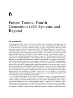
Photovoltaic (PV) is growing fast, and the PV material in the National
Electric Code (NEC) is changing faster than anything the NEC has
seen since the days of Thomas Edison and Nikola Tesla hashing it
out over dc vs. ac. It appeared that Tesla was right when 2-phase ac
power1 was installed at Niagara Falls and that ac was the way of the
future, but the future is always unpredictable and with PV, dc is making a comeback.
This book is designed to relay to the layperson working in the PV
industry the NEC PV-related material and changes as simply as possible, but not simpler. We hope that professional engineers (PEs) and
sunburnt solar installers alike will comprehend this easy writing style
and be entertained just enough to not be bored learning about a Code
that has been known to work better than melatonin on a redeye flight.
Since this book is about PV, rather than starting at the beginning
of the NEC, we will start with the most relevant article of the NEC,
which is Article 690 Photovoltaic (PV) Systems; we will then cover the
new Article 691 Large-Scale Photovoltaic (PV) Electric Power Production Facility which modifies Article 690 for large PV systems and then
dive into the interconnections of Article 705 Interconnected Electric
Power Production Sources where we understand how PV and other
power sources can connect to and feed other power sources, such
as the utility grid. The next articles we will cover are the articles on
energy storage, which are the old Article 480 Storage Batteries and the
new and more relevant in 2017 Article 706 Energy Storage Systems.
While we are on the subject of energy storage, we will cover the new
Article 710 Stand-Alone Systems (which was formerly 690.10) and
this will lead us to another new and renewable themed Article 712
Dc Microgrids. We will then go back to the beginning of the NEC
and look at Chapters 1 through 4 of the NEC, which apply to all wiring systems, including PV. We will see that, in covering the new and
2
Introduction
renewable PV centric articles, we already covered the more important
parts of Chapters 1 through 4 used for PV systems and all electric
installations, such as Article 250 Grounding and Bonding and Article
310 for wire sizing. There will be many times, when we are covering
material in Article 690, that we will go back and forth to other articles,
since this is the way to properly use the NEC.
The NEC is updated every three years with a new Code cycle.
This edition of Photovoltaic Systems and the National Electric Code
reflects the 2017 NEC and will discuss earlier versions of the NEC.
When the 2020 NEC comes out, this material will not be obsolete; in
fact more than half the PV in the United States is installed in places
that adopt the NEC three years after a Code is released. For instance,
the state with half of the solar in the US is California, and in California, the 2017 NEC is adopted in 2020 and used until the 2020 NEC
is adopted in 2023. It is also interesting to note that the proposals for
changes to the NEC are crafted three years earlier, so the material in
the 2017 NEC was proposed in 2014 and will be used on a regular
basis by inspectors until nine years later. Since the equipment changes
Figure 0.1 1895 Niagara Falls power plant
Courtesy Wikimedia
/>Westinghouse_Generators_at_Niagara_Falls.jpg
Introduction
3
so fast in the PV industry, the Code writers intentionally leave parts of
the Code open-ended to make way for new inventions that you may
come up with, which will save lives and may make you rich.
The 2017 NEC proposals for Article 690 and for other solar-relevant parts of the Code were first proposed at meetings at NREL in
Colorado in 2014 and put on a Word document by Bill Brooks. This
Word document grew, and the proposals were refined with a lot of
input. These future Codes were later proposed to the top dogs at the
National Fire Protection Association by Ward Bower (inventor of the
grid-tied inverter) and Bill Brooks of NEC Code Making Panel 4 in
Hilton Head, North Carolina.
Now is the time to take out your 2017 NEC and follow along to
understand PV and the NEC.
Note
1 The first power plant at Niagara Falls had two phases that were 90 degrees
out of phase with each other (weird). Now we use three phases that are
120 degrees out of phase with each other. This is interesting!
1
Article 690 photovoltaic (PV)
systems
Article 690 first came out in a little book known as the 1984 NEC and
has been updated and mostly lengthened ever since.
In comparing the original 1984 version of Article 690 to today’s
NEC, there are many similarities yet also quite a few differences. Time
to dig in!
Let us first list what we are dealing with in Article 690 before we
dig deep. This will give us perspective and familiarize us with how to
look things up quickly.
The NEC is also known as NFPA 70 and is divided into Chapters,
then Articles, then Parts and Sections.
For example, rapid shutdown requirements are found in:
NEC Chapter 6 Special Equipment
Article 690 Solar Photovoltaic (PV) Systems
Part II Circuit Requirements
Section 690.12 Rapid Shutdown of PV Systems on Buildings
Here is what we find in Article 690:
Article 690 solar photovoltaic (PV) systems
Part I general (part)
690.1 Scope [Section 690.1]
690.2 Definitions [There are more NEC definitions in Article 100,
such as the definitions for PV, ac and dc.]
690.4 General Requirements [They could not come up with a better title for this category.]
690.6 Alternating Current (ac) Modules
Article 690 photovoltaic (PV) systems
5
Figure 1.1 1984 NEC (a much smaller Code book)
Photo by Sean White
Part II circuit requirements
690.7 Maximum Voltage
690.8 Circuit Sizing and Current
690.9 Overcurrent Protection [Article 240 is also Overcurrent
Protection.]
690.10 Stand Alone Systems [This has been moved to Article 710
in the 2017 NEC.]
6 Article 690 photovoltaic (PV) systems
690.11 Arc-Fault Circuit Protection (Direct Current)
690.12 Rapid Shutdown of PV Systems on Buildings [Big changes]
Part III disconnecting means
690.13 Photovoltaic System Disconnecting Means
690.15 Disconnection of PV Equipment
Part IV wiring methods
690.31 Methods Permitted
690.32 Component Interconnections
690.33 Connectors
690.34 Access to Boxes
Part V grounding and bonding [Article 250 is also
grounding and bonding.]
690.41 System Grounding [Big changes in the 2017 NEC]
690.42 Point of System Grounding Connections
690.43 Equipment Grounding and Bonding
690.45 Size of Equipment Grounding Conductors
690.46 Array Equipment Grounding Conductors
690.47 Grounding Electrode System [Experts argue over a lot of
this article, which is interesting to observe.]
690.50 Equipment Bonding Jumpers
Part VI marking
690.51 Modules
690.52 Alternating Current Photovoltaic Modules
690.53 Direct Current Photovoltaic Power Source
690.54 Interactive System Point of Interconnection
690.55 Photovoltaic Systems Connected to Energy Storage Systems
690.56 Identification of Power Sources [This includes new Rapid
Shutdown signs.]
Part VII connection to other sources
690.59 Connection to Other Sources [Directs us to Article 705]
Part VIII energy storage systems
690.71 General [Directs us to Article 706]
690.72 Self- Regulated PV Charge Control
Article 690 photovoltaic (PV) systems
7
Now it is time to dive into the detail of Article 690.
Article 690 solar photovoltaic (PV) systems
Part I general (part)
690.1 scope (section 690.1)
Word-for-word NEC:
“690.1 Scope. This article applies to solar PV systems, other
than those covered by Article 691, including the array circuit(s),
inverter(s), and controller(s) for such systems. [See Figure 690.1(a)
and Figure 690.1(b).] The systems covered by this article may
be interactive with other electrical power production sources or
stand-alone or both, and may or may not be connected to energy
storage systems such as batteries. These PV systems may have ac
or dc output for utilization.
Informational Note: Article 691 covers the installation of
large-scale PV electric supply stations.”
Discussion: For the most part 690.1 is self-explanatory, however,
if we read the 2014 and the 2017 NEC carefully, we will notice that
energy storage systems (batteries) are no longer part of the PV system.
2017 NEC language:
“may or may not be connected to energy storage systems.”
2014 NEC language:
“may be interactive with other electrical power production sources
or stand-alone, with or without electrical energy storage such as
batteries.”
It takes some careful analysis of the language, but we see that being
connected to batteries in the 2017 NEC is different than with batteries
in the 2014 NEC.
So what does this mean for us? Batteries are no longer part of the
PV system as of the 2017 NEC and are part of a separate energy storage system that is covered in the new Article 706. Consequently, rapid
shutdown and other requirements that are specific to PV systems no
longer apply to the batteries.
8 Article 690 photovoltaic (PV) systems
Figure 1.2 2014 NEC Figure 690.1(a) PV power source
Courtesy NFPA
Next, we see diagrams that will show us the dividing line between
the PV system and not the PV system.
Section 690.1 also has some figures that we can look at in order to
get a picture of what we are talking about.
Figure 1.2 is an image from the 2014 NEC.
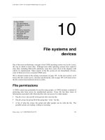
Figure 1.3 is an image from the 2017 NEC.
Figure 1.3 is from the 2017 NEC with the added dc-to-dc converter.
From comparing these images, the main difference here is the insertion of the dc-to-dc converters. The writers of the NEC left the dc-todc converter definition open-ended for your billion-dollar invention.
2017 dc-to-dc converters are usually one per module, rather than three
modules per converter in this image. Take note that, as we will learn
coming up in Section 690.12 Rapid Shutdown, in 2019 the 2017 NEC
will increase requirements for rapid shutdown on buildings and module level shutdown may be one of the only methods to comply. However, new inventions in the meantime could introduce other methods
not currently foreseen.
Article 690 photovoltaic (PV) systems
Figure 1.3 2017 NEC PV Figure 690.1(a) PV power source
Courtesy NFPA
It is interesting to note that the solar cells in the diagram have
gone from round in the 2014 NEC (really old style) to square in
the 2017 NEC (polycrystalline). For someone first learning about
solar, it could be confusing to see a solar module with 12 cells and
then to see panels made of three modules. It would be even more
confusing to have one dc-to-dc converter per three modules that
is being connected with fuses to a dc-to-dc converter combining
busbar and then off to a dc-to-dc converter output circuit. Dc-to-dc
converters being installed in 2017 have a single PV module with
a dc-to-dc converter under the module and then a number of
dc-to-dc converters connected in series, and then the dc-to-dc
converter source circuit is connected directly to the inverter.
9
10 Article 690 photovoltaic (PV) systems
Figure 1.4 Interactive system [2017 NEC Fig 690.1(b)]
Courtesy NFPA
Figure 1.5 Ac module system [2017 NEC Fig 690.1(b)]
Courtesy NFPA
Images are good to learn from. Next, we will go over the different
images in Figures 690.1(B), paying close attention to the various PV
system disconnecting means, which separate the PV system covered
here in Article 690 from systems covered in other areas of the 2017
Code. Remember, much of this has changed in the 2017 NEC.
Interactive (grid-tied) inverter circuits are very simple. The inverter
is used only for PV power; it has no other purpose and therefore is
part of the PV system.
A big question installers have is: “What is the difference between an
ac module and a microinverter bolted to a PV module?” The answer
is that if the PV module was listed to UL1703 while the inverter was
bolted to it and the inverter was tested and listed to UL 1741 while bolted
to the PV module, then it is an ac module and we do not consider dc
part of the product when installing this module.
Article 690 photovoltaic (PV) systems
11
If the module and microinverter were not listed together, then we
are responsible for applying the NEC to the dc circuit going from
the module to the inverter. It is also interesting to note that the
word microinverter does not appear in the NEC. The NEC looks
at a microinverter as nothing more than a small (micro) inverter.
There is a lot of information in Figure 1.6. First of all, dc coupled
and multimode are different things, which can go together. A dc coupled system is a PV system that is typically charging batteries with a
charge controller connected to a PV array. The inverter in a dc coupled system will be coupled with the inverter and the charge controller
working with dc voltage. In fact, it is possible to have a dc coupled
system that does not have an inverter, but most people would like to
utilize ac electricity with their dc coupled systems.
As we can see in the 690.2 Definitions that we are about to dive into, a
multimode inverter is an inverter that can work in different modes, such
as stand-alone (off-grid) and interactive (grid-tied). This type of inverter
was also known as a bimodal inverter for a time and will have different
outputs. One output will go to the stand-alone (backed up) loads and
the other output will go to the loads that are not backed up and to the
grid. When the power goes down, the interactive output of the inverter
Figure 1.6 Dc coupled multimode system [2017 NEC Fig 690.1(b)]
Courtesy NFPA
12 Article 690 photovoltaic (PV) systems
will act exactly as an interactive inverter and anti-island (stop sending
voltage or current to the grid). No interactive inverter circuit is allowed
to be an “island of power” and must disconnect from the grid.
Multimodal vs. hybrid
There is often confusion about multimodal inverters and hybrid
PV systems.
A hybrid system is defined in Article 100 Definitions as, “A system comprised of different power sources. These power sources
could include photovoltaic, wind, micro-hydro generators, enginedriven generators, and others, but do not include electric power
production and distribution network systems. Energy storage systems such as batteries, flywheels, or superconducting magnetic storage equipment do not constitute a power source for the purpose of
this definition.” What we are saying here is that being connected
to the grid has nothing to do with being hybrid. Hybrid has to do
with having multiple sources of power, not including energy storage or the grid. A multimodal system is, as we have mentioned, one
that can work in grid (interactive) or off-grid (stand-alone) mode.
Ac coupled systems are becoming more popular. There are arguments on each side, whether it is best to add energy storage to PV
systems via ac coupled and dc coupled systems (or both). Ac coupled
systems have the benefit of being able to use regular grid-tied inverters
in the system and the drawback of having two kinds of inverters.
In Figure 1.7, starting at the upper left, we have a PV array and an
interactive inverter, which is the PV system according to the 2017 NEC.
On the other hand, according to the 2014 NEC, almost everything in
the image is the PV system. We can see that the border that separates
the PV system from the rest of the ac coupled multimode system is the
PV system disconnect. It is surprising to many that the multimode
inverter has no place to connect PV to it. This inverter is connected
to an energy storage system (usually batteries) on the dc side and to
the grid (electrical production and distribution network) on one ac
output and to what I like to call the “ac microgrid” on the other ac
circuit, where backed up loads can usually operate. It is also interesting
that some manufacturers can make ac coupled systems that will not
operate at all when the grid is down. This can be for what is often
called “self-consumption” in the industry. These systems will be able
to send electricity from the batteries to the loads or the grid when it is
Article 690 photovoltaic (PV) systems
13
Figure 1.7 Ac coupled multimode system [2017 NEC Fig 690.1(b)]
Courtesy NFPA
beneficial to do so because of utility demand charges, time-of-use rate
schedules or because in some places, utility customers are not allowed
to export energy.
The stand-alone system in the image above has a few differences
with the average stand-alone system we see in the field. First of all,
there is usually a charge controller that is connected to three different
things. First is the PV array, second is the energy storage system and
third is the inverter. These days, it is unusual to have dc loads as shown
in Figure 1.8.
Figure 1.8 could also be considered a dc coupled system without a
multimode inverter.
690.2 definitions
Because this book is meant to be read with an actual NEC book handy
or to be read by someone already familiar with the NEC, we will not
repeat every easy to understand definition in Article 690. We will
repeat the language of some of the newer and more difficult to understand definitions that a solar professional will have a tendency to use
in their career. We will also add discussion to some definitions.
Alternating current (ac) module
Discussion: The question that many solar professionals have is: “What
is the difference between an ac module and a microinverter attached
14 Article 690 photovoltaic (PV) systems
Figure 1.8 Stand-alone system [2017 NEC Fig 690.1(b)]
Courtesy NFPA
to a module?” The answer is that the ac module has the microinverter
attached to it before it goes through the UL 1703 PV testing and the
UL 1741 inverter testing (also see Figure 1.5, page 10 of this book).
Bipolar photovoltaic array
Discussion: A bipolar PV array is dc power analogy of 120/240Vac
power on a house in the US. In a bipolar system there is a positively
grounded array section and a negatively grounded array section on
the same inverter. This means that we can have voltage to ground that
is half of the total voltage that the inverter is getting the benefit of
processing. The interesting thing about this, in the 2017 NEC, is that
with the 1500Vdc to ground equipment, we can have an inverter with
a 3000Vdc input in a ground mount PV system!
This is not something anyone is likely to see in his or her backyard,
but according to the 2017 Code, it is a possibility.
At NREL in 2014, Sean and Bill made a proposal to require lithium
batteries for bipolar arrays for the 2017 NEC, but everyone just
laughed at them.