SCE GET OM 2012 03 v1
Bạn đang xem bản rút gọn của tài liệu. Xem và tải ngay bản đầy đủ của tài liệu tại đây (792.36 KB, 8 trang )
Steam Cabinet Operator’s Manual
www.profitind.com
Steam Cabinet
Operator’s Manual
SCE-1-N2-GET
Single door steam cabinet
SCE-3-N2-GET
Three door steam cabinet
This manual must be retained for future reference
FOR YOUR SAFETY
Do not store or use gasoline or other flammable
vapors or liquids in the vicinity of this or any other
appliance.
CAUTIONS
• Improper
•
All rights reserved. All trademarks are the property of their respective owners.
Reproduction in whole or in part without written permission is prohibited.
SCE-GET-OM-2012-03-V1
installation, adjustment, alteration,
service or maintenance can cause property damage,
injury or death. Read the installation and operator’s
instructions thoroughly before installing or servicing
this equipment.
All installations must conform with local codes, or in
the absence of local codes, with the National Fuel Gas
Code, ANSI Z233.1 / NFPA 54 or Natural Gas and
Propane Installation Code, CSA B149.1
NOTE: To keep this appliance area free and clear from combustibles.
Steam Cabinet Operator’s Manual
Steam Cabinet Operator’s Manual
Technical service contacts
HONG KONG
Pro-Fit Industrial Co. Ltd.
Flat A, 8/F., Chung Shun Knitting Centre,
1-3 Wing Yip Street, Kwai Chung, N.T., Hong Kong.
Phone : (852) 2371-2862
Fax :
(852) 2371-2867
E-mail :
Website : www.profitind.com
CHINA
Guangdong
Foshan Fordex Kitchen Utensils Co. Ltd.
Phone : (86) 0757-86417222
Fax :
(86) 0757-86417233
E-mail:
BEIJING
Fortune-Cater Equipment Co., Ltd.
Phone : (86) 010-67676228
Fax :
(86) 010-67620538
E-mail:
SINGAPORE & MALAYSIA
Phone : (60) 17-2255446
Fax :
(603) 91714788
E-mail:
SCE-GET-OM-2012-03-V1
P. 12
Contents
Specifications
2-4
Structure of the steam cabinet
5-7
Structure of the combustion system
Operation
8
9-10
General information and maintenance
11
Technical service contacts
12
Steam Cabinet Operator’s Manual
Steam Cabinet Operator’s Manual
Operation
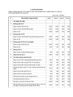
Specifications
SCE-1-N2-GET
WHAT TO DO IF YOU SMELL GAS:
•
•
•
•
•
•
•
Do not light any appliance
Do not touch any electric switch
Do not use any phone in your building
Immediately call your gas supplier from a phone outside the building
Follow your gas supplier’s instructions
If your gas supplier cannot be reached, call the fire department
Installation and service must be performed by a qualified installer, service agent or the gas
supplier
General information and maintenance
1.
2.
3.
4.
5.
Manufacturer
PRO-FIT - Brand : Power Flame
Model no.
SCE-1-N2-GET
Product Description
Environmental type single door steam cabinet, gas heated
Origin
Hong Kong, PRC
Function
Steaming (batch steaming of fish, rice, dim-sum, rice cake & braising soup)
700 x 910 x 1800mmH (27.6” x 35.8” x 70.9”H)
- One large half door can fit in 7 tiers of bar type stainless steel shelf
- With 4 nos. of 2.28” dia. full height stainless steel adjustable feet
Construction
Engineering/
MEP ratings
- With side swing door and one heavy duty & heat resistant latch
- Lower part burner housing is constructed of 0.08” (2.0mm) thick 304, with no. 4 finishing stainless
steel sheet heat exchange type steam generator heated from 4 nos. of less heat-input high speed turbo
jet burners; steam will be discharged from the discharge cap located on top of the generator
- Electronic ignition
- Electrical requirement for solenoid 0.0154 kW (110-120V/1ph/50~60Hz) or
(220-240V/1ph/50~60Hz)
- Heat input :
Propane Gas : 45kW (153 546 BTU / hr )
Natural Gas : 45kW (153 546 BTU / hr )
Town Gas : 45kW (153 546 BTU / hr )
Sanitation
All stainless steel construction for easy cleaning
Accessories
- With seven stainless steel slatted bar type shelves equally distributed in seven intervals inside the
cabinet with shelf supporting angles located equally on both sides of the cabinet
Safety
- With safety valve – flame failure device
- Over heat protection for heat exchange chamber
- Excess steam release valve
Particulars
- Able to generate steam at 100oC within 8 minutes
- Noise level is less than 70dB
- Flue temperature at exhaust chamber is less than 200oC
SCE-GET-OM-2012-03-V1
P. 2
6.
7.
8.
9.
If the pilot flame does not light up, do not turn on the Main Gas Cock handle.
If the pilot flame does not light up, try to press the Electronic Ignition Button again. If it still fails,
inform the qualified service agent to take appropriate action on maintenance and replacement.
Remember to turn off the Pilot Light Valve while not in cooking for an extended period of
time.
The kitchen exhaust system must be turned on whenever the appliance is in operation.
Always pay attention to any gas leakage from the Main Gas Cock Valve andconnection joints of
the gas pipes. If there is leakage problem, shut off the main gas supply valve, open the windows
and inform the qualified service agent for maintenance.
Clean and drain the water tank daily.
When the appliance is idle, clean it up and always keep it tidy.
To avoid damages on the cabinet body, do not strike bulky and heavy objects onto the cabinet.
Important Notes:
Operator MUST drain away water completely inside heat exchange chamber everyday after
use and MUST turn off the drainage valve after each drainage to avoid damage to the chamber.
If countries have hard water system, water softener for water supply to the chamber must be
added.
Descriptions
Body and water tunnel
Flue
Main gas valve
Pilot light valve
Flame failure device (safety valve)
Electronic ignition
Burners
Automatic pilot sensor
Heat exchange chamber
Water float ball device
Water tank
Steam compartments
Water valve
●
○
Maintenance and Time Intervals
Daily
Weekly
Necessary works
General cleaning
○
Leakage check
Leakage check
Leakage check
Performance check
Performance check
General cleaning
○
Performance check
Performance check and
replacement (if needed)
Drainage check
○
Performance check
General cleaning
○
General cleaning
○
Leakage check
Every 3 months
Half-yearly
●
●
●
●
●
●
●
○
○
Repair and maintenance must be done by qualified person.
General maintenance can be carried out by end-users.
Note: Disconnect the power supply to the appliance before cleaning or servicing, if applicable.
For technical support, please refer to the page of Technical Service Contacts.
P. 11
SCE-GET-OM-2012-03-V1
Steam Cabinet Operator’s Manual
Steam Cabinet Operator’s Manual
Operation
Specification
Three Door Steam Cabinet (SCE-3-N2-GET)
SCE-3-N2-GET
5
1.
2.
3.
4.
5.
6.
7.
8.
9.
10.
11.
12.
13.
1
Exhaust tunnel
Steam compartments with release device
Steam vent duct
Drainage channel
Hinged door with latch
Steam control handle
Flame failure device (safety valve)
Pilot light
Electronic ignition
Inspection hole
Main gas cock handle
Adjustable bullet feet
Heat exchange chamber-Water drainage valve
6
2
3
4
9
7
8
11
10
12
13
* This appliance is only for professional use and that it should be used by qualified people.
TURN ON
a.
b.
c.
d.
e.
Turn on the exhaust fan to keep the kitchen in good ventilation. Make sure water in the water tank is
up to the standard level.
Before lighting the appliance, ensure all gas valves are in closed position.
Turn on the Pilot Light (8). Press the Ignition Button (9) and Flame failure device (safety valve) (7)
simultaneously to light the pilot. Once pilot flame is established, hold the buttons for 30 seconds.
If the pilot flame is not lit, wait for 5 minutes before attempting step (c).
Turn on the the Main Gas Cock (11) until a desirable flame is obtained. Steam will be produced
shortly (normally in 8 minutes).
Step 1
Step 2
Turn on the
pilot light
Press the safety
valve and
ignition button
simultaneously &
hold for 30 sec.
Manufacturer
PRO-FIT - Brand : Power Flame
Model no.
SCE-3-N2-GET
Product Description
Environmental type three door steam cabinet, gas heated
Origin
Hong Kong, PRC
Function
Steaming (steam fish, rice, dim-sum, rice cake & braising soup)
Dimensions
850 x 910 x 1900mmH (33.5” x 35.8” x 74.8” H)
- Two upper decks height of 24.6” x 24.6” x 7.88” each and one lower deck of 24.6” x 24.6” x 14.0”
- With 4 nos. of 2.28” dia. full height stainless steel adjustable legs
Construction
- With pull down spring assisted door with cam lock & heat resistant handle for each deck
- Lower part burner housing is constructed of 0.08” (2.0mm) thick 304, with no. 4 finishing stainless
steel sheet heat exchange type steam generator heated from 4 nos. of less heat-input high speed turbo
jet burners; steam will be discharged from the discharge cap located on top of the generator
- Electronic ignition
Engineering/
MEP ratings
- Electrical requirement for solenoid 0.0154 kW (110-120V/1ph/50~60Hz) or
(220-240V/1ph/50~60Hz)
- Heat input :
Propane Gas : 45kW (153 546 BTU / hr )
Natural Gas : 45kW (153 546 BTU / hr )
Town Gas : 45kW (153 546 BTU / hr )
Sanitation
All stainless steel construction for easy cleaning
Accessories
- With one stainless steel slatted bar type shelf per deck and one extra shelf of same kind with shelf
supporting angle located at mid-level of the lower deck
Safety
- With safety valve – flame failure device
- Over heat protection for heat exchange chamber
- Excess steam release valve
Particulars
- Each compartment is furnished with individual pulling type steam volume control puller & accessible
water tank with floating valve
- Able to generate steam at 100oC within 8 minutes
- Noise level less than 70dB
- Flue temperature at exhaust chamber less than 200oC
Step 3
Turn on the
main cock
SHUT OFF
a.
b.
For temporary shut off, just turn off the Main Gas Cock (11). Leave the Pilot Light (8) on.
If the appliance is not in use, turn off all the gas valves. Also shut off Drainage Gate Valve (13) after
draining water off from the chamber.
Temporary shut off
Not in use
Leave the
pilot light on
Turn off the
pilot light
. Turn off the
main cock
. Turn off the
main cock
Important Notes SCE-GET-OM-2012-03-V1
Make sure water is removed from the heat exchange chamber at least once a day and turn off the
drainage valve after each drainage to avoid damage to the chamber
If countries have hard water problem, water softener must be added to supply soft water to the
chamber
Wear thermal gloves during hot dish move-in/out of steam compartment
P. 10
P. 3
SCE-GET-OM-2012-03-V1
Steam Cabinet Operator’s Manual
Steam Cabinet Operator’s Manual
Specifications
Operation
Single Door Steam Cabinet (SCE-1-N2-GET)
9
SCE-1-N2-GET
Single Door Steam Cabinet
1
SCE-3-N2-GET
Three Door Steam Cabinet
10
2
3
4
5
6
7
8
*
11
12
13
14
1.
2.
3.
4.
5.
6.
7.
8.
9.
10.
11.
12.
13.
14.
Exhaust tunnel
Steam compartments with release device
Steam vent duct
Pilot light
Flame failure device (safety valve)
Water tank cover
Drainage channel
Adjustable bullet feet
Hinged door with latch
Stainless steel shelf
Main gas cock handle
Electronic ignition
Inspection hole
Heat exchange chamber - Water drainage valve
This appliance is only for professional use and that it should be used by qualified people.
TURN ON
a.
b.
c.
d.
e.
Turn on the exhaust fan to keep the kitchen in good ventilation. Make sure water in the water tank is up to the standard
level.
Before lighting the appliance, ensure all gas valves are in closed position.
Turn on the Pilot Light (4). Press the Ignition Button (12) and Flame failure device (safety valve) (5) simultaneously to
light the pilot. Once pilot flame is established, hold the buttons for 30 seconds.
If the pilot flame is not lit, wait for 5 minutes before attempting step (c).
Turn on the Main Gas Cock (11) until a desirable flame is obtained. Steam will be produced shortly (normally in 8
minutes).
Specifications of Steam Cabinet
Step 1
Single Door
SCE-1-N2-GET
Three Doors
SCE-3-N2-GET
Width x Depth x Height (inch)
27.6 x 35.8 x 70.9
33.5 x 35.8 x 74.8
Width x Depth x Height (mm)
700 x 910 x 1800
850 x 910 x 1900
Model ►
Step 2
Turn on the
pilot light
Press the safety
valve and
ignition button
simultaneously &
hold for 30 sec.
Dimensions
Solenoid
Loading (kW) Voltage (V/Ph/Hz)
Step 3
Turn on the
main cock
0.0154 (110~240/1/50~60)
Heat input kW (BTU / hr.)
Town Gas
45 (153546)
45 (153546)
SHUT OFF
Propane (L.P. Gas)
45 (153546)
45 (153546)
Natural Gas
45 (153546)
45 (153546)
a.
b.
Operating Pressure (inch in Water Column)
Town Gas
Propane (L.P. Gas)
Natural Gas
Fuel pipe connection (inch)
Town Gas
Propane (L.P. Gas)
Natural Gas
Water inlet / Drainage pipe (inch)
Water inlet / Drain
Net / Gross Wt. (kgs)
6
11
7
6
11
7
Ø1
Ø1
Ø1
Ø1
Ø1
Ø1
Ø0.5 / Ø1.5
Ø0.5 / Ø1.5
165 / 242
200 / 322
For temporary shut off, just turn off the Main Gas Cock (11). Leave the Pilot Light (4) on.
If the appliance is not in use, turn off all the gas valves. Also shut off Drainage Gate Valve (14) after draining water off
from the chamber.
Temporary shut off
Not in use
Leave the
pilot light on
Turn off the
pilot light
. Turn off the
main cock
. Turn off the
main cock
Important Notes -
SCE-GET-OM-2012-03-V1
P. 4
Make sure water is removed from the heat exchange chamber at least once a day and turn off the drainage valve after each
drainage to avoid damage to the chamber
If countries have hard water problem, water softener must be added to supply soft water to the chamber
Wear thermal gloves during hot dish move-in/out of steam compartment
P. 9
SCE-GET-OM-2012-03-V1
Steam Cabinet Operator’s Manual
Steam Cabinet Operator’s Manual
Structure of the Combustion System
Structure of the Steam Cabinet
Single Door Steam Cabinet
1. Single Door Steam Cabinet is constructed of high quality stainless steel
with three major portions: the stainless steel turbo jet burners, the upper
steam cabinet body and the stainless steel heat exchange chamber.
2. The upper steam cabinet body is constructed of stainless steel with slatted
bar type shelves, steam inlet and water drainage holes. The exterior body
is constructed of water drainage channel, stainless steel cover panels, door
with gasket to prevent leakage of steam and steam release device.
3. The heat exchange chamber is newly designed. It can produce a great
volume of powerful steam from the heat exchange chamber in a short
while. Steam is an extremely efficient heat transfer medium, it goes up
from cap opening and carries a great deal of heat energy which readily
transfers directly to the food and therefore more time and power can be
saved. The inbuilt water tank is equipped with automatic float ball device
to control water level and check cover. To ensure safety, the steamer is
equipped with overheat device and cut off to heat exchange chamber as
well as the flame failure device (safety valve) to ensure safety operation.
4. The gas burner system is equipped with specially designed stainless steel
turbo jet burners, the flue, the frame, the side and the front cover panels
and adjustable bullet feet. The front panel is equipped with main cock
handle, pilot light, flame failure device (safety valve), the inspection hole,
the electronic ignition, etc.
Three Door Steam Cabinet
No.
Parts Name
Recommended
Replacement parts list
Installed & adjusted by
Installer and / or service agent
1
Gas supply pipe
2
Main gas cock handle
9
3
Main gas valve
9
4
Pilot valve knob
9
5
Pilot valve
9
9
6
Flame failure device (safety valve)
9
9
7
Electronic ignition with battery box
9
9
8
Automatic pilot sensor
9
9
9
Pilot head
9
9
10
Pilot burner
9
9
11
Stainless steel turbo jet burner
9
9
12
Overheat sensor device with sensor tip
9
9
13
Pressure test point
9
9
14
Main gas-in jet
9
9
15
Pilot Jet
9
9
16
Solenoid
9
9
SCE-GET-OM-2012-03-V1
P. 8
9
1. The three door steam cabinet is constructed of high quality stainless steel
with three major portions: The stainless steel turbo jet burners, the upper
steam cabinet body and the stainless steel heat exchange chamber.
2. The upper steam cabinet body is consisted of three individual steaming
compartments equipped with slatted bar type shelves, steam inlets and
water drainage holes. The exterior body is equipped with water drainage
channels, cover panels, steam control devices and doors with gasket on
the door edge and special clam lock designed handle to prevent leakage
of steam.
3. The newly designed heat exchange chamber generates a great volume
of powerful steam in a short while. Powerful steam generated from that
steam boiler and goes into steaming compartments from individual steam
inlet tunnel for food steaming. Stainless steel built-in water tank equipped
with automatic float ball device to control water level. With over-steam
safety devices to secure a safety and easy operation.
4. The gas burner systems are equipped with four numbers of individual
specially designed stainless steel turbo jet burners and controlled by two
main gas cocks to allow better control of flame output. The front panels
are equipped with two main cock handles, pilot light, flame failure device
(safety valve), electronic ignition and inspection hole etc.
P. 5
SCE-GET-OM-2012-03-V1
Steam Cabinet Operator’s Manual
Steam Cabinet Operator’s Manual
Structure of Single Door Steam Cabinet
Structure of Three Door Steam Cabinet
SCE-1-N2-GET
No.
SCE-GET-OM-2012-03-V1
Name
SCE-3-N2-GET
Quantity
1
Door gasket
1
No.
2
Door hinge
2
1
3
Door latch
1
4
Water tank cover
5
Water tank with floating ball valve
6
Quantity
No.
Door gasket (upper doors)
2
10
Adjustable bullet feet
4
2
Steam inlet control knob
3
11
Stainless steel turbo jet burner
4
1
3
Door latch
3
12
Pilot burner
1
1
4
Door gasket (lower doors)
1
13
Exhaust channel (upper part)
1
Heat exchange chamber
1
5
Door spring
6
14
Exhaust channel (lower part)
1
7
Adjustable bullet feet
4
6
Door hinge
6
15L S/S Casing for door spring (Left)
3
8
Stainless steel turbo jet burner
4
7
Water tank cover
1
15R S/S Casing for door spring (Right)
3
9
Pilot burner
1
8
Water tank with floating ball valve
1
10
Abgaskanal
1
9
Heat exchange chamber
1
P. 6
Name
P. 7
Name
Quantity
SCE-GET-OM-2012-03-V1