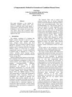
A PRACTICAL METHOD FOR DESIGN OF COASTAL STRUCTURES IN SHALLOW WATER
Bạn đang xem bản rút gọn của tài liệu. Xem và tải ngay bản đầy đủ của tài liệu tại đây (271.27 KB, 11 trang )
A PRACTICAL METHOD FOR DESIGN OF COASTAL STRUCTURES
IN SHALLOW WATER
Henk Jan Verhagen1, Gerbrant van Vledder1,2, Sepehr Eslami Arab1
Modern design formula for coastal structures (like rock stability formula and overtopping
formula use wave parameters (H2% and Tm-1,0) which are not readily available from
standard boundary condition wave data. For transforming values like Hs and Tp to the
parameters used in the new formulas, often-fixed conversion factors are used. However,
this may lead to significant errors. Therefore, it is better to calculate these new parameters
with an appropriate wave transformation model. The one-dimensional Graphical User
Interface for SWAN (SwanOne) is presented as a simple tool to perform the required
transformation.
INTRODUCTION
Recent research has shown that for wave structure interaction in case of
shallow water, the spectral period based on the first negative moment of the
energy spectrum(Tm-1.0) is a better descriptor than a mean period or the peak
period of the spectrum. On this basis in the Rock Manual [2007], several
equations for run-up, overtopping and structural stability are presented. Also in
the new EurOtop Overtopping Manual [2007], this parameter is used. The Rock
Manual also indicates that for structural stability the parameter H2% is a better
descriptor than the Hs or the Hm0. However, the determination of these
parameters is not yet standard procedure, and often conversion values are used
(e.g. H2%/Hm0 = 1.4 and Tm-1,0/Tp = 1.1; and therefore implicitly assuming a Rayleigh distribution and a Jonswap spectral shape with peak enhancement factor γ
=3.3 and an f-5 spectral tail).
However, by using these standard conversion factors the advantages of the
new approach completely disappear, because for non-standard coasts the conversion factors are different because the near shore spectral shape differs from
deep water. Exactly in those cases, the new approach is valuable.
NEW GUIDANCE
The Rock Manual
The Rock Manual [2007] gives two sets of equations for the determination
of the stability of rock armour. In the manual, the equations 5.136/137 are for
deep water and the equations 5.139/140 are for shallow water. The validity of
1
Delft University of Technology, Faculty of Civil Engineering and Geosciences, Section
Hydraulic Engineering, PO Box 5048, NL2600GA Delft, The Netherlands,
; ;
2
Alkyon, PO Box 248, NL8300AE Emmeloord, The Netherlands,
1
2
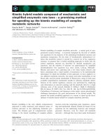
these formulas is in the manual indicated by means of a figure (Figure 1 in this
paper). Each set consists of an equation for plunging waves and an equation for
surging waves. In this paper only the plunging conditions will be discussed,
since for surging waves an identical elaboration can be followed.
The definition of “shallow” water is not very exact. An intermediate area exists
between the validity of the deep and shallow equations. Therefore it is handy to
come to one single formula valid for both deep and shallow water conditions.
Figure 1: Validity of the rock stability equations according to the Rock Manual [2007]
The formula for deep water presented in the Rock Manual is:
Hs
⎞
= c pl P 0.18 ⎛⎜ S
⎟
N
ΔDn 50
⎝
⎠
0.2
1
ξm
(5.136)
in which cpl =6.2 with a standard deviation of 0.4 (so for design one should
apply cpl = 5.5).
For shallow water conditions, the Rock Manual recommends:
0.2
Hs
⎞ ⎛ Hs ⎞ 1
= c pl P 0.18 ⎛⎜ S
⎟ ⎜
⎟
N ⎠ ⎝ H 2% ⎠
ξ m −1,0
ΔDn 50
⎝
(5.139)
In which cpl = 8.4 with a standard deviation of 0.7 (so for design apply cpl =
7.25).
In deep water, assuming a Rayleigh distribution there is a fixed relation
between:
Hs = 1.41 H2% and (assuming a Jonswap spectrum with γ =3.3)
Tm = 0.92 Tm-1,0
(Tp = 1.20 Tm and Tp = 1.1 Tm-1,0)
This means that both equations 5.136 and 5.139 can be written as:
3
H 2%
⎞
= c pl P 0.18 ⎛⎜ S
⎟
N⎠
ΔDn 50
⎝
0.2
1
ξ m −1,0, H
2%
(for details is referred to the Appendix).
Note that in the Iribarren number also the parameter H2% is used instead of Hs.
Of course, the coefficient cpl and csu are different for plunging and surging
waves:
• For shallow water cpl =8.4 and csu = 1.3 (direct from Rock Manual)
• For deep water
cpl =8.2 and csu = 1.5 (converted values)
This difference is small, but not negligible. The coefficients for equation 5.139
originate from Van Gent et.al [2003]. Because most of the tests in that paper are
for shallow water, the Rock Manual recommends using the Van Gent
coefficients for shallow water and the Van der Meer coefficients for deep water.
Some probable reason for the difference between the coefficients has been
discussed by Verhagen et al.[2006] as well as by Muttray and Reedijk [2008].
In conclusion one finds that for both deep and shallow water conditions
calculations best can be carried out using the H2% and the Tm-1,0.
The Overtopping Manual
For the calculation of run-up and overtopping all available and recommendable methods are presented in the EurOtop manual [2007]. Nearly all
equations in this manual use Tm-1,0 as a parameter for the wave period. For the
wave height, in general the Hm0 is used. However, the manual recommends,
“Although prediction methods in this manual are mainly based on the spectral
significant wave height, it might be useful in some cases to consider also other
definitions, like the 2%-wave height H2% or H1/10, the average of the highest
1/10-the of the waves.” Unfortunately, the manual does not recommend when to
do this. In conclusion one finds that also for the calculation of run-up and overtopping the parameters the H2% and the Tm-1,0 are important.
AVAILABLE TOOLS
It is essential to determine the H2% and the Tm-1,0 as correct as possible. The
use of “standard” conversion factors is not to be recommended, especially not in
shallow water. This may lead to rather significant errors, as will be
demonstrated in the example at the end of this paper.
Determination of H2%
For the determination of the H2% the Battjes-Groenendijk method [Battjes
and Groenendijk, 2000] can be applied. The method is quite straightforward,
because the required parameters are all given in the mentioned paper. The
method is based on data from a flume experiment with foreshore slopes of 1:20
to 1:250.
However, all these slopes are for continuous slopes, not a varying profile.
According to Battjes and Groenendijk, the effect of the bottom slope is of
4
secondary nature. In case of a varying bed slope, it is suggested to use the
average local bed slope, measured over a wavelength offshore of the point under
consideration.
Determination of Tm-1,0
In order to obtain a value for Tm-1,0, one needs the local shallow water wave
spectrum. Such a spectrum can be obtained by flume tests or by using a spectral
wave model, like SWAN. For daily engineering use, SWAN [Booij et.al, 1999] is
used with a Graphical User Interface (GUI). For SWAN, different organisations
have produced GUI’s which are commercially available. Most GUI’s require as
input a two dimensional depth matrix; but for many cases a one dimensional
computation is sufficient.
For simple calculations
SWAN, even running via a
user friendly GUI, is still
quite some work.
Therefore, an existing onedimensional GUI for SWAN
has been updated. This new
GUI, SwanOne, requires as
input only a simple (format
free) ASCII file with one
profile
(distances
and
depths), as well as the deepwater wave height, mean
wave period and direction.
Figure 2: Typical input screens of SwanOne
5
One may also enter the orientation of the profile, the direction of the waves, as
well as additional wind and/or currents. The output of SwanOne is at any selected point not only the spectrum, but also values of Tm-1,0, Hm0 and H2%.
The previous version of SwanOne was written in Visual Basic and had an
in-build version of SWAN. The disadvantage of this approach was that new
releases of SWAN could not be implemented in SwanOne in an easy way. The
new version of SwanOne is written as MatLab routines. It is available as a set of
routines as well as in the form of a compiled version, which can be used without
having a MatLab licence.
Although the package uses the one-dimensional option of SWAN, it is still
possible to calculate directional spectra. Since the one-dimensionality only comprises the spatial variation, the only limitation is in fact that the package
assumes parallel depth contour lines. For many engineering problems this is a
very acceptable limitation.
Operation of SwanOne
is very easy. An input-file
has to be made containing
the depth information. This
is a simple ASCII-file with
distance and depth (with
respect to Chart Datum). In
the menus, one can define
the orientation of the
coastline, the profile, the
wave direction. A wind
speed and wind direction can
be added, as well as a
waterlevel (difference with
Chart Datum). In addition,
optional current data can be
entered. Wave heights at the
seaward boundary are given
Figure 3: Sample output spectrum
as wave height (Hm0) and
wave period (Tp) and an
incident wave direction θ. The program then calculates the input spectrum
(assuming a Jonswap spectrum). Alternatively, one may also enter a file with an
arbitrary spectrum.
Two types of output are possible, a graph of key parameters as a function
of the distance, and spectra on pre-selected locations.
6
CALCULATIONS PERFORMED
In order to investigate if such a simplified one-dimensional approach is
useful, a number of computations were made. For this example, a coastline is
selected with steep deep-water slope and a wide, shallow shelf with a width of
nearly 5 km (see Figure
4). Very near to the coast
there is a steep slope leading to the waterline. We
have a deep-water wave
with Hs = 5.8 m and a Tp =
9 s, with a mean Jonswap
spectrum (γ=3.3). The
waves approach the coast
under an angle of 30o.
There is no wind and no
current.
Figure 4. Demo profile
Figure 5: Spectrum in deep water and very near to the waterline
Figure 5 shows the transformation of the spectrum. This means that also
the measure for the wave period changes. In Figure 6 the ratios between Tp and
Tm-1,0 as well as Tm and Tm-1,0 are shown. It is clear that using a constant ratio
(handbooks often give Tp=1.1 Tm-1,0) is not very correct. Besides, the ratio
between Hm0 and H2% is not a constant value. This is indicated in Figure 7. The
H2% is computed with the Battjes-Groenendijk method.
Note on wave steepness
In many formulae the Iribarren number is used, being the ratio of the
structure slope and the square root of the wave steepness. In fact, in most formulas it is not the intention to include the physical parameter “wave steepness”,
7
but the physical parameters “dimensionless ratio wave height over wave
period”.
Figure 6: Ratio between Tm0 and Tm-1,0
Figure 7: Ratio between Hm0 and H2%
A good way of making this parameter dimensionless is not using the wave
period itself, but multiply the period with g/(2π). This is the “deep-water wave
length”, however, it should be calculated with the local wave period. Thus, in
fact one is using a fictitious deep-water wave length.
g 2
L% =
Tm −1,0; local
2π
This may result in a fictitious wave steepness:
sm −1,0; local =
and
ξ m −1,0;local =
H m0
L%
tan α
H m0
L%
One should realise that the steepness used in this Iribarren number is only a
computational value, and has no physical meaning. Therefore, the value of this
fictitious steepness might be much more that the physical maximum wave
steepness. A fictitious steepness may be more than 5%. Figure 8 shows this
phenomenon. For further details is referred to Heineke and Verhagen [2007].
In Figure 8 lines with Lxx are calculated using the local (shallow water)
wavelength; the other lines use the deep water wave length. Tm indicates that
the period Tm0 is used, Tm-1 means that Tm-1,0 is used.
8
Figure 8: Various ways of defining the wave steepness
Effect of the different parameters
To compare the effect of the different parameters a calculation is made for
the required rock size and the expected run-up for a construction build in front
of the coast. The structure will be on the plateau at MSL -8 m.
Five different cases are calculated:
1. use H2% and Tm-1,0
2. use H2% and Tp/1.1
3. use 1.4 Hm0 and Tm-1,0
4. use 1.4 Hm0 and Tp/1.1
5. use local Hm0 and Tm0 and deep water formula for stability
This resulted in the following values:
1
2
Dn50 (m)
0.78
0.85
W50 (kg)
1244
1606
Ru (m)
8.4
10.0
3
0.85
1635
9.2
4
0.93
2127
10.7
5
0.87
1719
-
This sample calculation shows that the required stone size may vary
between 1200 and 2200 kg, depending on the choice of parameters. It stresses
the importance of a correct choice of the parameters.
For armour layers often a class A grading according to European Standard
EN13383 is required. This standard describes that for example for stones 1-3
tonnes (HMA1000/3000) the W50 may only vary between 1700 and 2100 kg. This
range is considerably smaller than the range following from the differences in
the various parameters.
9
THE SWANONE GRAPHICAL USER INTERFACE
The SwanOne graphical user interface is written in MatLab. The program
is available free in a compiled version. In order to run the compiled version the
package MCR with the correct version has to be installed on your computer.
This package can be installed using MCRinstaller, which is available with
SwanOne. SwanOne uses the latest version of SWAN.
For users who do not want to download and install MCR on their computer
(it is a quite large package), an older version of SwanOne is available. This
package has similar features, but uses an older version of SWAN (40.01). The
packages can be downloaded from:
• or
•
For information on SWAN itself is referred to the official SWAN homepage:
• or
• />
CONCLUSIONS
The new shallow water equations presented in the Rock Manual and the
Overtopping Manual are only useful in case one is able to determine the shallow
water boundary conditions with sufficiently high accuracy, and not only with
conversion numbers. The tool SwanOne is able to perform these computations
in a user friendly way.
10
APPENDIX
Transformation of deepwater stability formula in terms of H2% and Tm-1,0
Transformation constants:
H2% = 1.4 Hs [Battjes and Groenendijk, 2000]
Tp = 1.1 Tm-1,0 [Rock Manual, 2007]
Tp = 1.2 Tm01 [Goda 2000, table 2.4, γ = 3.3]
Thus: Tm = 0.92 Tm-1,0
Steepness:
sf =
H s H 2%
H
1
1
=
= 2%
=
1.4 1.56Tm2
1.4 1.56 ⋅ 0.922 Tm2−1,0
L0
= 0.776
ξm =
H 2%
1.56Tm2−1,0
= 0.776sm −1,0
tan α
tan α
=
= 1.135ξ m −1,0
sf
0.776sm −1,0
Plunging wave:
Hs
1
= c pl [....]
ΔDn 50
ξm
H 2%
1
= 1.4c pl [....]
ΔDn 50
1.135 ξ m −1,0
= 1.3145c pl
1
ξ m −1,0
Converted cpl coefficients for adapted equations:
• for calculation of average 1.3145 * 6.2 = 8.15
• for design calculations
1.3145 * 5.5 = 7.23
Surging wave:
Hs
= csu [....] cot αξ mP
ΔDn 50
11
H 2%
ΔDn 50
= 1.4csu [....] cot α ⎡⎣1.135ξ m −1,0 ⎤⎦
P
= 1.49csu [....] cot αξ mP−1,0 (assuming P ≈ 0.5)
Converted csu coefficients for adapted equations:
• for calculation of average 1.49 * 1.0 = 1.49
• for design calculations
1.49 * 0.87 = 1.30
REFERENCES
Battjes, J.A., Groenendijk, H.W. [2000] Wave height distribution on shallow
foreshores. Coastal Engineering, Vol 40, No.3, pp.161-182.
Booij, N., Ris, R.C., Holthuijsen, L.H. [1999] A third generation wave model
for costal regions, Part I: model description and validation. J. of
Geophysical Research 104 (C4) 7649-7666.
Goda, Y. [2000] Random seas and design of maritime structures. World
Scientific, Singapore.
Heineke, D., Verhagen, H.J. [2007] On the use of the fictitious wave steepness
and related surf-similarity parameter in methods that describe the hydraulic
and structural response to waves. Proc. 4th Coastal Structures Conference,
Venice, Italy.
Muttray, M., Reedijk, B. [2008] Reanalysis of breakwater stability with steep
foreshores, proc.31st ICCE, Hamburg, Germany.
Overtopping Manual [2007] EurOtop; Wave overtopping of sea defences and
related structures – Assessment manual. EA-Environmental Agency, UK;
ENW-Expertise Netwerk Waterkeren, NL; KFKI-Kuratorium für
Forschung im Küsteningenieurwesen, DE. See www.overtoppingmanual.com.
Rock Manual [2007] CIRIA, CUR, CETMEF. The Rock Manual. The use of
rock in hydraulic engineering (2nd edition). C683, CIRIA, London.
Van der Meer, J.W. [1988] Rock slopes and gravel beaches under wave attack,
PhD thesis, Delft University of Technology, Delft.
Van Gent, M.R.A., Smale, A.J., Kuiper, C. [2003] Stability of rock slopes with
shallow foreshores. Proc. 3rd Coastal Structures Conference, Portland,
USA.
Verhagen, H.J., Reedijk, J., Muttray, M. [2006] The effect of foreshore slope on
breakwater stability. Proc. 30th ICCE, San Diego, USA.