Service Manual máy lọc nước ly tâm hình nón
Bạn đang xem bản rút gọn của tài liệu. Xem và tải ngay bản đầy đủ của tài liệu tại đây (2.54 MB, 146 trang )
Purifier Unit 150
Service Manual
Printed
Book No.
Apr 2000
1810664-02 V 1
Alfa Laval reserves the right to make changes at any time without
prior notice.
Any comments regarding possible errors and omissions or
suggestions for improvement of this publication would be
gratefully appreciated.
Copies of this publication can be ordered from your local
Alfa Laval company.
Published by: Alfa Laval Marine & Power AB
S - 147 80 Tumba
Sweden
© Copyright Alfa Laval Marine & Power AB 2000.
Contents
1810664-02
1 Separator Basics
.................................
1
1.1 Design and function ........................1
1.1.1 Application .............................................1
1.1.2 Design ....................................................2
1.1.3 Outline of function ..................................2
1.1.4 Separating function ................................3
1.1.5 Sludge discharge function .....................5
1.1.6 Power transmission ................................7
1.1.7 Sensors and indicators...........................8
1.2 Definitions ..........................................9
2 Service Instructions
.......................
10
2.1 Periodic maintenance...................10
2.1.1 Introduction...........................................10
2.1.2 Maintenance intervals ..........................10
2.1.3 Maintenance procedure .......................12
2.1.4 Service kits ...........................................12
2.2 Maintenance Logs..........................13
2.2.1 Daily checks .........................................13
2.2.2 Oil change - monthly ............................13
2.2.3 IS - Intermediate Service ......................14
2.2.4 MS - Major Service ...............................15
2.3 Check points at Intermediate
Service...............................................17
2.3.1 Corrosion ..............................................17
2.3.2 Erosion..................................................19
2.3.3 Cracks ..................................................20
2.3.4 Discharge mechanism .........................21
2.3.5 Bowl hood and sliding bowl bottom .....21
2.3.6 Spindle top cone and bowl body nave 24
2.3.7 Threads of inlet pipe, paring disc ........24
2.3.8 Threads on bowl hood and bowl body.25
2.3.9 Priming of bowl parts............................26
2.3.10 Disc stack pressure..............................27
2.4 Check points at Major Service...28
2.4.1 Paring disc height adjustment..............28
2.4.2 Radial wobble of bowl spindle .............29
2.5 3-year service..................................30
2.6 Lifting instructions ........................31
2.7 Cleaning ............................................32
2.7.1 Cleaning agents ...................................33
2.7.2 Cleaning of bowl discs .........................34
2.8 Oil change.........................................35
2.8.1 Oil change procedure ..........................35
2.9 Vibration............................................37
2.9.1 Vibration analysis..................................37
2.9.2 Vibration switch (optional) ....................38
2.10 General directions .........................39
2.10.1 Ball and roller bearings ........................39
2.10.2 Before shut-downs................................42
3 Dismantling/Assembly
...................
43
3.1 Inlet/outlet and bowl .....................45
3.1.1 Inlet/outlet and bowl
−
dismantling.......48
3.1.2 Inlet/outlet and bowl
−
assembly ..........53
3.2 Bowl spindle and frame................63
3.2.1 Bowl spindle and frame
−
dismantling .63
3.2.2 Bowl spindle and frame
−
assembly.....69
3.3 Friction coupling.............................77
3.3.1 Friction coupling
−
dismantling.............78
3.3.2 Friction coupling
−
assembly................80
3.4 Flat belt and tightener..................83
3.4.1 Belt replacement and tightening ..........83
3.5 Oil filling device ..............................88
3.5.1 Dismantling/assembly ..........................88
3.6 Water tank ........................................89
3.7 Brake ..................................................89
3.7.1 Exploded view ......................................89
3.7.2 Checking of friction element.................90
3.8 Frame feet ........................................91
3.8.1 Mounting of new frame feet ..................91
4 Technical Reference
......................
92
4.1 Technical data ................................92
4.2 Connection list................................94
4.3 Basic size drawing.........................96
4.3.1 Dimensions of connections ..................97
4.4 Interface description ....................98
4.4.1 General .................................................98
4.4.2 Definitions .............................................98
4.4.3 Component description and signal
processing............................................99
4.5 Water quality..................................101
4.6 Lubricants.......................................103
4.6.1 Lubrication chart.................................103
4.6.2 Alfa Laval lubricating oil groups .........104
4.6.3 Recommended lubricants ..................106
4.6.4 Recommended lubricating oils...........108
4.6.5 Recommended oil brands ..................109
4.7 Drawings .........................................111
4.7.1 Foundation plan..................................111
1810664-02
4.7.2 Electric motor..................................... 112
4.7.3 Machine plates and safety labels...... 114
4.7.4 Gravity disc nomogram ..................... 116
4.8 Storage and installation............ 118
4.8.1 Storage and transport of goods ........ 118
4.8.2 Planning of installation....................... 121
4.8.3 Foundations ....................................... 123
5 Change of Circuit Board
............
124
5.1 Circuit Board Temperatures.... 126
6 Cleaning in Place
...........................
127
6.1 Cleaning in Place,
Heatpac® CBM Heater............... 127
7 Heatpac® CBM Heater
(Optional)
.............................................
129
7.1 Technical Data ............................ 129
7.1.1 Manual Cleaning................................ 129
8 Heatpac® EHM
Electric Heater (Optional)
.......
130
8.1 Technical Data ............................ 130
8.2 Dismantling and Cleaning......... 131
8.2.1 Replacing Heater Element................. 132
8.2.2 Insulation Resistance Megger Test ... 133
8.2.3 Measuring of
Heater Block Resistance .................. 135
9 Heatpac® Power Unit
(Optional)
.............................................
137
9.1 Technical Data ............................ 137
9.2 Working principle ........................ 138
9.3 Electric Heater Function ......... 138
9.4 Heating Performance
Principle ........................................ 139
9.5 Load Control and Functions..... 140
9.5.1 Variable Part Load ............................ 140
9.5.2 Fixed Part Load ................................ 140
9.5.3 External Safety Stop ......................... 140
9.5.4 Start and Reset Functions ................ 141
1810664-02
1
PURIFIER UNIT 150 SERVICE MANUAL 1 SEPARATOR BASICS
1 Separator Basics
1.1 Design and function
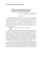
1.1.1 Application
The P150 is a high-speed centrifugal separator
intended for marine and land applications. It is
specifically designed for cleaning of mineral oils
from water and solid particles (sludge). The
cleaned oil is discharged continuously, while the
sludge is discharged at intervals.
The separator handles the following types of
lubricating oils and low viscosity fuel oils:
•
Distillate, viscosity 1,5 - 5,5 cSt/40 °C
•
Marine diesel oil, viscosity 13 cSt/40 °C
•
Intermediate fuel oil and heavy fuel oil
(viscosity 30-380 cSt/50 °C)
•
Lubricating oil of R & O type, detergent or
steam turbine.
The separator can be operated either as a
purifier or as a clarifier. When operated as a
purifier the separator discharges the separated
water continuously.
When the oil contains only small amounts of
water the separator is operated as a clarifier,
discharging the water together with the solid
particles.
The separator has to be installed together with
devices for control of its operation.
D
A
N
G
ER
!
Disintegration hazards
Use the separator only for the purpose and
parameters (type of liquid, rotational speed,
temperature, density etc.) specified in chapter
4
Technical Reference, page 92
and in the Purchase
Order documents.
Consult your Alfa Laval representative before any
changes outside these parameters are made.
G0464881
The P150 separator.
1 SEPARATOR BASICS PURIFIER UNIT 150 SERVICE MANUAL
2
1810664-02
1.1.2 Design
The P150 separator comprises a frame consisting
of the frame lower part, the intermediate part
and the frame top part with a frame hood.
The separator bowl (C) is driven by an electric
motor (A) via a flat-belt power transmission (D)
and bowl spindle (B). The motor drive is
equipped with a friction coupling to prevent
overload.
The bowl is of disc type and hydraulically
operated at sludge discharges. The hollow bowl
spindle (B) features an impeller which pumps
closing water from a built-in tank to the
operating system for sludge discharge.
The main inlets and outlets are shown with their
connection numbers in the illustration. The
connections are listed in chapter 4 Technical
Reference, page 92, where also the basic size
drawing can be found.
1.1.3 Outline of function
The separation process takes place in the
rotating bowl. Unseparated oil is fed into the
bowl through the inlet (201). The oil is cleaned in
the bowl and leaves the separator through the
outlet (220) via a paring chamber.
Impurities heavier than the oil are collected in
the sludge space at the bowl periphery and
removed automatically at regular intervals.
Permissible pressures and operating conditions
are specified in chapter 4 Technical Reference,
page 92.
The processing parts of the separator are shown
in the illustration on next page.
There are no contacting surfaces between
process rotating parts (the bowl) and stationary
parts (inlet, outlet, feed devices), and the
interfacing surfaces are not sealed. As the
separation process is carefully balanced
regarding pressures and fluid levels, any
leakages will not occur as long as the correct
running conditions are maintained.
G0739541
Sectional view
Main parts, inlets and outlets
A Electric motor
B Bowl spindle
CBowl
DFlat belt
E Closing water tank
201 Oil inlet
220 Oil outlet
221, 222 Water/sludge outlet
372 Opening water inlet
373 Bowl closing water
377 Overflow
462 Drain
463 Drain
1810664-02
3
PURIFIER UNIT 150 SERVICE MANUAL 1 SEPARATOR BASICS
1.1.4 Separating function
Liquid flow
Separation takes place in the separator bowl to
which unseparated oil is fed through the inlet
pipe (201). The oil is led by the distributor (T)
towards the periphery of the bowl.
When the unseparated oil reaches the slots of
the distributor, it will rise through the channels
formed by the disc stack (G) where it is evenly
distributed into the disc stack.
The oil is continuously separated from water and
sludge as it will flow towards the center of the
bowl. When the cleaned oil leaves the disc stack
it rises upwards and enters the paring chamber.
From there it is pumped by the paring disc (F)
and leaves the bowl through the outlet (220).
Separated sludge and water move towards the
bowl periphery. In purification separated water
rises along the outside of the disc stack, passes
from the top disc channels over the edge of the
gravity disc (K) and leaves the bowl into the
common sludge and water outlet (221) of the
separator.
Heavier impurities are collected in the sludge
space (H) outside the disc stack and are
discharged at intervals through the sludge ports
(L).
G0112361
F Paring disc
G Disc stack
H Sludge space
I Top disc
K Gravity disc
L Sludge ports
R Bowl body
S Bowl hood
T Distributor
U Paring chamber cover
201 Oil inlet
206 Water seal and
displacement water
inlet
220 Oil outlet
221 Water outlet
372 Opening water inlet
373 Bowl closing water
377 Overflow
1 SEPARATOR BASICS PURIFIER UNIT 150 SERVICE MANUAL
4
1810664-02
Water seal in purification
To prevent the oil from passing the outer edge of
the top disc (I) and escaping through the water
outlet (221), a water seal must be provided in the
bowl. This is done by filling the bowl with water
through the water inlet (206), before
unseparated oil is supplied. When oil feed is
turned on the oil will force the water towards the
bowl periphery and an interface (X) is formed
between the water and the oil. The position of
the interface is determined by the inner
diameter of gravity disc (K).
Displacement of oil
To avoid oil losses at sludge discharge,
displacement water is fed to the bowl.
Prior to a discharge the oil feed is stopped and
displacement water added through the water
inlet (206). This water changes the balance in
the bowl and the interface (X) moves inwards to
a new position (Y), increasing the water volume
in the sludge space. When the sludge discharge
takes place sludge and water alone are
discharged.
Sludge discharge occurs while the displacement
water is still flowing. A new water seal will
therefore establish immediately afterwards. The
oil feed is then turned on again.
Gravity disc
In the purification mode, the position of the
interface (X) can be adjusted by replacing the
gravity disc (K) for one with larger or smaller
diameter.
A gravity disc with a larger hole will move the
interface towards the bowl periphery, whereas a
disc with a smaller hole will place it closer to the
bowl centre.
The correct gravity disc is selected from a
nomogram, see 4.7.4 Gravity disc nomogram,
page 116.
G0112371
Principle of liquid seal and
displacement water in purification
H Sludge space
I Top disc
K Gravity disc
X Normal interface position
Y Interface position just before
discharge
206 Water inlet
221 Water outlet
1810664-02
5
PURIFIER UNIT 150 SERVICE MANUAL 1 SEPARATOR BASICS
Clarifier disc
In the clarification mode, the gravity disc is
replaced by a clarifier disc which seals off the
water outlet. In this case no water seal is
required and consequently there is no oil/water
interface in the bowl. The clarifier disc is an
optional disc with a hole diameter of 40 mm.
This disc is not shown in the nomograms.
1.1.5 Sludge discharge function
Sludge is discharged through a number of ports
(L) in the bowl wall. Between discharges these
ports are covered by the sliding bowl bottom (M),
which forms an internal bottom in the
separating space of the bowl. The sliding bowl
bottom is pressed upwards against a sealing ring
(m) by force of the closing water underneath.
The sliding bowl bottom is operated
hydraulically by means of operating water
supplied to the discharge mechanism from an
external freshwater line. Opening water is
supplied directly to the operating system in the
bowl while closing water is supplied to the built-
in closing water tank, and pumped to the
operating system through the bowl spindle.
The opening and closing only takes a fraction of
a second, therefore the discharge volume is
limited to a certain percentage of the bowl
volume. This action is achieved by the closing
water filling space above the upper distributor
ring and pushing the sliding bowl bottom
upwards. Simultaneously, the water in the
chamber below the operating slide is drained off
through the nozzles in the bowl body.
G0112371
Sludge discharge mechanism
L Sludge ports
M Sliding bowl bottom
m Sealing ring
N Upper distributing ring
O Operating slide
P Lower distributing ring
R Bowl body
1 SEPARATOR BASICS PURIFIER UNIT 150 SERVICE MANUAL
6
1810664-02
Bowl opening
The key event to start a sludge discharge is the
downward movement of the operating slide. This
is accomplished by supply of opening water (372)
to the discharge mechanism. Water is drained off
through nozzles (Y) in the bowl body. The sliding
bowl bottom is rapidly pressed downwards by
the force from the liquid in the bowl, opening the
sludge ports.
Bowl closing
After the sludge is discharged the sliding bowl
bottom is immediately pressed up and the sludge
ports in the bowl wall are closed.
G0112521
Supply of opening water and closing water
372 Opening water
B Closing and make-up water through
bowl spindle
YNozzles
1810664-02
7
PURIFIER UNIT 150 SERVICE MANUAL 1 SEPARATOR BASICS
1.1.6 Power transmission
Bowl spindle
In addition to its primary role in the power
transmission system, the bowl spindle also
serves as:
•
pump for the closing water
•
supply pipe for the closing water
•
lubricator for spindle ball bearings.
Closing water is pumped through the hollow
spindle (B) to the discharge mechanism in the
bowl. For this purpose a pump sleeve (b4) is
fitted in the lower end.
The two spindle bearings are lubricated with oil
mist. An oil pump (b3) creates the oil mist, which
is sucked through the upper ball bearing by a fan
(b1). Oil is supplied via an oil filling device,
which also serves as a level indicator.
Two identical ring-shaped rubber buffers (b2)
support the top bearing housing. The buffers are
held in place by a buffer holder and form
channels through which the recirculated oil
passes.
Belt drive
The bowl spindle is driven by a flat belt.
Adaptation to 50 or 60 Hz power supply is made
by selecting the motor belt pulley with the
appropriate diameter. A longer belt is needed for
the pulley for 50 Hz.
Correct tension is set by means of a spring-
loaded belt tightener.
Friction coupling
The friction coupling on the motor pulley ensures
gentle start-up and prevents overload of the
electric motor. Centrifugal force creates a torque
that acts on the pulley through the friction
elements.
G0112721
Bowl spindle assembly
BBowl spindle
b1 Fan
b2 Rubber buffers
b3 Oil pump
b4 Sleeve
G0112821
Belt drive
G0112911
Friction coupling
1 SEPARATOR BASICS PURIFIER UNIT 150 SERVICE MANUAL
8
1810664-02
1.1.7 Sensors and indicators
Sight glass
The sight glass shows the oil level in the oil
sump.
Vibration switch (option)
The vibration switch, properly adjusted, trips on
a relative increase in vibration.
The vibration switch is sensitive to vibration in a
direction perpendicular to its base. It contains a
vibration detecting mechanism that actuates a
snap-action switch when the selected level of
vibration is exceeded. After the switch has
tripped it must be reset manually by pressing
the button on the switch.
S0009411G0548421
Reset push button on vibration switch
1810664-02
9
PURIFIER UNIT 150 SERVICE MANUAL 1 SEPARATOR BASICS
1.2 Definitions
Back pressure Pressure in the separator outlet.
Clarification Liquid/solids separation with the intention of separating
particles, normally solids, from a liquid having a lower
density than the particles.
Clarifier disc An optional disc, which replaces the gravity disc in the
separator bowl, in the case of clarifier operation. The disc
seals off the heavy phase outlet in the bowl, thus no liquid
seal exists.
Counter pressure See Back pressure.
Density
Mass per volume unit. Expressed in kg/m
3
at a specified
temperature, normally at 15 °C.
Gravity disc Disc in the bowl hood for positioning the interface between
the disc stack and the outer edge of the top disc. This disc
is only used in purifier mode.
Interface Boundary layer between the heavy phase (water) and the
light phase (oil) in a separator bowl.
Intermediate
Service (IS)
Overhaul of separator bowl and inlet/outlet. Renewal of
seals in bowl and inlet/outlet.
Major Service (MS) Overhaul of the complete separator, including bottom part
(and activities included in an Intermediate Service).
Renewal of seals and bearings in bottom part.
Phase Light phase: the lighter liquid separated, e.g. oil.
Heavy phase: the heavier liquid separated, e.g. water.
Purification Liquid/liquid/solids separation with the intention of
separating two intermixed and mutually insoluble liquid
phases of different densities. Solids having a higher density
than the liquids can be removed at the same time. The
lighter liquid phase, which is the major part of the mixture,
shall be purified as far as possible.
Sediment (sludge) Solids separated from a liquid.
Sludge discharge Ejection of sludge from the separator bowl.
Throughput The feed of process liquid to the separator per time unit.
Expressed in m
3
/hour or litres/hour.
Viscosity Fluid resistance against movement. Normally expressed in
centistoke
(cSt = mm
2
/s), at a specified temperature.
Water seal Water in the solids space of the separator bowl to prevent
the light phase (oil) from leaving the bowl through the
heavy phase (water) outlet, in purifier mode.
10
1810664-02
2 SERVICE INSTRUCTIONS PURIFIER UNIT 150 SERVICE MANUAL
2 Service Instructions
2.1 Periodic maintenance
2.1.1 Introduction
Periodic, preventive maintenance reduces the
risk of unexpected stoppages and breakdowns.
Maintenance logs are shown on the following
pages in order to facilitate periodic maintenance.
D
A
N
G
E
R
!
Disintegration hazards
Separator parts that are worn beyond their safe limits
or incorrectly assembled may cause severe damage
or fatal injury.
2.1.2 Maintenance intervals
The following directions for periodic
maintenance give a brief description of which
parts to clean, check and renew at different
maintenance intervals.
The service logs for each maintenance interval
later in this chapter give detailed enumeration of
the checks that must be done.
Daily checks consist of simple check points to
carry out for detecting abnormal operating
conditions.
Oil change interval is 1500 hours. If the total
number of operating hours is less than 1500
hours change oil at least once every year.
Time of operation between oil changes can be
extended from the normal 1500 hours to 2000
hours if a synthetic oil of group D is used.
In seasonal operation change the oil before a new
period.
1810664-02
11
PURIFIER UNIT 150 SERVICE MANUAL 2 SERVICE INSTRUCTIONS
IS - Intermediate Service consists of an
overhaul of the separator bowl, inlet and outlet
every 3 months or 2000 operating hours. Seals in
bowl and gaskets in the inlet/outlet device and
operating device are renewed.
MS - Major Service consists of an overhaul of
the complete separator every 12 months or 8000
operating hours. An Intermediate Service is
performed, and the flat belt, friction elements,
seals and bearings in the bottom part are
renewed.
3-year service consists of service of the coupling
bearings, service of frame intermediate part and
renewal of frame feet. The rubber feet get harder
with increased use and age.
Other
Check and prelubricate spindle bearings of
separators which have been out of service for 6
months or longer. See also 2.10.2 Before shut-
downs, page 42.
N
O
T
E
Do not interchange bowl parts!
To prevent mixing of parts, e.g. in an installation
comprising several machines of the same type, the
major bowl parts carry the machine manufacturing
number or its last three digits.
2nd year
Oil change
Intermediate Service = IS
Major Service = MS
Service schedule
Installation
1st year
MS
MS
3-year
Service
MS
MS
IS
IS IS
IS IS
IS IS IS
IS
IS IS
IS IS
IS IS IS
3-year Service
2 SERVICE INSTRUCTIONS PURIFIER UNIT 150 SERVICE MANUAL
12
1810664-02
2.1.3 Maintenance procedure
At each intermediate and major service, take a
copy of the service log and use it for notations
during the service.
An intermediate and major service should be
carried out in the following manner:
1
Dismantle the parts as mentioned in the
service log and described in chapter
3
Dismantling/Assembly, page 43
.
Place the separator parts on clean, soft
surfaces such as pallets.
2
Inspect and clean the dismantled separator
parts according to the service log.
3
Fit all the parts delivered in the service kit
while assembling the separator as described
in chapter
3 Dismantling/Assembly, page 43
.
The assembly instructions have references to
check points which should be carried out
during the assembly.
2.1.4 Service kits
.
Special service kits are available for
Intermediate Service (IS) and Major Service
(MS).
For other services the spare parts have to be
ordered separately.
Note that the parts for IS are not included in the
MS kit.
The contents of the service kits are described in
the Spare Parts Catalogue.
N
O
TE
Always use Alfa Laval genuine parts as otherwise the
warranty will become invalid.
Alfa Laval takes no responsibility for the safe
operation of the equipment if non-genuine spare
parts are used.
S0021031
Spare parts kits are available for
Intermediate Service and Major Service
1810664-02
13
PURIFIER UNIT 150 SERVICE MANUAL 2 SERVICE INSTRUCTIONS
2.2 Maintenance Logs
2.2.1 Daily checks
The following steps should be carried out daily.
2.2.2 Oil change - monthly
The oil change and check of belt transmission
should be carried out every 1500 hours of
operation.
When using a group D oil, time of operation
between oil changes can be extended from the
normal 1500 hours to 2000 hours.
When the separator is run for short periods, the
lubricating oil must be changed every 12 months
even if the total number of operating hours is
less than 1500 hours (less than 2000 hours if a
group D oil is used).
See chapter 4.6 Lubricants, page 103 for further
information on oil brands etc.
Main component and activity Part Page Notes
Inlet and outlet
Check for leakage Connecting housing
-
Separator bowl
Check for vibration and noise
-
Belt transmission
Check for vibration and noise
-
Oil sump
Check Oil level
-
Electrical motor
Check for vibration, heat and
noise
See manufacturer’s instructions
Main component and activity Part Page Notes
Bowl spindle and transmission
Check Belt tension
83
Change Oil in oil sump
35
2 SERVICE INSTRUCTIONS PURIFIER UNIT 150 SERVICE MANUAL
14
1810664-02
2.2.3 IS - Intermediate Service
Name of plant: Local identification:
Separator: P150 Manufacture No./Year:
Total running hours: Product No.: 881100-03-01
Date: Signature:
Renew all parts included in the Intermediate Service kit (IS) and do the following activities.
Main component and activity Part Page Notes
Inlet and outlet, frame
Clean and inspect Threads of inlet pipe
24
Paring disc
24
Housings and frame hood
-
Separator bowl
Clean and inspect Bowl hood
25
Top disc
34
Bowl discs
34
Distributor
-
Nozzles in bowl body
21
Sliding bowl bottom
21
Discharge mechanism
21
Threads on bowl hood and
bowl body
25
Bowl spindle cone and bowl
body nave
24
Check Disc stack pressure
27
Galling of guide surface
25
Corrosion, erosion, cracks
17 - 19
Power transmission
Check Belt and belt tension
83
Change Oil in oil sump
35
Electrical motor
Lubrication (if nipples are fitted) See sign on motor
-
Signs and labels on separator
Check attachment and legibility Safety label on hood
114
Other plates and labels
114
1810664-02
15
PURIFIER UNIT 150 SERVICE MANUAL 2 SERVICE INSTRUCTIONS
2.2.4 MS - Major Service
Name of plant: Local identification:
Separator: P150 Manufacture No./Year:
Total running hours: Product No.: 881100-03-01
Date: Signature:
Renew all parts included in the Intermediate and Major Service kits and do the following
activities.
Main component and activity Part Page Notes
Inlet and outlet, frame
Clean and inspect Threads of inlet pipe
24
Paring disc
24
Housings and frame hood
-
Separator bowl
Clean and inspect Bowl hood
25
Top disc
34
Bowl discs
34
Distributor
–
Nozzles in bowl body
21
Sliding bowl bottom
21
Discharge mechanism
21
Threads on bowl hood and
bowl body
25
Bowl spindle cone and bowl
body nave
24
Check Height of paring disc
28
Disc stack pressure
27
Galling of guide surface
25
Corrosion, erosion, cracks
17 - 19
2 SERVICE INSTRUCTIONS PURIFIER UNIT 150 SERVICE MANUAL
16
1810664-02
Vertical driving device
Clean and inspect Oil mist fan
66
Oil pump
66
Water tank
89
Pump sleeve
Bowl spindle
63
Ball bearing housing
indentations
63
Check Radial wobble of bowl spindle
29
Oil sump
Clean Oil sump
35
Change Oil
35
Clean and inspect Oil filling device
88
Friction coupling
Clean and inspect Friction coupling
77
Electrical motor
Replace
Bearings
1)
Signs and labels on separator
Check attachment and legibility Safety label on hood
114
Other signs and labels
114
1)
See manufacturer’s instructions.
Main component and activity Part Page Notes
1810664-02
17
PURIFIER UNIT 150 SERVICE MANUAL 2 SERVICE INSTRUCTIONS
2.3 Check points at
Intermediate Service
2.3.1 Corrosion
Non-stainless steel and cast iron parts
Corrosion (rusting) can occur on unprotected
surfaces of non-stainless steel and cast iron.
Frame parts can corrode when exposed to an
aggressive environment.
Evidence of corrosion attacks should be looked
for and rectified each time the separator is
dismantled. Main bowl parts such as the bowl
body and hood must be inspected with particular
care for corrosion damage.
D
A
N
G
E
R
!
Disintegration hazard
Inspect regularly for corrosion damage. Inspect
frequently if the process liquid is corrosive.
Always contact your Alfa Laval representative if
you suspect that the largest depth of a corrosion
damage exceeds 1,0 mm or if cracks have been
found. Do not continue to use the separator until
it has been inspected and given clearance for
operation by Alfa Laval.
Cracks or damage forming a line should be
considered as being particularly hazardous.
G0172111
Main bowl parts to check for corrosion
2 SERVICE INSTRUCTIONS PURIFIER UNIT 150 SERVICE MANUAL
18
1810664-02
Stainless steel
Other metal parts
Separator parts made of materials other than
steel, such as brass or other copper alloys, can
also be damaged by corrosion when exposed to
an aggressive environment. Possible corrosion
damage can be in the form of pits and/or cracks.
Stainless steel parts corrode when in contact
with either chlorides or acidic solutions. Acidic
solutions cause a general corrosion. The chloride
corrosion is characterised by local damage such
as pitting, grooves or cracks. The risk of chloride
corrosion is higher if the surface is
•
exposed to a stationary solution,
•
in a crevice,
•
covered by deposits,
•
exposed to a solution that has a low pH value.
A corrosion damage caused by chlorides on
stainless steel begins as small dark spots that
can be difficult to detect.
•
Inspect closely for all types of damage by
corrosion and record these observations
carefully.
•
Polish dark-coloured spots and other
corrosion marks with a fine grain emery cloth.
This may prevent further damage.
D
A
N
G
E
R
!
Disintegration hazard
Pits and spots forming a line may indicate cracks
beneath the surface.
All forms of cracks are a potential danger and are
totally unacceptable.
Replace the part if corrosion can be suspected of
affecting its strength or function.
S0020611
Example of chloride corrosion in
stainless steel.
S0020511
Polish corrosion marks to prevent
further damage.
1810664-02
19
PURIFIER UNIT 150 SERVICE MANUAL 2 SERVICE INSTRUCTIONS
2.3.2 Erosion
Erosion can occur when particles suspended in
the process liquid slide along or strike against a
surface. Erosion can become intensified locally
by flows of higher velocity.
D
A
N
G
E
R
!
Disintegration hazard
Inspect regularly for erosion damage. Inspect
frequently if the process liquid is erosive.
Always contact your Alfa Laval representative if
the largest depth of any erosion damage exceeds
1,0 mm. Valuable information as to the nature of
the damage can be recorded using photographs,
plaster impressions or hammered-in lead.
Erosion is characterised by:
•
Burnished traces in the material.
•
Dents and pits having a granular and shiny
surface.
Parts of the bowl particularly subjected to
erosion are:
•
The paring disc.
•
The top disc.
•
The underside of the distributor in the vicinity
of the distribution holes and wings.
•
The sludge ports.
Look carefully for any signs of erosion damage.
Erosion damage can deepen rapidly and
consequently weaken parts by reducing the
thickness of the metal.
G0205221
Maximum permitted erosion.
2 SERVICE INSTRUCTIONS PURIFIER UNIT 150 SERVICE MANUAL
20
1810664-02
2.3.3 Cracks
Cracks can initiate on the machine after a period
of operation and propagate with time.
•
Cracks often initiate in areas exposed to high
cyclic material stresses. These cracks are
called fatigue cracks.
•
Cracks can also initiate due to corrosion in an
aggressive environment.
•
Although very unlikely, cracks may also occur
due to the low temperature embrittlement of
certain materials.
The combination of an aggressive environment
and cyclic stresses will speed-up the formation of
cracks. Keeping the machine and its parts clean
and free from deposits will help to prevent
corrosion attacks.
D
A
N
G
E
R
!
Disintegration hazard
All forms of cracks are potentially dangerous as they
reduce the strength and functional ability of
components.
Always replace a part if cracks are present
It is particularly important to inspect for cracks
in rotating parts.
Always contact your Alfa Laval representative if
you suspect that the largest depth of the damage
exceeds 1,0 mm. Do not continue to use the
separator until it has been inspected and cleared
for operation by Alfa Laval.
1810664-02
21
PURIFIER UNIT 150 SERVICE MANUAL 2 SERVICE INSTRUCTIONS
2.3.4 Discharge mechanism
2.3.5 Bowl hood and sliding bowl
bottom
Dirt and lime deposits in the sludge discharge
mechanism can cause discharge malfunction or
no discharge.
•
Thoroughly clean and inspect the parts. Pay
special attention to important surfaces (1, 2, 3
and 4). If necessary, polish with steel wool.
•
Clean nozzles (5) using soft iron wire or
similar. Note that lime deposits can with
advantage be dissolved in a 10% acetic acid
solution.
Use Loctite 242 on the threads if the nozzles
have been removed or replaced.
Poor sealing between the bowl hood seal ring and
the edge of the sliding bowl bottom will cause a
leakage of process liquid from the bowl.
G0121511G0071031
A Sealing surface in the bowl between bowl
hood and sliding bowl bottom.