SIGTTO an introduction to the design and maintenance of cargo system pressure relief valves on board gas carriers 2nd edition september 1998ISBN 1 85609 163 5
Bạn đang xem bản rút gọn của tài liệu. Xem và tải ngay bản đầy đủ của tài liệu tại đây (1.62 MB, 35 trang )
An Introduction to the Design and Maintenance
of Cargo System Pressure Relief Valves
on Board Gas Carriers
First Published in 1994 by:
© Society of International Gas Tanker and Terminal Operators Ltd
Fully Revised and Updated in February 1998
Printed and Distributed by
WITHERBY& CO LTD
32-36 Ay/esbury Street, London EC1R OET
Telephone:- 44 (0)171 253 5413 Fax:- 44 (0)171 251 1296
ISBN:- 1 85609 163 5
2nd Edition September 1998
Contents
Page No,
1. Introduction
1
2. Requirements for Pressure Relief Valves
1
2.1
2.2
2.3
General
Valve design requirements
Design and installation
3. Types of Pressure Relief Valves
5
3.1
Pilot operated valves
5
3.2
Spring operated pressure relief valves
7
4. Preventative and Planned Maintenance Procedures for Pressure Relief Valves
8
4.1
Scope
8
4.2
4.3
4.4
4.5
4.6
Pressure relief valve preventative maintenance philosophy
Pressure relief valve preventative maintenance frequency
Pressure relief valve maintenance and inspection
Maintenance and care of diaphragms
Spare parts
9
9
9
11
11
5. Emergency Closure of Pressure Relief Valves
5.1
Emergency closure
6. Operating Problems and Faults
7.
1
2
3
11
12
13
6.1
6.2
Operating problems
Faults
13
13
6.3
Chloride stress corrosion cracking
14
In-Service Testing
19
Appendix 1:
IMO IGC Code - Extracts from Chapter 8 Cargo Tank Vent Systems.
21
Appendix 2:
Definitions and Terminology Used in Regard to Pressure Relief Valves.
29
Appendix 3:
Metal to Metal Seat Valves - Precautions and Hints for Lapping Seats.
29
Appendix 4:
Pressure Levels
31
Appendix 5:
Fire Activated Pressure Relief Systems
33
References
September 1998
34
Hi
;
SIGTTO ______________________________________________________________________
1.
INTRODUCTION
In 1992, an incident involving relief valve failure occurred during the loading of a semi-pressurised LPG
carrier. The cargo being loaded was propane and the pressure relief valves (PRVs) were set to operate
at 11 bar gauge. During the final stages of loading and at a pressure of only 7 bar gauge, one of the
two pressure relief valves fitted to a cargo tank lifted and failed to re-seat.
There were no guidelines available on board, or at the terminal, to describe, or suggest, emergency
methods of closing the valve.
Eventually, the valve was physically blanked off with the tank pressure reduced to 0.02 bar gauge; by
which time a large quantity of product was lost to the atmosphere. Subsequent investigation of the
valve indicated that there had been failures of the pilot valve diaphragms. These failures were believed
to have occurred because the diaphragms had been in service for too long. Luckily, the product did
not ignite and the only loss was commercial. Had the cargo been ammonia or VCM and the wind
direction blown this towards a densely populated area, the consequences could have been fatal.
Application of gas or nitrogen, at cargo tank pressure, to the top of the main valve dome would have
closed the valve and considerably limited the amount of propane released to the atmosphere.
Unfortunately the crew were not aware of this simple procedure.
A similar incident occurred the same year, in the Far East, when a fully pressurised LPG carrier had a
relief valve failure. This also resulted in a large vapour cloud enveloping the jetty area. Investigation
showed that the cause of the problem was lack of maintenance.
As a result of these and some other similar incidents, SIGTTO produced "Guidelines on the
Maintenance of Pressure Relief on board Gas Carriers". In 1998 this booklet was revised and expanded
and the title changed to: "An Introduction to the Design and Maintenance of Cargo System
Pressure Relief Valves on Board Gas Carriers".
It must be stressed that this publication is a general guide to ship's staff and not intended
to replace manufacturers instruction manuals. Furthermore it is recommended that ship's staff
responsible for the maintenance of these valves attend a manufacturers training course. It is also hoped
that the book may be of use to officers studying for certificates of competency.
For further information on the inspection and maintenance of pressure relief valves, API Recommended
Practice 576 - Inspection of Pressure Relieving Devices, is thoroughly recommended.
The SIGTTO Secretariat would like to acknowledge the personal assistance given by members of the
Society and the Safety Relief Valve Industry in the production of this book.
2.
REQUIREMENTS FOR PRESSURE RELIEF VALVES
2.1
General
The International Maritime Organization (IMO) Codes for Gas Carriers (see Appendix 1) requires at least
two pressure relief valves of equal capacity to be fitted to any cargo tank with a volume greater than
20 m3. Below 20 m3 one pressure relief valve is sufficient. The types of valves normally fitted are either
spring-loaded or pilot-operated relief valves. Pilot-operated relief valves may be found on Types A, B
and C tanks while spring-loaded relief valves are usually only used on Type C tanks and pipe-work.
The maximum allowable pressure in the vapour space of type 'A' tanks and prismatic Type B tanks is
0.7 barg. The Kvaerner Moss spherical Type B tanks can operate at the slightly higher pressure of 1.9
barg. However, the normal operating pressure for both Type A and Type B tanks is generally 0.25 barg.
Type C tanks are pressure vessels and are generally designed to operate at pressures up to 18 barg.
September 1998
1
_______________________________________________________________________ SIGTTO
The use of pilot-operated relief valves on Type A and B tanks ensures accurate operation at the low
pressure conditions prevailing; while their use on Type C tanks, for example, allows variable relief
settings to be achieved using the same valve. This may be done by changing the pilot spring or, more
usually, by fitting one or more auxiliary(or complimentary) setters. Figures 1a and 1b show typical pilot
operated relief valves. Other types of pilot valve are available for adjustment of "set pressure" and
"blow-down pressure".
Pilot operated relief valves with adjustable settings may be provided for two reasons. Firstly, they may
be used to provide a higher set pressure than normal, but not exceeding the Maximum Allowable Relief
Valve Setting (MARVS), during cargo handling (sometimes referred to as "harbour" setting). Secondly,
they can improve the loading limits of type 'C' tanks. By causing relief valves to lift at pressures below
those required to avoid over-stressing of the tank structure, viz below MARVS, the reference
temperature, used to determine the tank filling limit, can be reduced. This in turn reduces the difference
between reference temperature and loading temperature and consequently reduces the cargo "shut
out" volume. Such adjustment, however, is not necessary on vessels having an "adequate vent system"
under the amendments to the IGC and GC cases (8.2.18). Further information on this subject may be
obtained from the SIGTTO/IACS publication; "Application of Amendments to Gas Carrier Codes
Concerning Type C Tank Loading Limits". A further use of adjustable relief valves is if a Type B spherical
tank has to be discharged, in an emergency, by pressurisation. Auxiliary setters are fitted to the pilot
valve to ensure tank pressure does not exceed the design pressure.
Whenever such valves are used for more than one pressure setting, a proper record must be kept of
any changes in the pilot valve springs with the pilot assembly cap always being resealed after such
changes. A record must also be kept of the use of auxiliary setters. Ideally a dedicated cupboard,
should be mounted in the Cargo Control Room.
When pressure settings are changed the tank high pressure alarms should be adjusted accordingly.
Cargo tank pressure relief valves relieve into one or more vent stacks. Vent stack drains are provided
and should be checked regularly, to ensure no accumulation of rain water etc., in the stack.
Accumulation of liquid can have the effect of altering the pressure relief valve setting due to the resulting
increased back pressure from the vaporising liquid, or frozen water. This may prevent the valve lifting
at its set pressure, or in the case of a pilot operated relief valve the valve may open and have reverse
flow if the pressure in the vent line exceeds the cargo tank pressure. The use of a back-flow preventer
will prevent a pilot operated relief valve from opening due to back-pressure in the vapour column.
However, should a head of liquid accumulate in the vent riser of a diaphragm operated valve it may
provide sufficient pressure to the underside of the diaphragm to overcome tank pressure on the top of
the diaphragm and allow the valve to open.
The IMO Codes require all pipelines, or components which may be isolated when full of liquid, to be
provided with relief valves to allow for thermal expansion of the liquid. These valves, often referred to
as "thermal relief valves", can relieve either into the cargo tanks themselves or, alternatively, they may
be taken to a vent stack via liquid collecting pots with, in some cases, level switch alarm and a liquid
vaporising source.
2.2
Basic Requirements
Pressure relief valve design must take account of two basic requirements. These are accidental overpressurisation and accidental over-heating of the tank contents.
Over-pressurisation must be prevented, while keeping the amount of gas discharged through the
pressure relief valve to a minimum; for reasons of environmental protection and economy. The valve
must therefore be designed to shut off at a pressure just below its opening pressure, once the overpressurisation has been relieved.
Accidental over-heating will result in vaporisation of the liquid and increased pressure which can only
be safely reduced by discharge of gas through the pressure relief valve. The Classification Societies
2
September 1998
SIGTTQ ________________________________________________________________________________
have defined tank design rules which fixes the amount of gas to be discharged as a function of the
liquid volume in the tank, the dimensions of the tank and the thermal insulation of the tank. The rules
create a requirement for high gas flow rates.
Pressure relief valves are therefore principally designed to take account of the following requirements:
a)
To provide an effective seal until the pre-set opening pressure (set pressure) is reached.
b)
A precise and clean release of gas is achieved irrespective of cargo temperature.
c)
Complete opening of the valve to give full flow.
d)
Complete closing of the valves at a pressure slightly below the opening pressure. This is
normally 3%-7% of opening pressure, but in the case of diaphragm valves operating at
pressures of less than 100 mbar this range is extended to more practical limits, in the order of
10 to 15%.
e)
Operation to be free from the effects of frosting which may occur within the valve.
0
Operation to be unaffected by acceleration due to movement of the ship in a seaway, or list or
trim.
g)
The valve must repeatedly open at the prescribed set pressure, (see App I - 8.2.5.)
h)
Back pressure in the vent pipe system does not impede full flow of the valve.
The capacity of a given pressure relief valve is governed by various factors, including pressure,
temperature and the fluid being handled. A general formula for the capacity of a valve is given below
and shows how this is affected by these factors.
2.3
Design and Installation
The sizing of relief valves is stipulated by the various Administrations, based on Chapter 8 of the IGC
Codes and, as such, is beyond the scope of this publication. However, problems in service can often
be alleviated by good pipe-work design and installation practices.
Most manufacturers recommend that each valve has a separate expansion bellows fitted in the vent
line, before joining a common header. Failure to observe this requirement can result in unacceptable
loads being transmitted via the vent lines, due to thermal contraction and expansion. This may impose
undue loads on, or cause malfunction of, the second valve. Pipe-work should always be adequately
supported.
Depending on the grades of stainless steel used in construction, painting, for corrosion prevention, may
or may not be required. Should it be deemed necessary to paint the valves the coatings should be
applied judiciously, as numerous malfunctions of relief valves have been attributable to the blockage of
small orifices by paint and paint flakes.
September 1998
3
SIGTTO _________________________________________________________________________
Supervision during construction of the vessel and re-installation (if removed for overhaul), should ensure
that there is no undue stress imposed on the valves due to poorly fitting pipe-work. Pipe-work should
also be sighted internally for any debris, prior to the fitting of valves.
3.
TYPES OF PRESSURE RELIEF VALVES
3.1
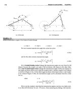
Pilot Operated Pressure Relief Valves (see Figure 2a. 2b and 2c)
A pilot operated pressure relief valve consists of a main valve and a pilot valve. The main valve has an
unbalanced piston or diaphragm (unbalanced member). Tank pressure is applied to the top of the
piston or diaphragm via the pilot. As the area at the top of the piston or diaphragm is larger than the
bottom, the valve remains closed. When the set pressure is reached, the pilot valve opens venting the
space above the piston to atmosphere, or the vent stack. An example of the forces involved in the
operation of a pilot operated valve is given in the description of figure 2c.
:
SIGTTO _________________________________________________________________________
The unbalance of the piston (moving member) usually ranges from 1.2 : 1 to 3.0 : 1. This means
that the area on the top side of the piston is larger than the seating area.
For example, with a 2 : 1 unbalance, the area of the top side is two times that of the seating area. If
the set pressure is 7 bar and the seat area is 12 cm2, then the net forces holding the seat closed,
immediately prior to opening, is 84 kg
Upward force = 12 cm2 x 7 kg/cm2 = 84 kg
Downward force = 2(12 cm2 x 7 kg/cm2) = 168 kg
Therefore net force holding valve shut = 168 - 84 = 84 kg
For the valve to open, the pilot valve must de-pressurise the cavity on the top side of the piston to a
pressure equal to 50% of the inlet pressure. When that occurs, the forces are in balance and the valve
is on the threshold of opening. The piston will then move upwards and the pressure will remain constant
during this period. When the pilot closes the top cavity is re-pressurised and the piston closes.
For simplicity in the above example it has been assumed that 1 bar = 1 kg/cm2.
3.2
Spring Operated Pressure Relief Valves (See Figure 3)
The piston or valve seating is accomplished through the pressure exerted by a coil spring onto the top
of the piston or valve. As the tank pressure increases, so the valve-seating contact force is reduced,
making the setting of an exact set pressure more difficult to accomplish. This is particularly true at low
pressures.
The opening of the valve and the amount of opening is, therefore, dependant on the compression of
the spring. Any pressure, due to flow downstream of the pressure relief valve, will also tend to close
the valve.
______________________________________________________________________ SIGTTO
The operation of the valve and its maintenance is simpler than for the alternative pilot valve type, but it
has the disadvantage that, in general, it cannot be set as accurately, particularly at low pressures.
The different characteristics of the pilot operated and conventional spring loaded pressure relief valves
are shown in Fig.4.
As the force holding the valve to its seat becomes zero at the pre-set opening pressure, the pilot
operated valve lifts completely under the thrust exerted by the gas. Whereas the spring loaded valve
can be raised only by a further increase in pressure, since the compression of the spring requires an
additional force to which must be added the static pressure due to the flow downstream of the valve.
The above diagrams illustrate this graphically.
4.
PREVENTATIVE AND PLANNED MAINTENANCE PROCEDURES FOR
PRESSURE RELIEF VALVES
4.1
Scope
This section is applicable to both pilot operated pressure relief valves and direct spring operated
pressure relief valves used for the protection of cargo tanks, hold spaces, insulation spaces, inter-barrier
spaces and cargo piping. Ship cargo system designs may be fully pressurised, semi-pressurised, or
fully refrigerated. Cargoes contained may be LNG, LPG, chemical gases, or Ammonia. The design of
the tank, such as spherical, membrane, prismatic etc. has no direct consequence to the
recommendations prescribed.
8
September 1998
I
SIGTTO______________________________________________________________________________
I
f
[
I
These guidelines do not specifically address equipment such as boilers, turbines, compressors,
evaporators, pumps, heat exchangers etc. The safety relief valves supplied as part of these systems
should be maintained in accordance with the manufacturer recommendations. These valves are usually
of the spring operated type.
It 4.2
Pressure Relief Valve Preventative Maintenance Philosophy
Under normal operating conditions pressure relief valves should never need to operate. They must not,
however, be forgotten. Regular routine maintenance is essential to ensure that they will function
correctly if required. LP valves, in particular, should be tested to ensure the pallet has not stuck to the
seat.
All personnel involved in the operation of the cargo systems protected by these valves should be familiar
with their function, normal operation and maintenance requirements, as laid down by the manufacturers
and system designers. Operators should also be familiar with any means of closing them in an
emergency.
4.3
Pressure Relief Valve Maintenance Frequency
Table 1 provides a frequency matrix by valve type for various preventative type actions. The
combination of maintenance functions described requires actions by both the ship's crew and repair
yard personnel. They may also require input from the manufacturer or their designated service
representative.
Table 2 provides an action matrix by various valve types which can be applied during time at sea and
also during shipyard overhauls. These actions are specific in nature and are not intended to conflict
with instructions of any particular manufacturer, who should be consulted in case of doubt or
uncertainty.
4.4
Pressure Rrelief Valve Maintenance and Inspection
The following points should be taken into consideration when inspecting and overhauling pressure relief
valves:-
1.
The manufacturers instructions should be followed at all times.
2.
"Pirate" or home made spare parts should not be used. This is particularly true of springs and
diaphragms.
3.
Valves should be handled with care and always transported in the upright position. This is
particularly relevant when being transported from the workshop to ship. So many problems have
been attributable to transit damage that many experienced ship operators now specify that,
whenever possible, the larger pilot operated valves are overhauled in situ. However, when
making this decision consideration should be given to other work being carried out in the vicinity
of these valves and the amount of protection that can be afforded to them during the overhaul.
If the decision is taken to remove valves to a shore workshop, it is imperative that each valve is
tagged and a corresponding tag used to mark the position from which is was taken.
4.
Valves should normally be tested on dry air or nitrogen as this gives an indication of very small
leaks through the bubble tester (figure 5). Should a water test be considered necessary the
valve must be stripped and dried and then checked for seat tightness and set on dry gas. This
is particularly important if it is intended for low temperature service.
5.
When removed for overhaul, a valve should be put on the test rig and popped before
dismantling and the results recorded.
September 1998
9
______________________________________________________________________ SIGTTO
6.
Record sheets should be kept for all valves.
7.
Before removing valves, check cargo records and health and safety data sheets for any possible
decontamination requirements.
8.
Never attempt to lap the valve nozzle to the disc.(see Appendix 3 for maintenance hints for
metal to metal seats)
9.
Accuracy and repeatability of the set pressure will be impossible to achieve if the test rig does
not have sufficient surge volume. This is particularly true with spring operated valves, where
leakage may occur at 90% of set pressure and significant simmer at 95% set pressure. A small
test volume and feed rate may never be able to push the valve past the simmer point and
subsequently the valve will be set at a pressure higher than intended. Therefore it can be seen
that it is not sufficient to connect an air hose to the inlet flange of the valve and test in this
manner.
10. There is no accepted standard for surge tank capacity, but Figure 5 gives a graph of surge
tank volume related to valve orifice area. It is published by the US National Board of Boiler and
Pressure Vessel Inspectors and is generally considered to be very conservative. It can be seen
that a 150 mm NB valve, for example, with an orifice area of 113 cm2 (17.5 in2) and a design
blowdown of 7% would require a surge tank of (133ft3) 8 m3, a facility that few test shops
would have.
An advantage of pilot valves is that they only require a small surge volume (in the order of 10
litres), due to the small capacity of the pilot.
11. When the valve is on the test rig, it should be fitted with a bubble tester (figure 6) to enable the
seat tightness and the exact point at which it starts to lift to be accurately determined. Seat
tightness is generally quoted in bubbles per minute (bpm). For soft seat valves, 0 bpm is the
norm, whereas 30 bpm is common for metal seated valves. These figures generally apply at
90% of set pressure. API Standard 527 gives more information on this subject.
12. Valves should always be overhauled and tested in a clean environment, using clean tools and
trained personnel.
13. The valve discharge nozzle must be positioned to prevent exposure of personnel to a sudden
blast of air, water or other projectiles from the valve. Ear protection may also be required when
testing high pressure valves.
10
September 1998
4.5
Maintenance and Care of Diaphragms
Diaphragm failure, be it main or pilot, will result in the pressure relief valve opening and, at least initially,
an uncontrollable release of cargo. Their cost bears no resemblance to the potential consequences
of
a failure. For this reason alone these items should be examined and renewed at regular intervals. When
determining maintenance intervals consideration should be given to the cargo tank operating pressure
and the aggressiveness of the products being carried. Maintenance intervals may, of course, be
modified in the light of operating experience.
Spare diaphragms, manufactured from PTFE, Cryoflex™ or other synthetic materials, should be stored
flat, in a cool dark place, such as an air-conditioned control room or office. Kept in this manner they
have a shelf life of up to 4 years, before being put into use.
For valves fitted with metallic diaphragms manufacturers instructions on inspection and replacement
should be observed. Generally these will have longer shelf and service lives.
Care should be taken to ensure that the spare diaphragm is fitted the right way up.
A major manufacturer of relief valves for LNG duty, with non metallic diaphragms, suggests that: "all
diaphragms are changed at the vessel's first refit after delivery; due to the wear and tear imposed during
commissioning and testing. Thenceforth, they should be inspected at the next refit and replaced at the
refit following that. This cycle, which assumes the first refit is 24 months after delivery and subsequent
refits at 30 months intervals, should then continue throughout the vessel's life." This suggestion is the
result of a number of years of trouble free operation.
4.6
Spare Parts
It is strongly recommended that at least one complete set of manufacturers recommended spares is
kept onboard the vessel for each type of pressure relief valve fitted.
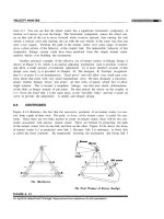
5.
EMERGENCY CLOSURE OF PRESSURE RELIEF VALVES
If a boiler safety valve does not close after operation the result is reduced boiler pressure and
subsequent loss or reduction in power. The failure to close of a pressure relief valve on a gas tank can
result in fire, explosion, or the formation of a toxic plume. For this reason, all senior officers should be
aware of the methods available for the emergency closure of pressure relief valves on their vessel and
the location of tools and equipment required to carry out these operations. It is also strongly
recommended that owners consult with individual manufacturers of the relief valves fitted on their
vessels and incorporate emergency closure procedures into the cargo operations manual.
September 1998
11
_______________________________________________________________________ SIGTTO
Listed below are some methods suggested by various manufacturers:
5.1
Emergency Closure
In an emergency, the main valve can be closed by pressurising the top of the piston. In the case of
the Anderson Greenwood Type 95 valves, it is suggested that a gas pressure equal to the tank
pressure is applied through the close tee (Item 13) via the plug (Item 18) as shown in Figure 7 below.
Key to figure 7.
1.
2.
3.
4.
5.
6.
7.
8.
9.
10.
12
Auxiliary Setting Device
Supply Tubing
Pilot Exhaust Tubing
Pilot Bracket Bolt
Pilot
Pipe Nipple
Field Test Valve
Field Test Plug
Connector
Check Valve
11.
12,
13.
15.
16.
17.
18.
19.
20.
21.
Connector
Connector
Close Tee
Check Valve
Connector
Connector
Pipe Plug
Body Bolt
Lock Washer
Upper Body
22.
23.
24.
25.
26.
27.
28.
29.
30.
Diaphragm
Washer
Spring Pin
Lower Body
Body
Spring
Ball
0-ring
Gasket
September 1998
SIGTTO __________________________________________________________________________
5.2
Direct spring operated valves can generally be closed by fitting a test gag, which applies pressure to
the valve stem, forcing the disk onto the seat.
5.3
In the event of a diaphragm failure on FMC low pressure valves, the temporary remedy depends on
whether the failure is the main or pilot diaphragm.
If the pilot diaphragm fails, blocking off of the pilot valve vent will cause the valve to reseat.
Should the main diaphragm fail, the tank pressure should be dropped to approximately 40% of set
pressure, where the mass of the pallet assembly should cause the valve to close. As a last resort the
tank pressure should be dropped as low as possible and main outlet blocked off,
5.4
It is suggested that suitable spade blanks are kept, in the event that the inlet or outlet lines to
pressure relief valves reguire blanking in an emergency This is not an easy task and should only
be considered as a last resort, after careful planning and preparation.
If this action is undertaken, the position of the blank should be well marked and noted and it
must be removed as soon as possible.
6.
OPERATING PROBLEMS AND FAULTS
6.1
Operating Problems
Chattering: This is generally caused by the volume of the tank or vessel being too small in relation to
the capacity of the PRV. As a result, the process fluid does not have sufficient kinetic energy to hold
the valve open. This is a design problem and would normally be rectified early in the ship's life. However,
it can also be caused by incorrect setting of the blowdown ring (see fig.3) and excessive back-pressure
in the discharge pipe
This problem can also be encountered if valves are placed on a test rig where the volumetric capacity
of the rig is too small for the valve being tested. Excessive chattering will cause serious seat damage
(see 4,4,9.)
Continued Leakage after operation: This is normally the result of dirt being carried over with the
process fluid and becoming trapped between the seating surfaces. The valve will have to be dismantled
and cleaned. It is also possible that the lifting device has been incorrectly fitted
Leakage: This may be the result of the set pressure being too close to the operating pressure. It is
also possible that the spring is damaged, or the wrong spring is fitted and thus it is not possible to
obtain repeatability of the set pressure. Damaged or leaking seals and joints can also be a cause of
seat leakage.
6.2
Faults
A pilot operated relief valve can open and have reverse flow if the pressure in the vent line exceeds the
pressure in the cargo tank This may occur if the discharged fluids vaporise in the mast A back-flow
preventer is provided by some manufacturers to prevent this phenomena occurring.
Vessel's carrying cargoes that require polymerisation inhibitors, such as Butadiene, may encounter
problems with blockage of the sensing tube between the cargo space and the pilot valve.
Bellows assisted relief valves commonly use stainless steel as the bellows material. This is liable to suffer
from chloride pitting, resulting in barely visible holes in the material and consequently leakage or early
lifting of the valve. These bellows should always be inspected very thoroughly at times of overhaul.
Over-enthusiastic application of paint may result in the blockage of small orifices such as bonnet vents.
Upon removal, flakes of paint are likely to find their way into the pipe-work and thus become a potential
cause of trouble at a later date, when the valve is back in service
September 1998
13
______________________________________________________________________ SIGTTO
6.3
Chloride Stress Corrosion Cracking
Certain components in pilot operated safety relief valves have been known to suffer from chloride stress
corrosion cracking. These include; bolts, nuts, tube fittings and caps, It is generally discovered when
the parts fail mechanically during dismantling. The disturbing fact is that these components, in the
normal course of events, would be expected to last the life of the valve.
The cause of this problem is a high concentration of chlorides from sea water, relatively high metal
temperatures (65 deg C ) due to solar radiation and the use of certain grades of austenitic stainless
steel for the valve components.
On one particular vessel all 16 caps on the check valves, used in the pilot valve pipe-work, were found
to have cracks through the whole thickness of the material, emanating from the bolt holes. A seal failure
of this cap would have resulted in the inadvertent opening of the main valve.
In another instance, corrosion was found at the lower end of the pilot valve auxiliary setter extension
rods, the effect of which was to alter the set pressure of the main valve.
It is recommended that these components are inspected during regular maintenance periods and
replaced every 5 years. Fasteners made of Hastelloy C are available for extended service life, but the
cost of these fasteners is approximately 20 times that of 316 stainless steel fasteners.
Table 1: Showing frequency of preventative maintenance actions for various types of
pressure relief valves
September 1998
15
16
September 1998
September 1998
17
18
September 1998
SIGTTO __________________________________________________________________________
7.
IN-SERVICE TESTING
Ship's staff are often reluctant to undertake this operation and when they do it is generally with some
trepidation, particularly if the test results in the main valve actually opening. If the test will result in the
main valve opening, it should only be undertaken after consideration has been given to:- the tank
contents, previous cargo, ship's position and weather conditions. The operation should be properly
planned and carried out under a Permit to Work. At least two people should be in attendance,
appropriate protective clothing i.e. gloves, goggles, boiler-suits, should be worn and communications
with the Officer of the Watch, via hand held VHP radios, established.
Arguably, it is better to discover that a pressure relief valve will not re-seat when at sea, with the wind
across the deck, than in port, in close proximity to a crowded industrial area.
There are generally two types of test that may be carried out:1.
Ensuring the freedom of operation of the main valve.
A simple check is carried out by removing the plug and opening the valve on the upper housing,
thus releasing the pressure above the diaphragm and allowing the valve to open. The opening of
the valve will be audible, at which point the vent valve is shut causing the valve to re-seat, the
plug can then be replaced. This operation should be carried out every three months, particularly
on fully refrigerated tanks, operating at low pressures, where there is a greater chance of valve
seats sticking, due to the low tank pressure .Figure 8 shows the position of the vent valve on an
FMC Safety Relief Valve.
2.
Checking the set pressure and operation of the pilot valve.
This test will indicate the pressure at which the pilot valve operates. This requires a
manufacturer's field test kit, such as that shown in fig 9. This procedure only tests the operation
and set pressure of the pilot valve, the main valve does not open. Typically it would be used
before and after adjustment of the pilot valve. A brief outline of this operation is given below, but
in practice the manufacturer's procedure should be followed.
i. The pilot discharge tube is removed and replaced with a 1,5mm orifice and the test kit
connected to the field test valve.
ii With the metering and vent valve closed, the gas bottle is opened and the regulator set to
about 14 barg.
iii The metering valve is then slowly opened whilst observing the test gauge. The pressure is
raised until there is a sudden and rapid increase of gas flow from the orifice plug fitted to the
pilot discharge. This is the set pressure of the valve.
September 1998
19
SIGTTO______________________________________________________________________________
Appendix 1
IMO IGC CODE - EXTRACTS FROM CHAPTER 8 - CARGO TANK VENT SYSTEMS
8.1
General
All cargo tanks should be provided with a pressure relief system appropriate to the design of the cargo
containment system and the cargo being carried. Hold spaces, inter-barrier spaces and cargo piping
which may be subject to pressures beyond their design capabilities should also be provided with a
suitable pressure relief system. The pressure relief system should be connected to a vent piping system
so designed as to minimise the possibility of cargo vapour accumulating on the decks, or entering
accommodation spaces, service spaces, control stations and machinery spaces, or other spaces where
it may create a dangerous condition. Pressure control systems specified by chapter 7 should be
independent of the pressure relief systems.
8.2
Pressure Relief Systems
8.2.1 Each cargo tank with a volume exceeding 20 m3 should be fitted with at least two pressure relief
valves of approximately equal capacity, suitably designed and constructed for the prescribed service.
For cargo tanks with a volume not exceeding 20 m3, a single relief valve may be fitted.
8.2.2 Interbarrier spaces should be provided with pressure relief devices complying with recognised
standards.
8.2.3 In general, the setting of the pressure relief valves should not be higher than the vapour pressure
which has been used in the design of the tank. However, where two or more pressure relief valves are
fitted, valves comprising not more than 50% of the total relieving capacity may be set at a pressure up
to 5% above MARVS.
8.2.4 Pressure relief valves should be connected to the highest part of the cargo tank above deck level.
Pressure relief valves on cargo tanks with a design temperature below 0°C should be arranged to
prevent their becoming inoperative due to ice formation when they are closed. Due consideration should
be given to the construction and arrangement of pressure relief valves on cargo tanks subject to low
ambient temperatures.
"Valves should be constructed of materials with a melting point above 925°C. Consideration should be
given to lower melting point materials for internal parts and seals if their use will yield a significant
improvement in the general operation of the valve".
8.2.5 Pressure relief valves should be prototype tested to ensure that the valves have the capacity
required. Each valve should be tested to ensure that it opens at the prescribed pressure setting with
an allowance not exceeding ± 10% for 0 to 1.5 bar, ± 6% for 1.5 to 3.0 bar, ± 3% for 3.0 bar and
above. Pressure relief valves should be set and sealed by a competent authority acceptable to the
Administration and a record of this action, including the values of set pressure, should be retained
aboard the ship.
8.2.6 In the case of cargo tanks permitted to have more than one relief valve setting this may be
accomplished by:
1.
installing two or more properly set and sealed valves and providing means as necessary for
isolating the valves not in use from the cargo tank; or
2.
installing relief valves whose settings may be changed by the insertion of previously approved
spacer pieces or alternative springs or by other similar means not requiring pressure testing
to verify the new set pressure. All other valve adjustments should be sealed.
September 1998
21
______________________________________________________________________ SIGTTO
8.2.7 The changing of the set pressure under the provisions of 8.2.6 should be carried out under the
supervision of the master in accordance with procedures approved by Administration and specified in
the ship's operating manual. Changes in set pressures should be recorded in the ship's log and a sign
posted in the cargo control room, if provided, and at each relief valve, stating the set pressure.
8.2.8 Stop valves or other means of blanking off pipes between tanks and pressure relief valves to
facilitate maintenance should not be fitted unless all the following arrangements are provided:
1.
suitable arrangements to prevent more than one pressure relief valve being out of service at
the same time;
2.
a device which automatically and in a clearly visible way indicates which one of the pressure
relief valves is out of service; and
3.
pressure relief valve capacities such that if one valve is out of service the remaining valves
have the combined relieving capacity required by 8.5. However, this capacity may be provided
by the combined capacity of all valves, if a suitably maintained spare valve is carried on board.
8.2.9 Each pressure relief valve installed on a cargo tank should be connected to a venting system,
which should be so constructed that the discharge of gas will be unimpeded and directed vertically
upwards at the exit; and so arranged as to minimize the possibility of water or snow entering the vent
system. The height of vent exits should be not less than B/3 or 6 m, whichever is the greater, above
the weather deck and 6 m above the working area, the fore and aft gangway, deck storage tanks and
cargo liquid lines. (Where B is the vessel's beam).
8.2.10 Cargo tank pressure relief valve vent exits should be arranged at a distance at least equal to 6
or 25 m, whichever is less, from the nearest air intake or opening to accommodation spaces, service
spaces and control stations, or other gas-safe spaces. For ships less than 90 m in length, smaller
distances may be permitted by the Administration. All other vent exits connected to the cargo
containment system should be arranged at a distance of at least 10m from the nearest air intake or
opening to accommodation spaces, service spaces and control stations, or other gas-safe spaces.
8.2.11 All other cargo vent exits not dealt with in other chapters should be arranged in accordance with
8.2.9 and 8.2.10.
8.2.12 If cargoes which react in a hazardous manner with each other are carried simultaneously, a
separate pressure relief system should be fitted for each cargo carried.
8.2.13 In the vent piping system, means for draining liquid from places where it may accumulate should
be provided. The pressure relief valves and piping should be so arranged that liquid can under no
circumstances accumulate in or near the pressure relief valves.
8.2.14 Suitable protection screens should be fitted in vent outlets to prevent the ingress of foreign
objects.
8.2.15 All vent piping should be so designed and arranged that it will not be damaged by temperature
variations to which it may be exposed, or by the ship's motions.
8.2.16 The back pressure in the vent lines from the pressure relief valves should be taken into account
in determining the flow capacity required by 8.5." The pressure drop in the vent line from the tank to
the pressure relief valve inlet should not exceed 3% of the valve set pressure. For unbalanced pressure
relief valves the back pressure in the discharge line should not exceed 10% of the gauge pressure at
the relief valve inlet with the vent lines under fire exposure as referred to in 8.5.2."
22
September 1998