Anh Văn CN Nhiệt chapter 4
Bạn đang xem bản rút gọn của tài liệu. Xem và tải ngay bản đầy đủ của tài liệu tại đây (1.07 MB, 40 trang )
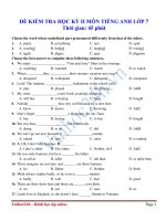
Anh văn Chuyên ngành Nhiệt
English for thermal engineering
LOGO
1
Chapter 4 Refrigeration and heat pump cycles
Contents
1
The fundamentals of refrigeration
2
Air conditioning systems
3
Ventilating system
2
Tài liệu tham khảo
1. Fundamentals of thermal-fluid science, Y. A. Çengel.
2. Fundamentals of thermodynamics (sixth edition),
Sonntag, Borgnakke and van Wylen.
3. Fundamentals of engineering thermodynamics (Fifth
edition), Michael J. Moran, Howard N. Shapiro.
3
4.1 The fundamentals of refrigeration cycle
The reversed Carnot cycle (refrigerator and heat pump)
The refrigerant absorbs heat
isothermally from a low-temperature
source at TL. in the amount of QL
(process 1-2), is compressed
isentropically to state 3 (temperature
rises to TH), rejects heat isothermally
to a high-temperature sink at TH in
the amount of QH (process 3-4), and
expands isentropically to state 1
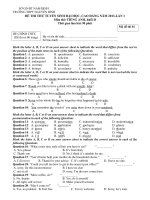
Schematic of a Carnot refrigerator and T-s diagram of
the reversed Carnot cycle
(temperature drops to TL). The
refrigerant changes from a saturated
vapor state to a saturated liquid state
in the condenser during process 3-4.
4
4.1 The fundamentals of refrigeration
The reversed Carnot cycle (refrigerator and heat pump)
The coefficients of performance of
Carnot refrigerators and heat pumps
are expressed in terms of temperatures
as:
and
Schematic of a Carnot refrigerator and T-s
diagram of the reversed Carnot cycle
5
4.1 The fundamentals of refrigeration
The reversed Carnot cycle (refrigerator and heat pump)
Notes:
-Both COPs increase as the difference between the two temperatures
decreases, that is, as TL rises or TH falls;
-The reversed Carnot cycle is the most efficient refrigeration cycle operating
between two specific temperature levels.
-Processes 2-3 and 4-1 cannot be approximated closely in practice since:
+ Process 2-3 involves the compression of a liquid–vapor mixture
a
compressor that will handle two phases;
+ Process 4-1 involves the expansion of high-moisture-content refrigerant.
6
4.1 The fundamentals of refrigeration
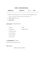
The ideal vapor-compression refrigeration cycle
Schematic and T-s diagram for the ideal vaporcompression refrigeration cycle
7
4.1 The fundamentals of refrigeration
The ideal vapor-compression refrigeration cycle
State 1 - Saturated vapor
State 2 - Superheated vapor
State 3 - Saturated liquid
State 4 - Low-quality saturated mixture
This cycle consists of 4 processes as follow:
1-2 Isentropic compression in a compressor
2-3 Constant-pressure heat rejection in a condenser
3-4 Throttling in an expansion device
4-1 Constant-pressure heat absorption in an evaporator
An ordinary household refrigerator
8
4.1 The fundamentals of refrigeration
The ideal vapor-compression refrigeration cycle
All four components associated with the vaporcompression refrigeration cycle are steady-flow
devices, and thus all four processes that make
up the cycle can be analyzed as steady-flow
processes.
The steady-flow energy equation on a unit-mass
basis reduces to:
The P-h diagram of an ideal vaporcompression refrigeration cycle
The COPs of refrigerators and heat pumps operating on the vapor-compression
refrigeration cycle can be expressed as
or
9
4.1 The fundamentals of refrigeration
The ideal vapor-compression refrigeration cycle
Example:
A refrigerator uses refrigerant-134a as the working fluid and operates on an
ideal vapor-compression refrigeration cycle between 0.14 and 0.8 MPa. If the
mass flow rate of the refrigerant is 0.05 kg/s, determine (a) the rate of heat
removal from the refrigerated space and the power input to the compressor, (b)
the rate of heat rejection to the environment, and (c) the COP of the refrigerator
Solution:
From the refrigerant-134a tables, the enthalpies of the refrigerant at
all four states are determined as follows:
10
4.1 The fundamentals of refrigeration
The ideal vapor-compression refrigeration cycle
Example:
A refrigerator uses refrigerant-134a as the working fluid and operates on an
ideal vapor-compression refrigeration cycle between 0.14 and 0.8 MPa. If the
mass flow rate of the refrigerant is 0.05 kg/s, determine (a) the rate of heat
removal from the refrigerated space and the power input to the compressor, (b)
the rate of heat rejection to the environment, and (c) the COP of the refrigerator
Solution:
From the refrigerant-134a tables, the enthalpies of the refrigerant at
all four states are determined as follows:
11
4.1 The fundamentals of refrigeration
The ideal vapor-compression refrigeration cycle
Solution:
a. The rate of heat removal from the refrigerated space and the power input to the
compressor
and
b. The rate of heat rejection from the refrigerant to the environment is
c. The coefficient of performance of the refrigerator is
12
4.1 The fundamentals of refrigeration
The actual vapor-compression refrigeration cycle
Schematic and T-s diagram for the actual vapor-compression refrigeration cycle. 13
4.1 The fundamentals of refrigeration
The actual vapor-compression refrigeration cycle
14
4.1 The fundamentals of refrigeration
The actual vapor-compression refrigeration cycle
15
4.2 Air conditioning system
Method of cooling air
1. Spray type washer
2. Surface type cooler:
Indirect: By heat exchange with water which has
been cooled by a refrigerant.
Direct: By heat exchange in evaporator of a
refrigerator system
16
4.2 Air conditioning system
Types of system
1. Cooling only
2. Cooling or heating
3. Cooling and heating with control of humidity
(full air conditioning)
17
4.2 Air conditioning system
A. Spray type washer
Air washer are sheet metal, or sometimes bricks or
concrete chambers, in which air is drawn through a mist
caused by spray nozzles and then through eliminator to
remove particles of water not evaporated into the air.
The water for the spray nozzles is recirculated by a pump
and can be heated or cooled. A tempering heater is
installed before, and a reheating battery after the air
washer
A typical air washer
18
4.2 Air conditioning system
B. Surface type coolers
B1. Self-contained wall or window unit
Unit mounted in wall or window, evaporator inside
the room and condenser outside room
Advantages: Low cost, flexible and simple.
Disadvantages: Short life; noise; poor control; poor
filtration and air distribution; lack of fresh air supply…
Applications: Small building; individual rooms
19
4.2 Air conditioning system
B. Surface type coolers
B2. Split direct expansion unit
Air cooled condenser is separate and remote from indoor
unit. Compressor is in the outdoor unit
Advantages: Indoor unit can be ceiling mounted; silencers
can be incorporated for indoor unit; Multiple refrigerant
circuits give improved control; Relative simple
Disadvantages: Restriction on length of refrigerant piping
and the difference in level between indoor and outdoor
units; Limited fresh air supply.
Applications: Small shops; computer rooms, individual
rooms or areas.
20
4.2 Air conditioning system
B. Surface type coolers
B2. Split direct expansion unit
21
4.2 Air conditioning system
B. Surface type coolers
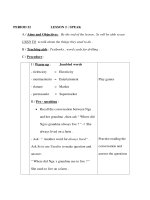
B3. Packaged air conditioning unit
Package units house all the components of an air
conditioning system in one unit (the compressor and
condenser coil, evaporator coil, fans)
Types: Air cooled condenser and water cooled condenser
Capacities: Fixed rate capacities of 3, 5, 7, 10 and 15 tons
Advantages: easy to control and install; initial costs is
lower than of the central systems…
Disadvantages: less flexible of air flow rates, condenser
and evaporator sizes; noise; difficult to control exact
humidity; short life;…
22
4.2 Air conditioning system
B. Surface type coolers
B3. Packaged air conditioning unit
Air cooled
condenser,
install in roof of
buildings
23
4.2 Air conditioning system
B. Surface type coolers
B3. Packaged air conditioning unit
Water cooled condenser, install in roof of buildings
24
4.2 Air conditioning system
B. Surface type coolers
B4. Variable Refrigerant Volume (VRV) or Variable
Refrigerant Flow (VRF)
* VRVs/VRFs utilize a larger external condenser to provide
cooling or heating to many indoor Fan Coil Units (FCU).
The system varies the quantity of refrigerant flowing based on
the demand for cooling or heating.
* The units are able to provide simultaneous heating or
cooling to different indoor units.
* Very efficient system.
Applications: Buildings, supermarkets…
25