DSIGN OF REINFORCED CONCRETE BROWN
Bạn đang xem bản rút gọn của tài liệu. Xem và tải ngay bản đầy đủ của tài liệu tại đây (13.88 MB, 742 trang )
Design of
Reinforced Concrete
Design of
Reinforced Concrete
ACI 318-11 Code Edition
Jack C. McCormac
Clemson University
Russell H. Brown
Clemson University
NINTH
EDITION
VP & EXECUTIVE PUBLISHER
MARKETING MANAGER
ACQUISITIONS EDITOR
SENIOR PRODUCTION EDITOR
CREATIVE DIRECTOR
SENIOR DESIGNER
PHOTO EDITOR
COVER PHOTO
Don Fowley
Christopher Ruel
Jennifer Welter
Sujin Hong
Harry Nolan
Thomas Nery
Sheena Goldstein
Frank Leung/iStockphoto
This book was set in 10/12 Times by Laserwords Private Limited and printed and bound by Courier. The cover was printed by Courier.
This book is printed on acid free paper. ∞
Founded in 1807, John Wiley & Sons, Inc. has been a valued source of knowledge and understanding for more than 200 years, helping people
around the world meet their needs and fulfill their aspirations. Our company is built on a foundation of principles that include responsibility to the
communities we serve and where we live and work. In 2008, we launched a Corporate Citizenship Initiative, a global effort to address the
environmental, social, economic, and ethical challenges we face in our business. Among the issues we are addressing are carbon impact, paper
specifications and procurement, ethical conduct within our business and among our vendors, and community and charitable support. For more
information, please visit our website: www.wiley.com/go/citizenship.
Copyright © 2014, 2009, 2006, 2005 John Wiley & Sons, Inc. All rights reserved.
No part of this publication may be reproduced, stored in a retrieval system or transmitted in any form or by any means, electronic, mechanical,
photocopying, recording, scanning or otherwise, except as permitted under Sections 107 or 108 of the 1976 United States Copyright Act, without
either the prior written permission of the Publisher or authorization through payment of the appropriate per-copy fee to the Copyright Clearance
Center, Inc., 222 Rosewood Drive, Danvers, MA 01923, website www.copyright.com. Requests to the Publisher for permission should be addressed
to the Permissions Department, John Wiley & Sons, Inc., 111 River Street, Hoboken, NJ 07030-5774, (201) 748-6011, fax (201) 748-6008, website
www.wiley.com/go/permissions.
Evaluation copies are provided to qualified academics and professionals for review purposes only, for use in their courses during the next academic
year. These copies are licensed and may not be sold or transferred to a third party. Upon completion of the review period, please return the
evaluation copy to Wiley. Return instructions and a free of charge return mailing label are available at www.wiley.com/go/returnlabel. If you have
chosen to adopt this textbook for use in your course, please accept this book as your complimentary desk copy. Outside of the United States, please
contact your local sales representative.
ISBN: 978-1-118-12984-5
ISBN: 978-1-118-43081-1 (BRV)
Printed in the United States of America
10 9 8 7 6 5 4 3 2 1
Brief Contents
Preface
1 Introduction
2 Flexural Analysis of Beams
3 Strength Analysis of Beams According to ACI Code
4 Design of Rectangular Beams and One-Way Slabs
5 Analysis and Design of T Beams and Doubly Reinforced Beams
6 Serviceability
7 Bond, Development Lengths, and Splices
8 Shear and Diagonal Tension
9 Introduction to Columns
10 Design of Short Columns Subject to Axial Load and Bending
11 Slender Columns
12 Footings
13 Retaining Walls
14 Continuous Reinforced Concrete Structures
15 Torsion
16 Two-Way Slabs, Direct Design Method
17 Two-Way Slabs, Equivalent Frame Method
18 Walls
19 Prestressed Concrete
20 Reinforced Concrete Masonry
A Tables and Graphs: U.S. Customary Units
B Tables in SI Units
C The Strut-and-Tie Method of Design
D Seismic Design of Reinforced Concrete Structures
Glossary
Index
xv
1
35
65
82
112
154
184
223
263
281
317
347
394
431
470
492
532
547
567
602
631
669
675
683
699
703
v
Contents
Preface
1 Introduction
xv
1
1.1
Concrete and Reinforced Concrete, 1
1.2
Advantages of Reinforced Concrete as a Structural Material, 1
1.3
Disadvantages of Reinforced Concrete as a Structural Material, 2
1.4
Historical Background, 3
1.5
Comparison of Reinforced Concrete and Structural Steel for Buildings and Bridges, 5
1.6
Compatibility of Concrete and Steel, 6
1.7
Design Codes, 6
1.8
SI Units and Shaded Areas, 7
1.9
Types of Portland Cement, 7
1.10 Admixtures, 9
1.11 Properties of Concrete, 10
1.12 Aggregates, 18
1.13 High-Strength Concretes, 19
1.14 Fiber-Reinforced Concretes, 20
1.15 Concrete Durability, 21
1.16 Reinforcing Steel, 22
1.17 Grades of Reinforcing Steel, 24
1.18 SI Bar Sizes and Material Strengths, 25
1.19 Corrosive Environments, 26
1.20 Identifying Marks on Reinforcing Bars, 26
1.21 Introduction to Loads, 28
1.22 Dead Loads, 28
1.23 Live Loads, 29
1.24 Environmental Loads, 30
1.25 Selection of Design Loads, 32
1.26 Calculation Accuracy, 33
1.27 Impact of Computers on Reinforced Concrete Design, 34
Problems, 34
2 Flexural Analysis of Beams
35
2.1
Introduction, 35
2.2
Cracking Moment, 38
2.3
Elastic Stresses—Concrete Cracked, 41
2.4
Ultimate or Nominal Flexural Moments, 48
2.5
SI Example, 51
2.6
Computer Examples, 52
Problems, 54
vii
viii
CONTENTS
3 Strength Analysis of Beams According to ACI Code
65
3.1
Design Methods, 65
3.2
Advantages of Strength Design, 66
3.3
Structural Safety, 66
3.4
Derivation of Beam Expressions, 67
3.5
Strains in Flexural Members, 70
3.6
Balanced Sections, Tension-Controlled Sections, and Compression-Controlled or Brittle Sections, 71
3.7
Strength Reduction or φ Factors, 71
3.8
Minimum Percentage of Steel, 74
3.9
Balanced Steel Percentage, 75
3.10 Example Problems, 76
3.11 Computer Examples, 79
Problems, 80
4 Design of Rectangular Beams and One-Way Slabs
82
4.1
Load Factors, 82
4.2
Design of Rectangular Beams, 85
4.3
Beam Design Examples, 89
4.4
Miscellaneous Beam Considerations, 95
4.5
Determining Steel Area When Beam Dimensions Are Predetermined, 96
4.6
Bundled Bars, 98
4.7
One-Way Slabs, 99
4.8
Cantilever Beams and Continuous Beams, 102
4.9
SI Example, 103
4.10 Computer Example, 105
Problems, 106
5 Analysis and Design of T Beams and Doubly Reinforced Beams
112
5.1
T Beams, 112
5.2
Analysis of T Beams, 114
5.3
Another Method for Analyzing T Beams, 118
5.4
Design of T Beams, 120
5.5
Design of T Beams for Negative Moments, 125
5.6
L-Shaped Beams, 127
5.7
Compression Steel, 127
5.8
Design of Doubly Reinforced Beams, 132
5.9
SI Examples, 136
5.10 Computer Examples, 138
Problems, 143
6 Serviceability
6.1
6.2
6.3
Introduction, 154
Importance of Deflections, 154
Control of Deflections, 155
154
CONTENTS
ix
6.4
Calculation of Deflections, 157
6.5
Effective Moments of Inertia, 158
6.6
Long-Term Deflections, 160
6.7
Simple-Beam Deflections, 162
6.8
Continuous-Beam Deflections, 164
6.9
Types of Cracks, 170
6.10 Control of Flexural Cracks, 171
6.11 ACI Code Provisions Concerning Cracks, 175
6.12 Miscellaneous Cracks, 176
6.13 SI Example, 176
6.14 Computer Example, 177
Problems, 179
7 Bond, Development Lengths, and Splices
184
7.1
Cutting Off or Bending Bars, 184
7.2
Bond Stresses, 187
7.3
Development Lengths for Tension Reinforcing, 189
7.4
Development Lengths for Bundled Bars, 197
7.5
Hooks, 199
7.6
Development Lengths for Welded Wire Fabric in Tension, 203
7.7
Development Lengths for Compression Bars, 204
7.8
Critical Sections for Development Length, 206
7.9
Effect of Combined Shear and Moment on Development Lengths, 206
7.10 Effect of Shape of Moment Diagram on Development Lengths, 207
7.11 Cutting Off or Bending Bars (Continued), 208
7.12 Bar Splices in Flexural Members, 211
7.13 Tension Splices, 213
7.14 Compression Splices, 213
7.15 Headed and Mechanically Anchored Bars, 214
7.16 SI Example, 215
7.17 Computer Example, 216
Problems, 217
8 Shear and Diagonal Tension
8.1
8.2
8.3
8.4
8.5
8.6
8.7
8.8
8.9
8.10
8.11
8.12
8.13
Introduction, 223
Shear Stresses in Concrete Beams, 223
Lightweight Concrete, 224
Shear Strength of Concrete, 225
Shear Cracking of Reinforced Concrete Beams, 226
Web Reinforcement, 227
Behavior of Beams with Web Reinforcement, 229
Design for Shear, 231
ACI Code Requirements, 232
Shear Design Example Problems, 237
Economical Spacing of Stirrups, 247
Shear Friction and Corbels, 249
Shear Strength of Members Subjected to Axial Forces, 251
223
x CONTENTS
8.14 Shear Design Provisions for Deep Beams, 253
8.15 Introductory Comments on Torsion, 254
8.16 SI Example, 256
8.17 Computer Example, 257
Problems, 258
9 Introduction to Columns
263
9.1
General, 263
9.2
Types of Columns, 264
9.3
Axial Load Capacity of Columns, 266
9.4
Failure of Tied and Spiral Columns, 266
9.5
Code Requirements for Cast-in-Place Columns, 269
9.6
Safety Provisions for Columns, 271
9.7
Design Formulas, 272
9.8
Comments on Economical Column Design, 273
9.9
Design of Axially Loaded Columns, 274
9.10 SI Example, 277
9.11 Computer Example, 278
Problems, 279
10 Design of Short Columns Subject to Axial Load and Bending
281
10.1 Axial Load and Bending, 281
10.2 The Plastic Centroid, 282
10.3 Development of Interaction Diagrams, 284
10.4 Use of Interaction Diagrams, 290
10.5 Code Modifications of Column Interaction Diagrams, 292
10.6 Design and Analysis of Eccentrically Loaded Columns Using Interaction Diagrams, 294
10.7 Shear in Columns, 301
10.8 Biaxial Bending, 302
10.9 Design of Biaxially Loaded Columns, 306
10.10 Continued Discussion of Capacity Reduction Factors, φ, 309
10.11 Computer Example, 311
Problems, 312
11 Slender Columns
11.1
11.2
11.3
11.4
11.5
11.6
11.7
11.8
11.9
11.10
Introduction, 317
Nonsway and Sway Frames, 317
Slenderness Effects, 318
Determining k Factors with Alignment Charts, 321
Determining k Factors with Equations, 322
First-Order Analyses Using Special Member Properties, 323
Slender Columns in Nonsway and Sway Frames, 324
ACI Code Treatments of Slenderness Effects, 328
Magnification of Column Moments in Nonsway Frames, 328
Magnification of Column Moments in Sway Frames, 333
317
CONTENTS
xi
11.11 Analysis of Sway Frames, 336
11.12 Computer Examples, 342
Problems, 344
12 Footings
347
12.1 Introduction, 347
12.2 Types of Footings, 347
12.3 Actual Soil Pressures, 350
12.4 Allowable Soil Pressures, 351
12.5 Design of Wall Footings, 352
12.6 Design of Square Isolated Footings, 357
12.7 Footings Supporting Round or Regular Polygon-Shaped Columns, 364
12.8 Load Transfer from Columns to Footings, 364
12.9 Rectangular Isolated Footings, 369
12.10 Combined Footings, 372
12.11 Footing Design for Equal Settlements, 378
12.12 Footings Subjected to Axial Loads and Moments, 380
12.13 Transfer of Horizontal Forces, 382
12.14 Plain Concrete Footings, 383
12.15 SI Example, 386
12.16 Computer Examples, 388
Problems, 391
13 Retaining Walls
394
13.1 Introduction, 394
13.2 Types of Retaining Walls, 394
13.3 Drainage, 397
13.4 Failures of Retaining Walls, 398
13.5 Lateral Pressure on Retaining Walls, 399
13.6 Footing Soil Pressures, 404
13.7 Design of Semigravity Retaining Walls, 405
13.8 Effect of Surcharge, 408
13.9 Estimating the Sizes of Cantilever Retaining Walls, 409
13.10 Design Procedure for Cantilever Retaining Walls, 413
13.11 Cracks and Wall Joints, 424
Problems, 426
14 Continuous Reinforced Concrete Structures
14.1
14.2
14.3
14.4
14.5
14.6
14.7
Introduction, 431
General Discussion of Analysis Methods, 431
Qualitative Influence Lines, 431
Limit Design, 434
Limit Design under the ACI Code, 442
Preliminary Design of Members, 445
Approximate Analysis of Continuous Frames for Vertical Loads, 445
431
xii
CONTENTS
14.8 Approximate Analysis of Continuous Frames for Lateral Loads, 454
14.9 Computer Analysis of Building Frames, 458
14.10 Lateral Bracing for Buildings, 459
14.11 Development Length Requirements for Continuous Members, 459
Problems, 465
15 Torsion
470
15.1 Introduction, 470
15.2 Torsional Reinforcing, 471
15.3 Torsional Moments that Have to Be Considered in Design, 474
15.4 Torsional Stresses, 475
15.5 When Torsional Reinforcing Is Required by the ACI, 476
15.6 Torsional Moment Strength, 477
15.7 Design of Torsional Reinforcing, 478
15.8 Additional ACI Requirements, 479
15.9 Example Problems Using U.S. Customary Units, 480
15.10 SI Equations and Example Problem, 483
15.11 Computer Example, 487
Problems, 488
16 Two-Way Slabs, Direct Design Method
492
16.1 Introduction, 492
16.2 Analysis of Two-Way Slabs, 495
16.3 Design of Two-Way Slabs by the ACI Code, 495
16.4 Column and Middle Strips, 496
16.5 Shear Resistance of Slabs, 497
16.6 Depth Limitations and Stiffness Requirements, 500
16.7 Limitations of Direct Design Method, 505
16.8 Distribution of Moments in Slabs, 506
16.9 Design of an Interior Flat Plate, 511
16.10 Placing of Live Loads, 514
16.11 Analysis of Two-Way Slabs with Beams, 517
16.12 Transfer of Moments and Shears between Slabs and Columns, 522
16.13 Openings in Slab Systems, 528
16.14 Computer Example, 528
Problems, 530
17 Two-Way Slabs, Equivalent Frame Method
17.1 Moment Distribution for Nonprismatic Members, 532
17.2 Introduction to the Equivalent Frame Method, 533
17.3 Properties of Slab Beams, 535
17.4 Properties of Columns, 538
17.5 Example Problem, 540
17.6 Computer Analysis, 544
17.7 Computer Example, 545
Problems, 546
532
CONTENTS
18 Walls
xiii
547
18.1 Introduction, 547
18.2 Non–Load-Bearing Walls, 547
18.3 Load-Bearing Concrete Walls—Empirical Design Method, 549
18.4 Load-Bearing Concrete Walls—Rational Design, 552
18.5 Shear Walls, 554
18.6 ACI Provisions for Shear Walls, 558
18.7 Economy in Wall Construction, 563
18.8 Computer Example, 564
Problems, 565
19 Prestressed Concrete
567
19.1 Introduction, 567
19.2 Advantages and Disadvantages of Prestressed Concrete, 569
19.3 Pretensioning and Posttensioning, 569
19.4 Materials Used for Prestressed Concrete, 570
19.5 Stress Calculations, 572
19.6 Shapes of Prestressed Sections, 576
19.7 Prestress Losses, 579
19.8 Ultimate Strength of Prestressed Sections, 582
19.9 Deflections, 586
19.10 Shear in Prestressed Sections, 590
19.11 Design of Shear Reinforcement, 591
19.12 Additional Topics, 595
19.13 Computer Example, 597
Problems, 598
20 Reinforced Concrete Masonry
602
20.1 Introduction, 602
20.2 Masonry Materials, 602
20.3 Specified Compressive Strength of Masonry, 606
20.4 Maximum Flexural Tensile Reinforcement, 607
20.5 Walls with Out-of-Plane Loads—Non–Load-Bearing Walls, 607
20.6 Masonry Lintels, 611
20.7 Walls with Out-of-Plane Loads—Load-Bearing, 616
20.8 Walls with In-Plane Loading—Shear Walls, 623
20.9 Computer Example, 628
Problems, 630
A Tables and Graphs: U.S. Customary Units
631
B Tables in SI Units
669
xiv CONTENTS
C The Strut-and-Tie Method of Design
C.1
C.2
C.3
C.4
C.5
C.6
C.7
C.8
C.9
675
Introduction, 675
Deep Beams, 675
Shear Span and Behavior Regions, 675
Truss Analogy, 677
Definitions, 678
ACI Code Requirements for Strut-and-Tie Design, 678
Selecting a Truss Model, 679
Angles of Struts in Truss Models, 681
Design Procedure, 682
D Seismic Design of Reinforced Concrete Structures
683
D.1 Introduction, 683
D.2 Maximum Considered Earthquake, 684
D.3 Soil Site Class, 684
D.4 Risk and Importance Factors, 686
D.5 Seismic Design Categories, 687
D.6 Seismic Design Loads, 687
D.7 Detailing Requirements for Different Classes of Reinforced Concrete Moment Frames, 691
Problems, 698
Glossary
699
Index
703
McCormac fpref.tex
V2 - January 10, 2013 6:36 P.M.
Preface
Audience
This textbook presents an introduction to reinforced concrete design. We authors hope the
material is written in such a manner as to interest students in the subject and to encourage
them to continue its study in the years to come. The text was prepared with an introductory
three-credit course in mind, but sufficient material is included for an additional three-credit
course.
New to This Edition
Updated Code
With the ninth edition of this text, the contents have been updated to conform to the 2011
Building Code of the American Concrete Institute (ACI 318-11). Changes to this edition of the
code include:
• Factored load combinations are now based on ASCE/SEI 7-10, which now treats wind
as a strength level load.
• Minor revisions to development length to headed bars.
• Addition of minimum reinforcement provisions to deep beams.
• Introduction of Grade 80 deformed bars in accordance with ASTM 615 and ASTM 706.
• Zinc and epoxy dual-coated reinforcing bars are now permitted in accordance with ASTM
A1055.
New Chapter on Concrete Masonry
A new chapter on strength design of reinforced concrete masonry has been added to replace the
previous Chapter 20 on formwork. Surveys revealed that the forms chapter was not being used
and that a chapter on masonry would be more valuable. Because strength design of reinforced
concrete masonry is so similar to that of reinforced concrete, the authors felt that this would be
a logical extension to the application of the theories developed earlier in the text. The design
of masonry lintels, walls loaded out-of-plane, and shear walls are included. The subject of this
chapter could easily occupy an entire textbook, so this chapter is limited in scope to only the
basics. An example of the design of each type of masonry element is also included to show
the student some typical applications.
xv
Page xv
McCormac fpref.tex
xvi
V2 - January 10, 2013 6:36 P.M.
PREFACE
Units Added to Example Problems
The example problems now have units associated with the input values. This will assist the
student in determining the source of each input value as well as help in the use of dimensional
analysis in determining the correct answers and the units of the answers. Often the student
can catch errors in calculations simply by checking the dimensions of the calculated answer
against what the units are known to be.
Organization
The text is written in the order that the authors feel would follow the normal sequence of
presentation for an introductory course in reinforced concrete design. In this way, it is hoped
that skipping back and forth from chapter to chapter will be minimized. The material on
columns is included in three chapters (Chapters 9, 10, and 11). Some instructors do not have
time to cover the material on slender columns, so it was put in a separate chapter (Chapter
11). The remaining material on columns was separated into two chapters in order to emphasize
the difference between columns that are primarily axially loaded (Chapter 9) and those with
significant bending moment combined with axial load (Chapter 10). The material formerly in
Chapter 21, “Seismic Design of Concrete Structures,” has been updated and moved to a new
appendix (Appendix D).
Instructor and Student Resources
The website for the book is located at www.wiley.com/college/mccormac and contains the
following resources.
For Instructors
Solutions Manual A password-protected Solutions Manual, which contains complete solutions for all homework problems in the text, is available for download. Most are handwritten,
but some are carried out using spreadsheets or Mathcad.
Figures in PPT Format Also available are the figures from the text in PowerPoint format,
for easy creation of lecture slides.
Lecture Presentation Slides in PPT Format Presentation slides developed by Dr. Terry
Weigel of the University of Louisville are available for instructors who prefer to use PowerPoint
for their lectures. The PowerPoint files are posted rather than files in PDF format to permit the
instructor to modify them as appropriate for his or her class.
Sample Exams Examples of sample exams are included for most topics in the text. Problems in the back of each chapter are also suitable for exam questions.
Course Syllabus A course syllabus along with a typical daily schedule are included in
editable format.
Visit the Instructor Companion Site portion of the book website at www.wiley.com/
college/mccormac to register for a password. These resources are available for instructors
who have adopted the book for their course. The website may be updated periodically with
additional material.
Page xvi
McCormac fpref.tex V2 - January 10, 2013 6:36 P.M.
PREFACE
For Students and Instructors
Excel Spreadsheets Excel spreadsheets were created to provide the student and the instructor with tools to analyze and design reinforced concrete elements quickly to compare alternative
solutions. Spreadsheets are provided for most chapters of the text, and their use is selfexplanatory. Many of the cells contain comments to assist the new user. The spreadsheets
can be modified by the student or instructor to suit their more specific needs. In most cases,
calculations contained within the spreadsheets mirror those shown in the example problems
in the text. The many uses of these spreadsheets are illustrated throughout the text. At the
end of most chapters are example problems demonstrating the use of the spreadsheet for that
particular chapter. Space does not permit examples for all of the spreadsheet capabilities. The
examples chosen were thought by the authors to be the most relevant.
Visit the Student Companion Site portion of the book website at www.wiley.com/
college/mccormac to download this software.
Acknowledgments
We wish to thank the following people who reviewed this edition:
Madasamy Arockiasamy, Florida Atlantic University
Pinaki R. Chakrabarti, California State University, Fullerton
Wonchang Choi, North Carolina A&T State University
Apostolos Fafitis, Arizona State University
Farhad Reza, Minnesota State University
Rudolf Seracino, North Carolina State University
Brian Swartz, University of Hartford
Xi Xu, Stevens Institute of Technology
Finally, we are also grateful to the reviewers and users of the previous editions of this
book for their suggestions, corrections, and criticisms. We are always grateful to anyone who
takes the time to contact us concerning any part of the book.
Jack C. McCormac
Russell H. Brown
xvii
Page xvii
McCormac fpref.tex V2 - January 10, 2013 6:36 P.M. Page xviii
McCormac c01.tex V2 - January 9, 2013 2:57 P.M.
Introduction
1.1
C H A PT E R 1
Concrete and Reinforced Concrete
Concrete is a mixture of sand, gravel, crushed rock, or other aggregates held together in a
rocklike mass with a paste of cement and water. Sometimes one or more admixtures are added
to change certain characteristics of the concrete such as its workability, durability, and time of
hardening.
As with most rocklike substances, concrete has a high compressive strength and a very
low tensile strength. Reinforced concrete is a combination of concrete and steel wherein the
steel reinforcement provides the tensile strength lacking in the concrete. Steel reinforcing is also
capable of resisting compression forces and is used in columns as well as in other situations,
which are described later.
1.2
Advantages of Reinforced Concrete as a
Structural Material
Reinforced concrete may be the most important material available for construction. It is used
in one form or another for almost all structures, great or small—buildings, bridges, pavements,
dams, retaining walls, tunnels, drainage and irrigation facilities, tanks, and so on.
The tremendous success of this universal construction material can be understood quite
easily if its numerous advantages are considered. These include the following:
1. It has considerable compressive strength per unit cost compared with most other materials.
2. Reinforced concrete has great resistance to the actions of fire and water and, in fact, is
the best structural material available for situations where water is present. During fires
of average intensity, members with a satisfactory cover of concrete over the reinforcing
bars suffer only surface damage without failure.
3. Reinforced concrete structures are very rigid.
4. It is a low-maintenance material.
5. As compared with other materials, it has a very long service life. Under proper conditions,
reinforced concrete structures can be used indefinitely without reduction of their loadcarrying abilities. This can be explained by the fact that the strength of concrete does
not decrease with time but actually increases over a very long period, measured in years,
because of the lengthy process of the solidification of the cement paste.
6. It is usually the only economical material available for footings, floor slabs, basement
walls, piers, and similar applications.
7. A special feature of concrete is its ability to be cast into an extraordinary variety of
shapes from simple slabs, beams, and columns to great arches and shells.
1
Page 1
McCormac c01.tex V2 - January 9, 2013 2:57 P.M.
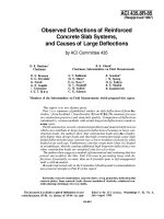
CHAPTER 1
Introduction
Courtesy of Portland Cement Association.
2
NCNB Tower in Charlotte, North Carolina, completed 1991.
8. In most areas, concrete takes advantage of inexpensive local materials (sand, gravel, and
water) and requires relatively small amounts of cement and reinforcing steel, which may
have to be shipped from other parts of the country.
9. A lower grade of skilled labor is required for erection as compared with other materials
such as structural steel.
1.3
Disadvantages of Reinforced Concrete as a
Structural Material
To use concrete successfully, the designer must be completely familiar with its weak points as
well as its strong ones. Among its disadvantages are the following:
1. Concrete has a very low tensile strength, requiring the use of tensile reinforcing.
2. Forms are required to hold the concrete in place until it hardens sufficiently. In addition, falsework or shoring may be necessary to keep the forms in place for roofs, walls,
floors, and similar structures until the concrete members gain sufficient strength to support themselves. Formwork is very expensive. In the United States, its costs run from
one-third to two-thirds of the total cost of a reinforced concrete structure, with average
Page 2
McCormac c01.tex V2 - January 10, 2013 9:10 P.M.
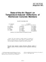
Courtesy of EFCO Corp.
1.4 Historical Background
The 320-ft-high Pyramid Sports Arena, Memphis, Tennessee.
values of about 50%. It should be obvious that when efforts are made to improve the
economy of reinforced concrete structures, the major emphasis is on reducing formwork
costs.
3. The low strength per unit of weight of concrete leads to heavy members. This becomes
an increasingly important matter for long-span structures, where concrete’s large dead
weight has a great effect on bending moments. Lightweight aggregates can be used to
reduce concrete weight, but the cost of the concrete is increased.
4. Similarly, the low strength per unit of volume of concrete means members will be
relatively large, an important consideration for tall buildings and long-span structures.
5. The properties of concrete vary widely because of variations in its proportioning and
mixing. Furthermore, the placing and curing of concrete is not as carefully controlled
as is the production of other materials, such as structural steel and laminated wood.
Two other characteristics that can cause problems are concrete’s shrinkage and creep.
These characteristics are discussed in Section 1.11 of this chapter.
1.4
Historical Background
Most people believe that concrete has been in common use for many centuries, but this is
not the case. The Romans did make use of a cement called pozzolana before the birth of
Christ. They found large deposits of a sandy volcanic ash near Mt. Vesuvius and in other
places in Italy. When they mixed this material with quicklime and water as well as sand
and gravel, it hardened into a rocklike substance and was used as a building material. One
might expect that a relatively poor grade of concrete would result, as compared with today’s
standards, but some Roman concrete structures are still in existence today. One example is
the Pantheon (a building dedicated to all gods), which is located in Rome and was completed
in a.d. 126.
The art of making pozzolanic concrete was lost during the Dark Ages and was not revived
until the eighteenth and nineteenth centuries. A deposit of natural cement rock was discovered
in England in 1796 and was sold as “Roman cement.” Various other deposits of natural cement
were discovered in both Europe and America and were used for several decades.
3
Page 3
McCormac c01.tex V2 - January 9, 2013 2:57 P.M.
4
CHAPTER 1
Introduction
The real breakthrough for concrete occurred in 1824, when an English bricklayer named
Joseph Aspdin, after long and laborious experiments, obtained a patent for a cement that he
called portland cement because its color was quite similar to that of the stone quarried on the
Isle of Portland off the English coast. He made his cement by taking certain quantities of clay
and limestone, pulverizing them, burning them in his kitchen stove, and grinding the resulting
clinker into a fine powder. During the early years after its development, his cement was used
primarily in stuccos.1 This wonderful product was adopted very slowly by the building industry
and was not even introduced in the United States until 1868; the first portland cement was not
manufactured in the United States until the 1870s.
The first uses of concrete are not very well known. Much of the early work was done
by the Frenchmen Franc¸ois Le Brun, Joseph Lambot, and Joseph Monier. In 1832, Le Brun
built a concrete house and followed it with the construction of a school and a church with
the same material. In about 1850, Lambot built a concrete boat reinforced with a network
of parallel wires or bars. Credit is usually given to Monier, however, for the invention of
reinforced concrete. In 1867, he received a patent for the construction of concrete basins or
tubs and reservoirs reinforced with a mesh of iron wire. His stated goal in working with this
material was to obtain lightness without sacrificing strength.2
From 1867 to 1881, Monier received patents for reinforced concrete railroad ties, floor
slabs, arches, footbridges, buildings, and other items in both France and Germany. Another
Frenchman, Franc¸ois Coignet, built simple reinforced concrete structures and developed basic
methods of design. In 1861, he published a book in which he presented quite a few applications.
He was the first person to realize that the addition of too much water to the mix greatly reduced
concrete’s strength. Other Europeans who were early experimenters with reinforced concrete
included the Englishmen William Fairbairn and William B. Wilkinson, the German G. A.
Wayss, and another Frenchman, Franc¸ois Hennebique.3,4
William E. Ward built the first reinforced concrete building in the United States in Port
Chester, New York, in 1875. In 1883, he presented a paper before the American Society of
Mechanical Engineers in which he claimed that he got the idea of reinforced concrete by
watching English laborers in 1867 trying to remove hardened cement from their iron tools.5
Thaddeus Hyatt, an American, was probably the first person to correctly analyze the
stresses in a reinforced concrete beam, and in 1877, he published a 28-page book on the
subject, entitled An Account of Some Experiments with Portland Cement Concrete, Combined
with Iron as a Building Material. In this book he praised the use of reinforced concrete and
said that “rolled beams (steel) have to be taken largely on faith.” Hyatt put a great deal of
emphasis on the high fire resistance of concrete.6
E. L. Ransome of San Francisco reportedly used reinforced concrete in the early 1870s
and was the originator of deformed (or twisted) bars, for which he received a patent in 1884.
These bars, which were square in cross section, were cold-twisted with one complete turn in
a length of not more than 12 times the bar diameter.7 (The purpose of the twisting was to
provide better bonding or adhesion of the concrete and the steel.) In 1890 in San Francisco,
Ransome built the Leland Stanford Jr. Museum. It is a reinforced concrete building 312 ft
long and 2 stories high in which discarded wire rope from a cable-car system was used as
tensile reinforcing. This building experienced little damage in the 1906 earthquake and the fire
1 Kirby,
R. S. and Laurson, P. G., 1932, The Early Years of Modern Civil Engineering (New Haven: Yale University Press),
p. 266.
2 Ibid., pp. 273–275.
3
Straub, H., 1964, A History of Civil Engineering (Cambridge: MIT Press), pp. 205–215. Translated from the German Die
Geschichte der Bauingenieurkunst (Basel: Verlag Birkhauser), 1949.
4 Kirby and Laurson, The Early Years of Modern Civil Engineering, pp. 273–275.
5 Ward, W. E., 1883, “B´
eton in Combination with Iron as a Building Material,” Transactions ASME, 4, pp. 388–403.
6 Kirby and Laurson, The Early Years of Modern Civil Engineering, p. 275.
7 American Society for Testing Materials, 1911, Proceedings, 11, pp. 66–68.
Page 4
McCormac c01.tex V2 - January 9, 2013 2:57 P.M.
Itar-Tass Photos/NewsCom.
1.5 Comparison of Reinforced Concrete and Structural Steel for Buildings and Bridges
Installation of the concrete gravity base substructure (CGBS) for the LUNA oil-and-gas
platform in the Sea of Okhotsk, Sakhalin region, Russia.
that ensued. The limited damage to this building and other concrete structures that withstood
the great 1906 fire led to the widespread acceptance of this form of construction on the West
Coast. Since the early 1900s, the development and use of reinforced concrete in the United
States has been very rapid.8,9
1.5
Comparison of Reinforced Concrete and Structural Steel
for Buildings and Bridges
When a particular type of structure is being considered, the student may be puzzled by the
question, “Should reinforced concrete or structural steel be used?” There is much joking on this
point, with the proponents of reinforced concrete referring to steel as that material that rusts
and those favoring structural steel referring to concrete as the material that, when overstressed,
tends to return to its natural state—that is, sand and gravel.
There is no simple answer to this question, inasmuch as both of these materials have
many excellent characteristics that can be utilized successfully for so many types of structures.
In fact, they are often used together in the same structures with wonderful results.
The selection of the structural material to be used for a particular building depends on
the height and span of the structure, the material market, foundation conditions, local building
codes, and architectural considerations. For buildings of less than 4 stories, reinforced concrete,
structural steel, and wall-bearing construction are competitive. From 4 to about 20 stories,
reinforced concrete and structural steel are economically competitive, with steel having been
used in most of the jobs above 20 stories in the past. Today, however, reinforced concrete
is becoming increasingly competitive above 20 stories, and there are a number of reinforced
concrete buildings of greater height around the world. The 74-story, 859-ft-high Water Tower
Place in Chicago is the tallest reinforced concrete building in the world. The 1465-ft CN tower
(not a building) in Toronto, Canada, is the tallest reinforced concrete structure in the world.
8
9
Wang, C. K. and Salmon, C. G., 1998, Reinforced Concrete Design, 6th ed. (New York: HarperCollins), pp. 3–5.
“The Story of Cement, Concrete and Reinforced Concrete,” Civil Engineering, November 1977, pp. 63–65.
5
Page 5