sdfafsadfsda38 sensor (1)
Bạn đang xem bản rút gọn của tài liệu. Xem và tải ngay bản đầy đủ của tài liệu tại đây (654.83 KB, 10 trang )
ISSN: 2319-8753
International Journal of Innovative Research in Science,
Engineering and Technology
(An ISO 3297: 2007 Certified Organization)
Vol. 3, Issue 12, December 2014
Sensor Network based Thermal Power Plant
Interlock Control and Remote Monitoring
System
Sriram kagitha1, T.S.S.Phani2, A.Pravin3
Pursuing M.Tech, Department of ECE, BVC Engg College, Vodalarevu, Andhra Pradesh, India1
Assistant Professor, M.Tech, Department of ECE, BVC Engg College, Vodalarevu, Andhra Pradesh, India2
Associate Professor, (Ph.D), HOD, Department of ECE, BVC Engg College, Vodalarevu, Andhra Pradesh, India3
ABSTRACT: Due to harmful working environment and remote location of Thermal power plant sites, it is dangerous
and time expensive to operate and maintenance. As the demand for power increases, increasing safety and reducing
operating and maintenance cost plays a vital role in increasing the reliability of the power plant. As the Thermal power
plant has to work for 24 hours and 365 days, it is not possible to monitor the parameters in site at each and every moment.
So remote monitoring is also needed. This project develops a sensor network based interlock control and remote
monitoring system. The system mainly consist Temperature sensor, Pressure sensor, Flow sensor, Level sensor, RPM
sensor, PH sensor, Vibration sensor, Voltage sensor. All the sensors data is processed using ARM processor. Using this
system we can control the operation of Thermal power plant in auto mode and monitor the parameters in work place. Also
we can communicate the sensor data to other PCs in remote locations using GSM technology.
KEYWORDS: ARM Processor, GSM module, Monitoring and Control, Thermal Power plant, Wireless Sensor
Networks (WSNs), ZIGBEE module.
I. INTRODUCTION
In Thermal power plant, Combustion of coal in the boiler converts the water into steam in boiler tubs. This steam
with high pressure and temperature flows into Turbine and rotates Turbine shaft. This Turbine shaft is connected to the
Generator shaft. By rotating Turbine Shaft Generator shaft also rotates and Power will be generated. Temperature,
Pressure and Flow are the three main parameters to be controlled in steam and water.
Boiler tubes will be puncture if temperature of steam increases. So, temperature of steam should be monitored
and controlled.
Increase in pressure and flow of steam increases the speed in rotation of turbine shaft which causes a great
damage to the Turbine and Generator. So, pressure and flow of the steam should be monitored and controlled. In Boiler
drum 50% of water and 50% of steam is present. Increase in % of steam in Boiler drum increases the pressure in it. If
Pressure in drum increases the drum may blast. So, level of steam should be monitored and controlled.
If RPM in Turbine increases the blades present in the turbine may damage. So, RPM of turbine shaft should be
controlled.
For pure water PH value is 7. If it is less than 7 the water is said to be acidic in nature. If it is greater than 7 the
water is said to be basic in nature. Acidic water corrodes the Boiler Tubes. Basic water forms coagulations when it is
heated. If coagulated steam fall on turbine blades causes damage to blades and produce vibrations in Turbine. So, PH
value should be measured and controlled.
Vibrations in Turbine and Voltage given to the auxiliary motors should be measured for operation and
maintenance purpose.
Copyright to IJIRSET
DOI: 10.15680/IJIRSET.2014.0312038
www.ijirset.com
18039
ISSN: 2319-8753
International Journal of Innovative Research in Science,
Engineering and Technology
(An ISO 3297: 2007 Certified Organization)
Vol. 3, Issue 12, December 2014
In this paper we mainly concentrate on how to control and monitor the temperature, pressure and flow of steam,
level in steam drum, RPM (Rotations Per Minute) of turbine shaft and PH (Presence of Hydrogen ions) of water in Boiler
drum. We also measure and monitor the vibrations generated in Turbine and voltage given to the motors. Wireless sensors
are mainly aimed to monitor and control various parameters in thermal power plant with relatively low power
consumption.
II. RELATED WORK
Previously in thermal power plants there is no advanced technology to operate in auto mode. The major
disadvantages of existing system are
There is no Interlock control.
There is no monitoring in remote place.
Aimed for oil processing [1] industries.
There is no auto control of PH value in steam and less number of sensors is used.
Takes more time to process sensor data.
Number of parameters monitored and controlled is less.
The power plant operating system in this paper adopted wireless communication technology and embedded
systems. This paper mainly discusses the hardware and software of embedded components used in the system. It
improves the safety and reliability of the system. This paper overcomes the disadvantages of existing system and
improves the efficiency of thermal power plant. The major advantages of this project is
Interlock control of different parameters of steam.
Monitoring in remote and workplace.
Controls PH value of steam.
Processing speed is fast compared to the existing system.
All the parameters in the plant are considered and increases the safety and reduces the man power.
The monitoring and controlling section of this system mainly consists of LPC3130 microcontroller with
ARM9 processor, the sensor data is communicated in work space via ZIGBEE in workplace and via GSM Technology
to remote place.
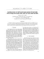
III. SYSTEM STRUCTURE
The system structure mainly consists of Transmitter Section, Receiver Section 1 and Receiver Section 2 which
are shown in figure 1, figure 2 and figure 3 respectively.
Transmitter section mainly consists of eight sensor networks in this system which senses various parameters in
Thermal Power plant. Various sensors used here are Temperature, Pressure, Level, Flow, RPM, PH, Voltage and
Vibration Sensors. As the output through these sensors is a physical quantity, they are connected to ADC (Analog to
Digital Converter) to convert this analog information to digital format and then this digital information is processed
using LPC3130.
The controlling section [2] of this system is of great interest. The entire sensor’s data are stored in the
processor memory and continuously monitored. If any of the sensors data exceeds or below its threshold level, it
indicates the workers through a display device like PC in work place and through a GSM receiver in remote place
which have connections to the microcontroller. Also we can automatically control the environment of Thermal Power
plant if any sensor level is high or low. Here four external devices are connected to the system. They are Attemperator,
Coal Feeder, Atmospheric vent and HP dosing pump.
Copyright to IJIRSET
DOI: 10.15680/IJIRSET.2014.0312038
www.ijirset.com
18040
ISSN: 2319-8753
International Journal of Innovative Research in Science,
Engineering and Technology
(An ISO 3297: 2007 Certified Organization)
Vol. 3, Issue 12, December 2014
TEMPERATURE
SENSOR
VOLTAGE
SENSOR
ZIGBEE
TRANSMITTER
GSM
TRANSMITTER
PRESSURE
SENSOR
LEVEL SENSOR
ATTEMPERATOR
COAL
FEEDER
LPC 2148
ADC
ACTUATOR CONTROL
FLOW SENSOR
ATMOSPHERIC
VENT
HP DOSING
PUMP
RPM SENSOR
PH SENSOR
VIBRATION
SENSOR
Fig 1: Block diagram: Transmitter Section
ZIGBEE
RECEIVER
UART
PC
Fig 2: Block Diagram: Receiver Section 1
GSM
RECEIVER
Fig 3: Block Diagram: Receiver Section 2
Not only the sensor’s level is indicated to the workers at working environment through PC’s using Zigbee
module and also transmits this data to GSM receiver present in the remote place. Zigbee transmitter and GSM
transmitters are to LPC3130 controller. It continuously checks out the sensor data and sends to the Zigbee and GSM
receiver.
1. Function of LPC2148
LPC is a family of microcontroller ICs by NXP semiconductors (formerly Philip semiconductors).The LPC
chips are based on the 32-bit RISC ARM cores from ARM Holdings, such as Cortex-M4F, Cortex-M3, Cortex-M0+,
Cortex-M0, ARM9 and ARM7 cores.
Copyright to IJIRSET
DOI: 10.15680/IJIRSET.2014.0312038
www.ijirset.com
18041
ISSN: 2319-8753
International Journal of Innovative Research in Science,
Engineering and Technology
(An ISO 3297: 2007 Certified Organization)
Vol. 3, Issue 12, December 2014
The LPC 2141/2/4/6/8 microcontrollers are based on a 32/16 bit ARM7TDMI-S processor with real time
emulation and embedded trace support with an embedded high speed flash memory ranging from 32KB to 512 KB. It is
a general purpose 32-bit microprocessor that offers high performance and very low power consumption and its
architecture is based on RISC principles.
The main features of LPC2148 include
8 to 40 KB on-chip static RAM.
128 bit wide interface /accelerator enable high speed 60 MHz operation.
In-System/In-Application Programming (ISP/IAP) via on-chip boot-loader software.
USB 2.0 full speed compliant device controller with 2 KB of end point RAM.
One or two 10-bit A/D converters provide a total of 6/14 analog inputs.
Single 10-bit D/A converter provide variable analog output.
Two 32-bit timers/external event counters, PWM unit and watchdog.
Multiple serial interfaces including two UARTs, two fast 12C-bus, SPI and SSPwith buffering and variable
data length capabilities.
2. Function of zigbee
Zigbee is a specification for a suite of high level communication protocols used to create personal area
networks built from small, low-power digital radios. Zigbee is based on an IEEE 802 standard. Though low-powered,
Zigbee devices often transmit data over longer distances through intermediate devices to reach more distant ones,
creating a mesh network: i.e., a network with no centralized control or high-power transmitter/receiver able to reach all
of the networked devices. The decentralized nature of such wireless ad-hoc networks make them suitable for
applications where a central node can’t be relied upon.
Zigbee is used in applications that require a low data rate, long battery life, and secure networking. Zigbee has
a defined rate of 250 Kbits/sec, best suited for periodic or intermittent data or a single signal transmission from a sensor
or input device. Applications include wireless light switches, electrical meters with in-home-displays, traffic
management systems, and other consumer and industrial equipment that require short-range wireless transfer of data at
relatively low rates. The technology defined by the Zigbee specification is intended to be simpler and less expensive
than other WPANs [3], such as Bluetooth or Wi-Fi.
3. Function of GSM
A digital communication system used for mobile technology is the Global System for Mobile Communication
(GSM), which is the most popular standard for mobile phones today. The GSM system transmits the digital information
through the atmosphere by conveying the information to an analog waveform.
The GSM Receiver is used to receive the digital data in remote area from work place. The digital data contains
information about various parameters measured by the sensors in the work place. A GSM transmitter module is used at
the transmitter side which is connected to the ARM processor and a GSM receiving module like mobile phone is used
to receive the digital information in remote area.
IV. HARDWARE DEPLOYEMENT
1. Function of Temperature sensor
The measurement of temperature is one of the fundamental requirements for environmental control, as well as
certain chemical, electrical and mechanical controls. Many different types of temperature sensors are commercially
available, and the type of temperature sensor that will be used in particular application will depend on several factors.
For example, cost, space constraints, durability, and accuracy of the temperature sensor are all considerations that
typically need to be taken into account.
Copyright to IJIRSET
DOI: 10.15680/IJIRSET.2014.0312038
www.ijirset.com
18042
ISSN: 2319-8753
International Journal of Innovative Research in Science,
Engineering and Technology
(An ISO 3297: 2007 Certified Organization)
Vol. 3, Issue 12, December 2014
Various types of temperature sensors [4] are known including liquid-in-glass (LIG) thermometers, bimetallic
thermometers, resistance thermometers, thermocouples and radiometers. Depending upon the temperature to be
measured, the required accuracy of the measurement, and other factors such as durability and accuracy of the
temperature sensor are all considerations that typically need to be taken into account.
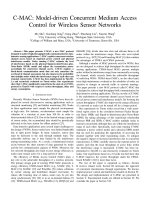
Fig 4: LM 35 Temperature sensor
In this paper we use LM35 as a temperature sensor. LM35 is a precision IC temperature sensor with its output
proportional to the temperature (in 0C).
The sensor circuitry is sealed and therefore it is not subjected to oxidation and other processes. With LM35,
temperature can be measured more accurately than with a thermistor. It also possesses low self heating and does not
cause more than 0.10C temperature rise in still air. The operating temperature range is from -550C to 1500C. The output
voltage varies by 10mV in response to every 0C rise/fall in ambient temperature i.e., its scale factor is 0.01V/ 0C.
2. Function of pressure sensor
Pressure sensor is uses to measure the pressure in the steam. It measures the amount the amount of force
applied on a unit area. There are different types of pressure sensors are available for power plant operation. In this
paper we are going to use BMP180 High Precision Digital Barometric Pressure Sensor Board Module. Specifications
of this sensor is
Pressure range
: 300 to1100 HPA (Elevation: 500m to 9000m)
Power supply voltage
: 1.8V to 3.6V (VDDA), 1.62V to 3.6V (VDDD)
LCC8 package
: Lead-free ceramic carrier package
Size
: 3.6mmx3.8x0.93mm
Low power consumption, high accuracy, low power mode.
Fig 5: Pressure sensor
Copyright to IJIRSET
DOI: 10.15680/IJIRSET.2014.0312038
www.ijirset.com
18043
ISSN: 2319-8753
International Journal of Innovative Research in Science,
Engineering and Technology
(An ISO 3297: 2007 Certified Organization)
Vol. 3, Issue 12, December 2014
In this paper we use BMP180 pressure sensor shown in figure. Various applications include Precise GPS
navigation, Indoor and outdoor navigation leisure, sport and health monitoring, weather forecast, vertical speed
indicator.
3. Function of Level sensor
Level sensors detect the level of substances that flow, including liquids, slurries, granular materials, and
powders. All such substances flow to become essentially level in their containers (or other physical boundaries)
because of gravity. The substance to be measured can be inside a container or can be in its natural form (e.g. a river or a
lake).
The level measurement can be either continuous or point values. Continuous level sensors measure level
within a specified range and determine the exact amount of substance in a certain place, while point-level sensors only
indicate whether the substance is above or below the sensing point. Generally the latter detect levels that are
excessively high or low.
Fig 6: Level sensor
Also important are the application constraints: price, accuracy, appearance, response rate, ease of calibration
or programming, physical size and mounting of the instrument, monitoring and control of continuous or discrete (point)
levels.
4. Function of Flow sensor
Flow sensor is used to measure the flow of steam from boiler drum to the turbine. In this paper we are going to
use the rotor flow sensor.
Fig 7: Flow sensor
The flow sensor is shown in figure. Main specifications of flow sensor is
Bright, Visual indication with choice output
Flow range from 1 LPM to 227 LPM
5. Function of RPM sensor
RPM sensor is used to measure the number of rotations that a turbine moving shaft will rotate per minute. In
this paper we are going to use AM4096 magnetic encoder chip from Renishaw shown in figure.
Copyright to IJIRSET
DOI: 10.15680/IJIRSET.2014.0312038
www.ijirset.com
18044
ISSN: 2319-8753
International Journal of Innovative Research in Science,
Engineering and Technology
(An ISO 3297: 2007 Certified Organization)
Vol. 3, Issue 12, December 2014
Fig 8: RPM Sensor
All of the sensor and processing electronics have been placed within the compact silicon design. The rotation
of a simple north/south magnet is picked up by the AM4096’s sensor and provides absolute positional information
output to an accuracy of better than 0.1 degree.
6. Function of PH sensor
The most common PH sensor is the glass electrode. It is used in many industry applications and in a wide
variety of fields. The glass-electrode method has a high reproducibility, and it can measure PH of various solutions.
Here we are using an electro chemical PH sensor. A PH electrode is a potentiometric or electrochemical
sensor that has a voltage output.
Fig 9: PH Sensor
A potentiometric sensor consists of two electrochemical cells or electrodes.
The glass electrode, sometimes called the measuring electrode or active electrode
And the reference electrode.
The electric potential created between the glass electrode, and the reference electrode is a function of the PH
value of the measured solution. So once the potential difference has been measured, we can calculate the PH value.
7. Function of Voltage sensor
The interface of various sensors to a controller like the Brain Stem GP 1.0 module typically involves either
conditioning or converting voltage levels in the range the controller requires.
Fig 10: Voltage Sensor
Copyright to IJIRSET
DOI: 10.15680/IJIRSET.2014.0312038
www.ijirset.com
18045
ISSN: 2319-8753
International Journal of Innovative Research in Science,
Engineering and Technology
(An ISO 3297: 2007 Certified Organization)
Vol. 3, Issue 12, December 2014
Many systems use A/D converters to make the sensor value relevant in a program or data logging
configuration. These converters have a fixed range of voltages they can convert from with 0-5 volts being by far the
most common.
Sensors often create voltages in different ranges than those required by the controllers they are being
interfaced to which requires the conversion of one voltage to another. This conversion often breaks down into a
combination of one or more of three types- amplification, dividing and shifting.
8. Function of Vibration sensor
Vibration sensor is used to measure the number of vibrations produced in turbine in a given amount of time. In
this paper we are using Piezo disk vibration sensor shown in figure.
Fig 11: Vibration Sensor
The three parameters representing motion detected by vibration sensors are displacement, velocity and
acceleration. Selections of sensors depend on frequencies of interest and signal levels involved. If the RPM of the
turbine increases than the desired value, it produces heavy vibrations which cause great damage to the moving blades
of the turbine. So we should monitor the vibrations of the turbine periodically.
9. Function of ADC
In this paper we are using ADC0808 converters to convert the analog data coming from various sensors to
digital data. The ADC0808 data acquisition component is a monolithic CMOS device with an 8-bit analog-to-digital
converter, 8-channel multiplexer and microprocessor compatible control logic. The 8-bit A/D converter uses successive
approximation as the conversion technique. The converter features a high impedance chopper stabilized comparator, a
256R voltage divider with analog switch tree a successive approximation register.
The 8-channel multiplexer can directly access any of 8-single-ended analog signals. The device eliminates the
need for external zero and full-scale adjustments. Easy interfacing to microprocessors is provided by the latched and
decoded multiplexer address inputs and latched TTL TRI-STATE outputs. The design of the ADC0808, AD0809 has
been optimized by incorporating the most desirable aspects of several A/D conversion techniques. The ADC0808,
ADC0809 offers high speed, high accuracy, minimal temperature dependence, excellent long-term accuracy and
repeatability and consumes minimal power. These features make this device ideally suited to applications from process
and machine control to consumer and automotive applications.
10. Function of UART
A Universal Asynchronous Receiver/Transmitter is a type of “Asynchronous Receiver/Transmitter”, a piece of
computer hardware that translates between parallel and serial forms. UARTs are commonly used in conjunction with
other communication standards such as EIA RS-232.
Copyright to IJIRSET
DOI: 10.15680/IJIRSET.2014.0312038
www.ijirset.com
18046
ISSN: 2319-8753
International Journal of Innovative Research in Science,
Engineering and Technology
(An ISO 3297: 2007 Certified Organization)
Vol. 3, Issue 12, December 2014
A UART is usually an individual integrated circuit used for serial communication over a computer or
peripheral serial port. UARTs are now commonly included in microcontrollers. A dual UART or DUART combines
two UARTs into a single chip.
The UART controller is the key component of the serial communication subsystem of a computer. It takes
bytes of data and transmits individual bits in a sequential fashion. At the destination, a second UART re-assembles the
bits into complete bytes. Each UART contains a shift register which is the fundamental method of conversion between
serial and parallel forms.
11. Function of Attemperator
It is an output valve which spars cool water on boiler tubs when temperature of steam exceeds the breakpoint
range. The valve will be closed if the temperature is in required range. Temperature is directly proportional to the
pressure, which is if temperature increases pressure also increases.
12. Function of Coal Feeder
It is used to load coal in to the boiler. If the temperature and pressure is less then we should supply more coal
through coal feeder. If the temperature and pressure is low then we should decrease coal feeding.
13. Function of Atmospheric vent
If the level of steam in steam drums increases then the vent will be opened and steam flows in to atmosphere.
It decreases the level and flow of steam and rotation of turbine shaft.
14. Function of HP dosing pump
If the level of PH changes then this pump induce chemical in to water to balance the ph of steam.
V. APPLICATIONS
Wireless sensor networks are used in wide range of applications, mainly in monitoring and control of various
industries [5] [6]. Some of them include power plants, oil and gas, cold chain and machine health monitoring, in
pipelining etc [7].
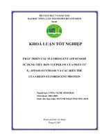
VI. EXPERIMENTAL RESULTS
If the sensors value exceeds, corresponding actuator will be turned ON or OFF as required and the parameters
are monitored in work space in a PC using Zigbee. The parameters mainly monitored are Temperature, Pressure, Flow,
Level and PH. The Visual Basic software is used to display the monitoring parameters in a PC.
Copyright to IJIRSET
DOI: 10.15680/IJIRSET.2014.0312038
www.ijirset.com
18047
ISSN: 2319-8753
International Journal of Innovative Research in Science,
Engineering and Technology
(An ISO 3297: 2007 Certified Organization)
Vol. 3, Issue 12, December 2014
Fig 12: Experimental Result
VII. CONCLUSION
The hardware and software design of an embedded monitoring system for real time applications is presented in
this paper. Vibration signals have been analyzed to detect the mechanical faults and necessary steps are taken to reduce
the faults. The implementations of analysis technique in time and frequency domain are given. The proposed system
sensor network based thermal power plant interlock control and remote monitoring system is verified with different levels
of severity.
REFERENCES
[1]
[2]
[3]
[4]
[5]
[6]
[7]
Donglin Wang, Member IEEE, Renlun He, Jiangqiu Han, Michel Fattoucho and Fadhel M. Ghonnouchi, Fellow, IEEE, “Sensor Network based
Oilwell Health Monitoring and Intelligent Control”, IEEE Sensors Journal, vol 12, No. 5, May 2012.
C.Rojiha, “Sensor Network Based Automatic Control System for Oil Pumping Unit Management”, International Journal of Scientific and
Research Publications, Volume 3, Issue 3, March 2013
Ganesh V. Padole, Sandip N. Kamble, “Embedded Wireless based Communication in Oilfield and Providing Security Syatem”, International
Journal Communication and Network Security (IJCNS), vol I, Issue II, 2011.
MQ-7 Semiconductor Sensor for Carbon Monoxide, Henan Hanwei Electronics Co., Ltd, www.hwsensor.com.
Sudararajan, V.; A. Redfern; M. Schneider; and P. Wright (2005). “Wireless Sensor Networks for Machinery Monitoring,” ASME International
Mechanical Engineering Congress and Exposition.
Wright, P.; D. Dornfeld; R. Hillaire; and N. Ota (2006). “Tool Temperature Measurement and its Integration within a Manufacturing System.”
Transactions of NAMRI/SME, Vol. 34, pp. 63-70.
Jagannath, V.M.D and B.Raman (2007). “ WiBeam: Wireless Bearing Monitoring System” communication systems software and Middleware,
COMSWARE 2007, 2nd International conference.
Copyright to IJIRSET
DOI: 10.15680/IJIRSET.2014.0312038
www.ijirset.com
18048