Tiêu chuẩn thí nghiệm dầu máy biến áp iec60156
Bạn đang xem bản rút gọn của tài liệu. Xem và tải ngay bản đầy đủ của tài liệu tại đây (1.38 MB, 41 trang )
Cong ty CP Thi Nghiem Dien Mien Nam Phung Nam Thanh.
IEC 60156:2018-08(en-fr)
Edition 3.0 2018-08
INTERNATIONAL
STANDARD
NORME
INTERNATIONALE
Insulating liquids – Determination of the breakdown voltage at power
frequency – Test method
Isolants liquides – Détermination de la tension de claquage à fréquence
industrielle – Méthode d’essai
Copyrighted material licensed to Electricity of Vietnam by Clarivate Analytics (US) LLC, subscriptions.techstreet.com, downloaded on 2018-10-22 02:47:53 +0000 by
No further reproduction or distribution is permitted.
®
IEC 60156
All rights reserved. Unless otherwise specified, no part of this publication may be reproduced or utilized in any form
or by any means, electronic or mechanical, including photocopying and microfilm, without permission in writing from
either IEC or IEC's member National Committee in the country of the requester. If you have any questions about IEC
copyright or have an enquiry about obtaining additional rights to this publication, please contact the address below or
your local IEC member National Committee for further information.
Droits de reproduction réservés. Sauf indication contraire, aucune partie de cette publication ne peut être reproduite
ni utilisée sous quelque forme que ce soit et par aucun procédé, électronique ou mécanique, y compris la photocopie
et les microfilms, sans l'accord écrit de l'IEC ou du Comité national de l'IEC du pays du demandeur. Si vous avez des
questions sur le copyright de l'IEC ou si vous désirez obtenir des droits supplémentaires sur cette publication, utilisez
les coordonnées ci-après ou contactez le Comité national de l'IEC de votre pays de résidence.
IEC Central Office
3, rue de Varembé
CH-1211 Geneva 20
Switzerland
Tel.: +41 22 919 02 11
www.iec.ch
About the IEC
The International Electrotechnical Commission (IEC) is the leading global organization that prepares and publishes
International Standards for all electrical, electronic and related technologies.
About IEC publications
The technical content of IEC publications is kept under constant review by the IEC. Please make sure that you have the
latest edition, a corrigenda or an amendment might have been published.
IEC Catalogue - webstore.iec.ch/catalogue
The stand-alone application for consulting the entire
bibliographical information on IEC International Standards,
Technical Specifications, Technical Reports and other
documents. Available for PC, Mac OS, Android Tablets and
iPad.
Electropedia - www.electropedia.org
The world's leading online dictionary of electronic and
electrical terms containing 21 000 terms and definitions in
English and French, with equivalent terms in 16 additional
languages. Also known as the International Electrotechnical
Vocabulary (IEV) online.
IEC publications search - webstore.iec.ch/advsearchform
The advanced search enables to find IEC publications by a
variety of criteria (reference number, text, technical
committee,…). It also gives information on projects, replaced
and withdrawn publications.
IEC Glossary - std.iec.ch/glossary
67 000 electrotechnical terminology entries in English and
French extracted from the Terms and Definitions clause of
IEC publications issued since 2002. Some entries have been
collected from earlier publications of IEC TC 37, 77, 86 and
CISPR.
IEC Customer Service Centre - webstore.iec.ch/csc
If you wish to give us your feedback on this publication or
need further assistance, please contact the Customer Service
Centre:
A propos de l'IEC
La Commission Electrotechnique Internationale (IEC) est la première organisation mondiale qui élabore et publie des
Normes internationales pour tout ce qui a trait à l'électricité, à l'électronique et aux technologies apparentées.
A propos des publications IEC
Le contenu technique des publications IEC est constamment revu. Veuillez vous assurer que vous possédez l’édition la
plus récente, un corrigendum ou amendement peut avoir été publié.
Catalogue IEC - webstore.iec.ch/catalogue
Application autonome pour consulter tous les renseignements
bibliographiques
sur
les
Normes
internationales,
Spécifications techniques, Rapports techniques et autres
documents de l'IEC. Disponible pour PC, Mac OS, tablettes
Android et iPad.
Electropedia - www.electropedia.org
Recherche de publications IEC webstore.iec.ch/advsearchform
La recherche avancée permet de trouver des publications IEC
en utilisant différents critères (numéro de référence, texte,
comité d’études,…). Elle donne aussi des informations sur les
projets et les publications remplacées ou retirées.
Glossaire IEC - std.iec.ch/glossary
67 000 entrées terminologiques électrotechniques, en anglais
et en français, extraites des articles Termes et Définitions des
publications IEC parues depuis 2002. Plus certaines entrées
antérieures extraites des publications des CE 37, 77, 86 et
CISPR de l'IEC.
IEC Just Published - webstore.iec.ch/justpublished
Service Clients - webstore.iec.ch/csc
Restez informé sur les nouvelles publications IEC. Just
Published détaille les nouvelles publications parues.
Disponible en ligne et aussi une fois par mois par email.
Si vous désirez nous donner des commentaires sur cette
publication ou si vous avez des questions contactez-nous:
Le premier dictionnaire en ligne de termes électroniques et
électriques. Il contient 21 000 termes et définitions en anglais
et en français, ainsi que les termes équivalents dans 16
langues additionnelles. Egalement appelé Vocabulaire
Electrotechnique International (IEV) en ligne.
Cong ty CP Thi Nghiem Dien Mien Nam Phung Nam Thanh.
IEC Just Published - webstore.iec.ch/justpublished
Stay up to date on all new IEC publications. Just Published
details all new publications released. Available online and
also once a month by email.
Copyrighted material licensed to Electricity of Vietnam by Clarivate Analytics (US) LLC, subscriptions.techstreet.com, downloaded on 2018-10-22 02:47:53 +0000 by
No further reproduction or distribution is permitted.
THIS PUBLICATION IS COPYRIGHT PROTECTED
Copyright © 2018 IEC, Geneva, Switzerland
Edition 3.0 2018-08
INTERNATIONAL
STANDARD
NORME
INTERNATIONALE
Insulating liquids – Determination of the breakdown voltage at power
frequency – Test method
Isolants liquides – Détermination de la tension de claquage à fréquence
industrielle – Méthode d’essai
Cong ty CP Thi Nghiem Dien Mien Nam Phung Nam Thanh.
INTERNATIONAL
ELECTROTECHNICAL
COMMISSION
COMMISSION
ELECTROTECHNIQUE
INTERNATIONALE
ICS 29.040
ISBN 978-2-8322-5959-7
Warning! Make sure that you obtained this publication from an authorized distributor.
Attention! Veuillez vous assurer que vous avez obtenu cette publication via un distributeur agréé.
® Registered trademark of the International Electrotechnical Commission
Marque déposée de la Commission Electrotechnique Internationale
Copyrighted material licensed to Electricity of Vietnam by Clarivate Analytics (US) LLC, subscriptions.techstreet.com, downloaded on 2018-10-22 02:47:53 +0000 by
No further reproduction or distribution is permitted.
®
IEC 60156
IEC 60156:2018 © IEC 2018
CONTENTS
FOREWORD ......................................................................................................................... 4
INTRODUCTION ................................................................................................................... 6
1
Scope ............................................................................................................................ 7
2
Normative references..................................................................................................... 7
3
Terms and definitions .................................................................................................... 7
4
Electrical apparatus ....................................................................................................... 7
4.1
4.2
4.3
4.4
4.5
4.6
5
Test
General ................................................................................................................. 7
Voltage regulator ................................................................................................... 7
Step-up transformer .............................................................................................. 8
Switching system .................................................................................................. 8
Current-limiting resistors ....................................................................................... 8
Measuring system ................................................................................................. 8
assembly ............................................................................................................... 8
5.1
General ................................................................................................................. 8
5.2
Test cell ................................................................................................................ 9
5.3
Electrodes............................................................................................................. 9
5.4
Stirring device ..................................................................................................... 10
6
Preparation of electrodes ............................................................................................. 10
7
Test assembly preparation ........................................................................................... 10
8
Sampling ..................................................................................................................... 11
9
Test procedure ............................................................................................................ 11
9.1
Sample preparation ............................................................................................. 11
9.2
Filling of the cell .................................................................................................. 11
10 Application of the voltage ............................................................................................. 11
Report ......................................................................................................................... 12
12
Test data dispersion and reproducibility ....................................................................... 12
12.1 Test data dispersion ............................................................................................ 12
12.2 Reproducibility .................................................................................................... 13
Annex A (informative) Improved test method ...................................................................... 14
A.1
Test procedure for improved test method ............................................................. 14
A.2
Report ................................................................................................................ 15
Annex B (informative) Special test methods for low volume samples ................................... 16
B.1
Low volume sample test ...................................................................................... 16
Annex C (informative) Representative material for a performance test ................................. 18
Bibliography ....................................................................................................................... 19
Figure 1 – Examples of test cells with spherical electrodes 12,5 mm to 13,0 mm
diameter ............................................................................................................................... 9
Figure 2 – Examples of test cells with partially spherical electrodes with 25 mm radius
and diameter of 36 mm ......................................................................................................... 9
Figure 3 – Graphical representation of coefficient of variation versus mean breakdown
voltage ............................................................................................................................... 13
Figure A.1 – Example of a sequence of breakdown shots for determination of the
breakdown voltage .............................................................................................................. 15
Cong ty CP Thi Nghiem Dien Mien Nam Phung Nam Thanh.
11
Copyrighted material licensed to Electricity of Vietnam by Clarivate Analytics (US) LLC, subscriptions.techstreet.com, downloaded on 2018-10-22 02:47:53 +0000 by
No further reproduction or distribution is permitted.
–2–
–3–
Figure B.1 – Example of low volume test cell, fixed electrode distance of 2 mm with
2 ml active volume under dielectric stress ........................................................................... 16
Figure B.2 – Example of low volume test cell, fixed electrode distance of 2,5 mm
(150 ml to 200 ml) ............................................................................................................... 17
Copyrighted material licensed to Electricity of Vietnam by Clarivate Analytics (US) LLC, subscriptions.techstreet.com, downloaded on 2018-10-22 02:47:53 +0000 by
No further reproduction or distribution is permitted.
IEC 60156:2018 © IEC 2018
Cong ty CP Thi Nghiem Dien Mien Nam Phung Nam Thanh.
IEC 60156:2018 © IEC 2018
INTERNATIONAL ELECTROTECHNICAL COMMISSION
____________
INSULATING LIQUIDS – DETERMINATION OF THE BREAKDOWN
VOLTAGE AT POWER FREQUENCY – TEST METHOD
FOREWORD
1) The International Electrotechnical Commission (IEC) is a worldwide organization for standardization comprising
all national electrotechnical committees (IEC National Committees). The object of IEC is to promote
international co-operation on all questions concerning standardization in the electrical and electronic fields. To
this end and in addition to other activities, IEC publishes International Standards, Technical Specifications,
Technical Reports, Publicly Available Specifications (PAS) and Guides (hereafter referred to as “IEC
Publication(s)”). Their preparation is entrusted to technical committees; any IEC National Committee interested
in the subject dealt with may participate in this preparatory work. International, governmental and nongovernmental organizations liaising with the IEC also participate in this preparation. IEC collaborates closely
with the International Organization for Standardization (ISO) in accordance with conditions determined by
agreement between the two organizations.
2) The formal decisions or agreements of IEC on technical matters express, as nearly as possible, an international
consensus of opinion on the relevant subjects since each technical committee has representation from all
interested IEC National Committees.
3) IEC Publications have the form of recommendations for international use and are accepted by IEC National
Committees in that sense. While all reasonable efforts are made to ensure that the technical content of IEC
Publications is accurate, IEC cannot be held responsible for the way in which they are used or for any
misinterpretation by any end user.
4) In order to promote international uniformity, IEC National Committees undertake to apply IEC Publications
transparently to the maximum extent possible in their national and regional publications. Any divergence
between any IEC Publication and the corresponding national or regional publication shall be clearly indicated in
the latter.
5) IEC itself does not provide any attestation of conformity. Independent certification bodies provide conformity
assessment services and, in some areas, access to IEC marks of conformity. IEC is not responsible for any
services carried out by independent certification bodies.
6) All users should ensure that they have the latest edition of this publication.
8) Attention is drawn to the Normative references cited in this publication. Use of the referenced publications is
indispensable for the correct application of this publication.
9) Attention is drawn to the possibility that some of the elements of this IEC Publication may be the subject of
patent rights. IEC shall not be held responsible for identifying any or all such patent rights.
International Standard IEC 60156 has been prepared by IEC technical committee TC 10:
Fluids for electrotechnical applications.
This third edition cancels and replaces the second edition published in 1995. This edition
constitutes a technical revision and, mainly, confirms the content of the previous edition even
if some advances are included. The test method has not been changed for practical reason
due to the very large number of instrumentation disseminated around the world, although the
use of stirring is now recommended.
The text of this International Standard is based on the following documents:
FDIS
Report on voting
10/1061/FDIS
10/1065/RVD
Full information on the voting for the approval of this International Standard can be found in
the report on voting indicated in the above table.
Cong ty CP Thi Nghiem Dien Mien Nam Phung Nam Thanh.
7) No liability shall attach to IEC or its directors, employees, servants or agents including individual experts and
members of its technical committees and IEC National Committees for any personal injury, property damage or
other damage of any nature whatsoever, whether direct or indirect, or for costs (including legal fees) and
expenses arising out of the publication, use of, or reliance upon, this IEC Publication or any other IEC
Publications.
Copyrighted material licensed to Electricity of Vietnam by Clarivate Analytics (US) LLC, subscriptions.techstreet.com, downloaded on 2018-10-22 02:47:53 +0000 by
No further reproduction or distribution is permitted.
–4–
–5–
This document has been drafted in accordance with the ISO/IEC Directives, Part 2.
The committee has decided that the contents of this document will remain unchanged until the
stability date indicated on the IEC website under "" in the data related to
the specific document. At this date, the document will be
•
reconfirmed,
•
withdrawn,
•
replaced by a revised edition, or
•
amended.
Copyrighted material licensed to Electricity of Vietnam by Clarivate Analytics (US) LLC, subscriptions.techstreet.com, downloaded on 2018-10-22 02:47:53 +0000 by
No further reproduction or distribution is permitted.
IEC 60156:2018 © IEC 2018
Cong ty CP Thi Nghiem Dien Mien Nam Phung Nam Thanh.
IEC 60156:2018 © IEC 2018
INTRODUCTION
As normally applied, breakdown voltage of insulating liquids is not a basic material property
but an empirical test procedure intended to indicate the presence of contaminants such as
water and solid suspended matter and the advisability of carrying out a drying and filtration
treatment.
The AC breakdown voltage value of insulating liquids strongly depends on the particular set of
conditions used in its measurement. Therefore, standardized testing procedures and
equipment are essential for the unambiguous interpretation of test results.
The method described in this document applies to either acceptance tests on new deliveries
of insulating liquids, or testing of treated liquids prior to or during filling into electrical
equipment, or to the monitoring and maintenance of oil-filled apparatus in service. It specifies
rigorous sample-handling procedures and temperature control that should be adhered to when
certified results are required. For routine tests, especially in the field, less stringent
procedures may be practicable and it is the responsibility of the user to determine their effect
on the results.
Annex A (informative) describes, for comparison, an alternative test method which could be
introduced in the future. Annex B (informative) describes special test methods, using cells
which may include low volume samples. Annex C (informative) describes a reference material
for a performance test and check according to IEC 60060-3[1] 1.
Copyrighted material licensed to Electricity of Vietnam by Clarivate Analytics (US) LLC, subscriptions.techstreet.com, downloaded on 2018-10-22 02:47:53 +0000 by
No further reproduction or distribution is permitted.
–6–
Cong ty CP Thi Nghiem Dien Mien Nam Phung Nam Thanh.
—————————
1
Numbers in square brackets refer to the Bibliography.
–7–
INSULATING LIQUIDS – DETERMINATION OF THE BREAKDOWN
VOLTAGE AT POWER FREQUENCY – TEST METHOD
1
Scope
This document specifies the method for determining the dielectric breakdown voltage of
insulating liquids at power frequency. The test procedure is performed in a specified
apparatus, where the oil sample is subjected to an increasing AC electrical field until
breakdown occurs. The method applies to all types of insulating liquids of nominal viscosity
up to 350 mm 2 /s at 40 °C. It is appropriate both for acceptance testing on unused liquids at
the time of their delivery and for establishing the condition of samples taken in monitoring and
maintenance of equipment.
2
Normative references
The following documents are referred to in the text in such a way that some or all of their
content constitutes requirements of this document. For dated references, only the edition
cited applies. For undated references, the latest edition of the referenced document (including
any amendments) applies.
IEC 60475, Method of sampling insulating liquids
3
Terms and definitions
No terms and definitions are listed in this document.
ISO and IEC maintain terminological databases for use in standardization at the following
addresses:
IEC Electropedia: available at />
•
ISO Online browsing platform: available at />
4
Electrical apparatus
4.1
General
The electrical apparatus consists of the following units:
1) voltage regulator,
2) step-up transformer,
3) switching system,
4) current-limiting resistors,
5) measuring device.
Two or more of these units may be integrated in any equipment system.
4.2
Voltage regulator
The test voltage shall be increased with an automatic control of the required uniform voltage
rate of rise. The device should not introduce harmonics disturbances (< 3%) and the AC
source should be free from harmonics.
Cong ty CP Thi Nghiem Dien Mien Nam Phung Nam Thanh.
•
Copyrighted material licensed to Electricity of Vietnam by Clarivate Analytics (US) LLC, subscriptions.techstreet.com, downloaded on 2018-10-22 02:47:53 +0000 by
No further reproduction or distribution is permitted.
IEC 60156:2018 © IEC 2018
4.3
IEC 60156:2018 © IEC 2018
Step-up transformer
The test voltage is obtained by using a step-up or resonant transformer supplied from an AC
source using 48 Hz to 62 Hz (sinusoidal waveform). The voltage source value is constantly
increased. The controls of the variable low-voltage source shall be capable of varying the test
voltage smoothly, uniformly and without overshoots or transients. Incremental increases
(produced, for example, by a variable auto-transformer or an amplifier) shall not exceed 2 %
of the expected breakdown voltage.
The centre-point of the secondary winding of the transformer should be connected to earth.
4.4
Switching system
The circuit shall be opened automatically if a sustained arc between the electrodes occurs
and the voltage between the electrodes collapses to a voltage less than 500 V. The primary
circuit of the step-up transformer shall be fitted with a circuit-breaker operated by the current
sensing device, resulting from the breakdown of the sample and shall break the voltage within
10 ms.
The sensitivity of the current or voltage sensing element depends on the energy-limiting
device employed and only approximate guidance can be given.
A cut-off time of < 100 µs, as given in the previous edition of this document, is needed to
perform multiple breakdowns on silicone liquids.
4.5
Current-limiting resistors
To protect the equipment and to avoid excessive decomposition at the instant of breakdown of
liquids such as silicone or ester liquids, a resistance limiting the breakdown current shall be
inserted in series with the test cell.
The short-circuit current of the transformer and associated circuits shall be within the range of
10 mA to 25 mA for all voltages higher than 15 kV. This may be achieved by a combination of
resistors in either or both the primary and secondary circuits of the high-voltage transformer.
Measuring system
For the purposes of this document, the magnitude of the test voltage is defined as its peak
value divided by
2.
The output voltage of the step-up transformer may be measured by means of a measuring
system consisting of a voltage divider or a measuring winding of the step-up transformer
coupled with a peak-voltmeter. The measuring system shall be calibrated up to the upper
scale voltage to be measured. A method of calibration which has been found satisfactory is
the use of a transfer standard. This is an auxiliary measuring device which is connected in
place of the test cell between the high-voltage terminals to which it presents an impedance
similar to the one of the sample liquid. The auxiliary device is separately calibrated against a
primary standard [2],[3].
5
5.1
Test assembly
General
The breakdown voltage test is performed following the method described herewith as a
routine test.
Cong ty CP Thi Nghiem Dien Mien Nam Phung Nam Thanh.
4.6
Copyrighted material licensed to Electricity of Vietnam by Clarivate Analytics (US) LLC, subscriptions.techstreet.com, downloaded on 2018-10-22 02:47:53 +0000 by
No further reproduction or distribution is permitted.
–8–
5.2
–9–
Test cell
The volume of the cell shall be between 350 ml and 600 ml.
The cell shall be made from electrically insulating materials, that are not hygroscopic. The cell
shall be transparent and chemically inert, resistant to the insulating liquid and to the cleaning
agent that shall be used. A glass cell is the preferred option.
The cell shall be provided with a cover and shall be designed to permit easy removal of the
electrodes for cleaning and maintenance. To improve homogenization of the test liquid, a
rounded bottom shape of the cell is recommended. Containers and covers shall be cleaned by
washing with a suitable solvent or clean insulating liquid to remove residues of an earlier
sample. After cleaning, containers shall be immediately capped and kept closed until used
again. Electrodes shall be stored in clean insulating liquids.
NOTE
It is preferable, in the case of esters, to use similar liquid to store the electrodes.
Examples of suitable cell designs are given in Figures 1 and 2.
Dimensions in millimetres
2,5
IEC
NOTE The stirring device can be mounted on the top (right side figure) or on the bottom (left side figure). The
stirring device position and Vernier shifter are reported only as reference.
Dimensions in millimetres
ø36
R25
2,5
20
IEC
NOTE The stirring device can be mounted on the top (right side figure) or on the bottom (left side figure). The
stirring device position and Vernier shifter are reported only as reference.
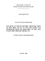
Figure 2 – Examples of test cells with partially spherical electrodes
with 25 mm radius and diameter of 36 mm
5.3
Electrodes
The electrodes shall be made either of brass, bronze or austenitic stainless steel. They shall
be polished and, in shape, either spherical (12,5 mm to 13,0 mm diameter) as shown in
Figure 1 or in partially spherical shape (25 mm ± 0,25 mm radius) as shown in Figure 2. The
axis of the electrode system shall be horizontal and shall be at least 40 mm below the surface
Cong ty CP Thi Nghiem Dien Mien Nam Phung Nam Thanh.
Figure 1 – Examples of test cells with spherical electrodes
12,5 mm to 13,0 mm diameter
Copyrighted material licensed to Electricity of Vietnam by Clarivate Analytics (US) LLC, subscriptions.techstreet.com, downloaded on 2018-10-22 02:47:53 +0000 by
No further reproduction or distribution is permitted.
IEC 60156:2018 © IEC 2018
IEC 60156:2018 © IEC 2018
of the test liquid. Any part of the cell or stirrer shall not influence the electric field between the
electrodes. The gap between the electrodes shall be 2,50 mm ± 0,05 mm.
The electrodes shall be examined frequently for pitting or other damage and shall be
maintained or replaced as soon as such damage is observed.
NOTE The electrodes can be replaced or refurbished typically after 5 000 single breakdowns. The surface of the
electrodes can be polished with a maximum grain diameter of 10 µm. The limit of the arithmetical mean deviation of
the roughness profile of the electrodes can be Ra ≤ 0,5 µm, according to ISO 4287[4].
5.4
Stirring device
The use of an automatic stirring device is recommended, to be used at all times throughout
the test.
The stirrer shall be mounted in the test cell in order to maximize the homogenization of the
liquid. It shall be designed so that it is easily cleaned. Stirring shall be achieved by means of
a two-bladed or appropriate stirrer of effective diameter 25 mm to 35 mm, axial depth 5 mm to
10 mm, rotating at a speed of 200 r/min to 300 r/min. The stirrer shall not produce air bubbles.
It shall be fully immersed in the liquid sample. Examples of stirring systems mounted in test
cells are reported in Figures 1 and 2.
NOTE 1 To avoid bubbles between the electrodes the stirrer can rotate preferably in such a direction that bubbles
can be removed [5].
NOTE 2 The stirring device can be mounted on the top or on the bottom. In Figures 1 and 2, the stirring device
position is reported only as reference.
NOTE 3
6
A magnetic stirring device can be also used.
Preparation of electrodes
New electrodes shall be cleaned and fulfil the requirements of 5.3. Preparation of the
electrodes shall be according to the following procedure:
clean all surfaces with a suitable volatile solvent and allow the solvent to evaporate;
–
polish with fine abrasive powder (for example, jeweller’s rouge) or abrasive paper or cloth,
for example crocus cloth (see 5.3);
–
after polishing, clean with petroleum spirit (reagent quality: boiling range of about 40 °C to
80 °C) followed by acetone (reagent quality);
–
assemble the electrodes in the cell, fill with a clean, unused insulating liquid of the type to
be tested;
–
before the first breakdown test, raise the voltage until breakdown 24 times.
This procedure shall be repeated after each cleaning or change of electrodes.
7
Test assembly preparation
It is recommended that a separate test cell assembly be reserved for different insulating liquid
types.
Test assemblies shall be stored in a dry place, covered and filled with dry insulating liquid of
the type in regular use in the cell.
On change of the type of liquid under test, remove all residues of the previous liquid with an
appropriate solvent, rinse the assembly with a clean, dry liquid of the same type as the one to
be tested, drain and refill.
Cong ty CP Thi Nghiem Dien Mien Nam Phung Nam Thanh.
–
Copyrighted material licensed to Electricity of Vietnam by Clarivate Analytics (US) LLC, subscriptions.techstreet.com, downloaded on 2018-10-22 02:47:53 +0000 by
No further reproduction or distribution is permitted.
– 10 –
8
– 11 –
Sampling
Sampling shall be carried out in accordance with IEC 60475.
NOTE Breakdown voltage is extremely sensitive to the slightest contamination of the sample by water and
particulate matter. Special precautions can be implemented to avoid contamination of the sample and the need for
trained personnel and experienced supervision. Unless otherwise required, the sample is taken where the liquid is
likely to be most contaminated, usually at the lowest point of the container holding it.
The test is carried out, unless otherwise specified, on the sample as received without drying
or degassing.
9
9.1
Test procedure
Sample preparation
Immediately before filling the test cell, the sample container is gently agitated and turned over
several times in such a way as to ensure, as far as possible, a homogeneous distribution of
the impurities contained in the liquid without causing the formation of air bubbles.
A possible method is an automatic rotation of the sample container horizontally for 1 min with
a recommended speed of 30 r/min.
Equilibrate the sample to room temperature. Unnecessary exposure to the ambient air of the
sample shall be avoided.
9.2
Filling of the cell
Immediately before commencing the test, drain the test cell and rinse the walls, electrodes
and other component parts, with the test liquid. Drain and slowly fill with the test liquid
avoiding the formation of air bubbles.
Measure and record the temperature of the liquid.
At the time of test, the temperatures shall be maintained at room temperature (20 °C ± 5 °C).
Adjust the electrode gap distance to 2,5 mm ± 0,05 mm with a vernier or other system and
start the stirrer. The stirrer, if used, shall run continuously throughout the test.
Metallic gauges can damage the surface of the electrodes; hence, they have to be avoided.
The first application of voltage is started approximately 5 min after completion of filling and
checking that no air bubbles are visible in the electrode gap. Apply voltage to the electrodes
and uniformly increase voltage from zero at the rate of 2,0 kV/s ± 0,2 kV/s until breakdown
occurs.
The breakdown voltage is the maximum voltage reached at the time the circuit is opened
either automatically (established arc) or manually (visible or audible discharge detected).
Record the value in kilovolts.
Carry out six breakdowns on the same cell filling allowing a pause of at least 2 min after each
breakdown before re-application of voltage. Check that no gas bubbles are present within the
electrode gap.
Cong ty CP Thi Nghiem Dien Mien Nam Phung Nam Thanh.
10 Application of the voltage
Copyrighted material licensed to Electricity of Vietnam by Clarivate Analytics (US) LLC, subscriptions.techstreet.com, downloaded on 2018-10-22 02:47:53 +0000 by
No further reproduction or distribution is permitted.
IEC 60156:2018 © IEC 2018
IEC 60156:2018 © IEC 2018
Calculate the mean value of the six breakdowns, standard deviation and related coefficient of
variation (ratio between standard deviation and mean breakdown voltage).
For insulating liquids having a nominal viscosity higher than 15 mm 2 /s (40°C), the resting time
before application of the voltage shall be increased in the range of 15 min to 30 min. In
addition, the resting time between two consecutive shots shall also be increased accordingly.
11 Report
The report shall include:
–
sample identification, possibly including the type of insulating liquids;
–
value of each individual breakdown in kilovolts;
–
mean breakdown value;
–
type of electrodes used;
–
temperature of the liquid (in the test cell);
–
coefficient of variation (%) (optional);
–
frequency of the test voltage (optional);
–
stirring arrangement (optional).
In the case where the individual breakdown voltage is above the maximum equipment voltage
capability, the result shall be reported as greater than the maximum voltage capability
(example: > 80 kV).
12 Test data dispersion and reproducibility
12.1
Test data dispersion
Typical coefficients of variation reported in Figure 3 are for information only and do not
represent an acceptance criteria for the obtained results.
Cong ty CP Thi Nghiem Dien Mien Nam Phung Nam Thanh.
The graphical representation of Figure 3 indicates the values of the coefficient of variation
and its mean value which have been found in a large body of test data in several laboratories
using transformer liquids. The solid line in the graph shows the distribution of the coefficient
of variation as a function of the mean breakdown value. The dotted lines indicate the
expected 2,5 % (0,025) to 97,5 % (0,975) range of values of standard deviation (SD)/mean as
a function of the value of the mean.
Copyrighted material licensed to Electricity of Vietnam by Clarivate Analytics (US) LLC, subscriptions.techstreet.com, downloaded on 2018-10-22 02:47:53 +0000 by
No further reproduction or distribution is permitted.
– 12 –
Coefficient of variation (%)
– 13 –
50
40
30
97,5 %
%
20
50 %
10
2,5 %
0
0
20
40
60
80
100
Mean breakdown voltage (kV)
IEC
Figure 3 – Graphical representation of coefficient of variation versus
mean breakdown voltage
12.2
Reproducibility
Experience has shown that the reproducibility of individual dielectric breakdown values is in
the range of ±30 %.
Copyrighted material licensed to Electricity of Vietnam by Clarivate Analytics (US) LLC, subscriptions.techstreet.com, downloaded on 2018-10-22 02:47:53 +0000 by
No further reproduction or distribution is permitted.
IEC 60156:2018 © IEC 2018
Cong ty CP Thi Nghiem Dien Mien Nam Phung Nam Thanh.
IEC 60156:2018 © IEC 2018
Annex A
(informative)
Improved test method
A.1
Test procedure for improved test method
Annex A describes an improved test method, believed to be able to reduce the scatter of the
results of breakdown voltage, which may be used [5],[6],[7]. The results obtained using both
methods around the world during the following years will assist in a future choice when this
document is revised.
Use the same instrument and prepare the test according to Clauses 4 to 9. Instead of the
procedure described in Clause 10, follow the procedure described hereafter (Figure A.1):
NOTE
The software of the device can be aligned with the procedure described in Annex A.
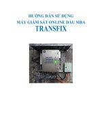
1) The first application of voltage is started at least 5 min after completion of filling and after
checking that the liquid under test is free from air bubbles.
2) Apply voltage to the electrodes uniformly and increase the voltage from zero at the rate of
2 kV/s ± 0,2 kV/s until 10 kV is reached.
3) Maintain the 10 kV level for 10 s, then continue with a rate of voltage rise of 2 kV/s ±
0,2 kV/s until a breakdown occurs.
4) The breakdown voltage shall be recorded at the maximum voltage reached.
5) Carry out 10 breakdowns on the same filling, allowing a pause of at least 1 min after each
breakdown before re-application of the test voltage. Record each single breakdown.
Calculate the test results as the average and coefficient of variation (ratio between
standard deviation and mean breakdown voltage) of the remaining six results after
disregarding the two highest and two lowest results.
For insulating liquids having a nominal viscosity higher than 15 mm 2 /s (40°C), the resting time
before application of the voltage shall be increased in the range of 15 min to 30 min. In
addition, the resting time between two consecutive shots shall also be increased accordingly.
Cong ty CP Thi Nghiem Dien Mien Nam Phung Nam Thanh.
6) When the coefficient of variation of the test result (mean breakdown voltage) exceeds the
upper limit (Figure 3), the test procedure should proceed for the other 10 breakdowns,
repeating the procedure from 2) to 6) with the same sample liquid. Record also the results
of these additional breakdowns. Calculate the test results as the average and coefficient
of variation of the remaining 12 results after disregarding the four highest and four lowest
results.
Copyrighted material licensed to Electricity of Vietnam by Clarivate Analytics (US) LLC, subscriptions.techstreet.com, downloaded on 2018-10-22 02:47:53 +0000 by
No further reproduction or distribution is permitted.
– 14 –
kV
– 15 –
Shot 1
80
Shot 8
Shot 5
70
Shot 4
Shot 2
60
40
20
10
Initial resting
time > 3 min
0
1
2
2 kV/s
Pre-energizing
10 s
30
3
Shot 10
Shot 3
≈3s
Shot 6
Shot 9
Shot 7
Resting time
2 kV/s
50
1 min
4
5
5 Sec
6
7
8
9
10
11
12
13
14
15
16
17
18
19
Time (minutes)
IEC
In the average calculation, the results of four outliers (two highest and two lowest values) have to be discarded (in
this example, shots 1 and 8 are the highest and shots 7 and 9 are the lowest).
Figure A.1 – Example of a sequence of breakdown shots for determination
of the breakdown voltage
A.2
Report
See Clause 11.
Copyrighted material licensed to Electricity of Vietnam by Clarivate Analytics (US) LLC, subscriptions.techstreet.com, downloaded on 2018-10-22 02:47:53 +0000 by
No further reproduction or distribution is permitted.
IEC 60156:2018 © IEC 2018
Cong ty CP Thi Nghiem Dien Mien Nam Phung Nam Thanh.
IEC 60156:2018 © IEC 2018
Annex B
(informative)
Special test methods for low volume samples
B.1
Low volume sample test
The special test method reported in this annex is suggested for use with low sample volumes.
A limited body of data has shown that the results obtained are comparable to the results
obtained from the method described in the main body of this document. Examples of the
reduced volume test cell are shown in Figures B.1 and B.2.
A fast test on-site may require small portable testers, able to measure the breakdown voltage
of insulating liquids (in either direct current or alternating current). An example of such
instruments is a Cockcroft-Walton generator, which utilizes a small electrode gap cell and
measuring instrumentation. The cell in such an instrument also requires very small quantities
of test liquid.
2
ø50
NOTE The results obtained with such portable instruments cannot be used for diagnostic purposes. Results can
differ significantly unless comparability has been established.
Key
1
partially spherical electrodes, rounded disk electrode, 50 mm diameter, 2 mm gap
2
oil filled cup, test cell HV insulation
3
cover
4
electrode distance control
5
sample inlet
6
sample outlet
Figure B.1 – Example of low volume test cell, fixed electrode distance of 2 mm with
2 ml active volume under dielectric stress
Cong ty CP Thi Nghiem Dien Mien Nam Phung Nam Thanh.
IEC
Copyrighted material licensed to Electricity of Vietnam by Clarivate Analytics (US) LLC, subscriptions.techstreet.com, downloaded on 2018-10-22 02:47:53 +0000 by
No further reproduction or distribution is permitted.
– 16 –
ø36
64
Dimensions in millimetres
2,5
Section A-A
64
IEC
Figure B.2 – Example of low volume test cell, fixed electrode distance of 2,5 mm
(150 ml to 200 ml)
Copyrighted material licensed to Electricity of Vietnam by Clarivate Analytics (US) LLC, subscriptions.techstreet.com, downloaded on 2018-10-22 02:47:53 +0000 by
No further reproduction or distribution is permitted.
– 17 –
IEC 60156:2018 © IEC 2018
R15
Cong ty CP Thi Nghiem Dien Mien Nam Phung Nam Thanh.
IEC 60156:2018 © IEC 2018
Annex C
(informative)
Representative material for a performance test
The reference analysis may be used as a performance check to prove that the test system is
fit for use according to IEC 60060-3.
The representative material shall be unused, filtered and degassed mineral, silicone or ester
liquids. The minimum quality requirement of the liquid shall be according to IEC relevant
standards.
If the test result does not reach the required > 70 kV value, check the functionality of the
equipment, or prepare a fresh representative material sample and carry out a new
performance check.
Copyrighted material licensed to Electricity of Vietnam by Clarivate Analytics (US) LLC, subscriptions.techstreet.com, downloaded on 2018-10-22 02:47:53 +0000 by
No further reproduction or distribution is permitted.
– 18 –
Cong ty CP Thi Nghiem Dien Mien Nam Phung Nam Thanh.
– 19 –
Bibliography
IEC 60060-3, High-voltage test techniques – Part 3: Definitions and requirements for
on-site testing
[2]
IEC 60052:2002, Voltage measurement by means of standard air gaps
[3]
IEC 60060-2:2010, High-voltage test techniques – Part 2: Measuring systems
[4]
ISO 4287, Geometrical Product Specifications (GPS) – Surface texture: Profile method
–Terms, definitions and surface texture parameters
[5]
Elektrische Festigkeit von Isolieröl, Dissertation von G. J. Pukel TU Graz, 2004,
ISBN 978-3-85133-060-1
[6]
M. Baur, M. Pompili, R. Bartnikas, “A comment on the test methods for the breakdown
voltage of dielectric liquids”, IEEE Trans. Dielectric Electric Insulation, Vol. 19,
p 1 482-1 484, 2012
[7]
M. Baur, L. Calcara, M. Pompili, “Scatter Reduction of the 50-60 Hz Breakdown
Voltage Test for Insulating Liquids”, IEEE Trans. Dielectric Electric Insulation, Vol. 22,
Issue 5, page 2401-2407, October 2015
[8]
M. Baur, J. Knauel, L. Calcara, M. Pompili, “Insulating Liquids Breakdown Voltage
Determination: Test Method Efficiency”, ICDL 2017, paper 1239, Manchester
[9]
T. J. Lewis, “Mechanism of electrical breakdown in saturated hydrocarbon liquids”,
Journal of Applied Physics, Vol. 27, pp. 645-650, 1956
[10]
E. O. Forster, “Critical Assessment of the Electrical Breakdown Process in Dielectric
Fluids”, IEEE Transactions on Electrical Insulation, Vol. 20, pp. 891-896, 1985
[11]
E.O. Forster, C. Mazzetti and M. Pompili “Electrical breakdown in dielectric fluids: a
review of old a new concept”, L’Energia Elettrica, Vol. LXVII, pp. 1-19, 1990
[12]
IEC 60296, Fluids for electrotechnical applications – Unused mineral insulating oils for
transformers and switchgear
[13]
IEC 60422, Mineral insulating oils in electrical equipment – Supervision and
maintenance guidance
___________
Cong ty CP Thi Nghiem Dien Mien Nam Phung Nam Thanh.
[1]
Copyrighted material licensed to Electricity of Vietnam by Clarivate Analytics (US) LLC, subscriptions.techstreet.com, downloaded on 2018-10-22 02:47:53 +0000 by
No further reproduction or distribution is permitted.
IEC 60156:2018 © IEC 2018
IEC 60156:2018 © IEC 2018
SOMMAIRE
AVANT-PROPOS ................................................................................................................ 22
INTRODUCTION ................................................................................................................. 24
1
Domaine d’application.................................................................................................. 25
2
Références normatives ................................................................................................ 25
3
Termes et définitions ................................................................................................... 25
4
Appareillage électrique ................................................................................................ 25
4.1
Généralités ......................................................................................................... 25
4.2
Régulateur de tension ......................................................................................... 25
4.3
Transformateur élévateur .................................................................................... 26
4.4
Disjoncteur.......................................................................................................... 26
4.5
Résistances de limitation de courant .................................................................... 26
4.6
Système de mesure............................................................................................. 26
5
Dispositif d’essai ......................................................................................................... 27
5.1
Généralités ......................................................................................................... 27
5.2
Cellule d’essai .................................................................................................... 27
5.3
Électrodes........................................................................................................... 28
5.4
Agitateur ............................................................................................................. 28
6
Préparation des électrodes .......................................................................................... 29
7
Préparation du dispositif d’essai ................................................................................... 29
8
Échantillonnage ........................................................................................................... 29
9
Procédure d’essai ........................................................................................................ 29
9.1
Préparation de l’échantillon ................................................................................. 29
9.2
Remplissage de la cellule .................................................................................... 30
10 Application de la tension .............................................................................................. 30
Rapport ....................................................................................................................... 30
12
Dispersion des résultats et reproductibilité ................................................................... 31
12.1 Dispersion des résultats ...................................................................................... 31
12.2 Reproductibilité ................................................................................................... 31
Annexe A (informative) Méthode d’essai améliorée ............................................................. 32
A.1
Procédure d’essai pour une méthode d’essai améliorée ....................................... 32
A.2
Rapport ............................................................................................................... 33
Annexe B (informative) Méthodes d’essai spéciales pour échantillons de faible volume ....... 34
B.1
Essai sur les échantillons de faible volume .......................................................... 34
Annexe C (informative) Matériau représentatif pour un essai de détermination des
caractéristiques ........................................................................................................... 36
Bibliographie ...................................................................................................................... 37
Figure 1 – Exemples de cellules d’essai avec des électrodes sphériques de diamètre
compris entre 12,5 mm et 13,0 mm ..................................................................................... 27
Figure 2 – Exemples de cellules d’essai avec des électrodes hémisphériques d’un
rayon de 25 mm et d’un diamètre de 36 mm ........................................................................ 28
Figure 3 – Représentation graphique du coefficient de variation en fonction de la
tension de claquage moyenne ............................................................................................. 31
Figure A.1 – Exemple d’une séquence de claquages pour la détermination de la
tension de claquage ............................................................................................................ 33
Cong ty CP Thi Nghiem Dien Mien Nam Phung Nam Thanh.
11
Copyrighted material licensed to Electricity of Vietnam by Clarivate Analytics (US) LLC, subscriptions.techstreet.com, downloaded on 2018-10-22 02:47:53 +0000 by
No further reproduction or distribution is permitted.
– 20 –
– 21 –
Figure B.1 – Exemple de cellule d’essai de faible volume, distance fixe entre
électrodes de 2 mm avec 2 ml de volume actif sous contrainte diélectrique .......................... 34
Figure B.2 – Exemple de cellule d’essai de faible volume, distance fixe entre
électrodes de 2,5 mm (150 ml à 200 ml) .............................................................................. 35
Copyrighted material licensed to Electricity of Vietnam by Clarivate Analytics (US) LLC, subscriptions.techstreet.com, downloaded on 2018-10-22 02:47:53 +0000 by
No further reproduction or distribution is permitted.
IEC 60156:2018 © IEC 2018
Cong ty CP Thi Nghiem Dien Mien Nam Phung Nam Thanh.
IEC 60156:2018 © IEC 2018
COMMISSION ÉLECTROTECHNIQUE INTERNATIONALE
____________
ISOLANTS LIQUIDES – DÉTERMINATION DE LA TENSION DE CLAQUAGE
À FRÉQUENCE INDUSTRIELLE – MÉTHODE D’ESSAI
AVANT-PROPOS
1) La Commission Électrotechnique Internationale (IEC) est une organisation mondiale de normalisation
composée de l'ensemble des comités électrotechniques nationaux (Comités nationaux de l’IEC). L’IEC a pour
objet de favoriser la coopération internationale pour toutes les questions de normalisation dans les domaines
de l'électricité et de l'électronique. À cet effet, l’IEC – entre autres activités – publie des Normes
internationales, des Spécifications techniques, des Rapports techniques, des Spécifications accessibles au
public (PAS) et des Guides (ci-après dénommés "Publication(s) de l’IEC"). Leur élaboration est confiée à des
comités d'études, aux travaux desquels tout Comité national intéressé par le sujet traité peut participer. Les
organisations internationales, gouvernementales et non gouvernementales, en liaison avec l’IEC, participent
également aux travaux. L’IEC collabore étroitement avec l'Organisation Internationale de Normalisation (ISO),
selon des conditions fixées par accord entre les deux organisations.
2) Les décisions ou accords officiels de l’IEC concernant les questions techniques représentent, dans la mesure
du possible, un accord international sur les sujets étudiés, étant donné que les Comités nationaux de l’IEC
intéressés sont représentés dans chaque comité d’études.
3) Les Publications de l’IEC se présentent sous la forme de recommandations internationales et sont agréées
comme telles par les Comités nationaux de l’IEC. Tous les efforts raisonnables sont entrepris afin que l’IEC
s'assure de l'exactitude du contenu technique de ses publications; l’IEC ne peut pas être tenue responsable de
l'éventuelle mauvaise utilisation ou interprétation qui en est faite par un quelconque utilisateur final.
4) Dans le but d'encourager l'uniformité internationale, les Comités nationaux de l’IEC s'engagent, dans toute la
mesure possible, à appliquer de façon transparente les Publications de l’IEC dans leurs publications nationales
et régionales. Toutes divergences entre toutes Publications de l’IEC et toutes publications nationales ou
régionales correspondantes doivent être indiquées en termes clairs dans ces dernières.
5) L’IEC elle-même ne fournit aucune attestation de conformité. Des organismes de certification indépendants
fournissent des services d'évaluation de conformité et, dans certains secteurs, accèdent aux marques de
conformité de l’IEC. L’IEC n'est responsable d'aucun des services effectués par les organismes de certification
indépendants.
6) Tous les utilisateurs doivent s'assurer qu'ils sont en possession de la dernière édition de cette publication.
8) L'attention est attirée sur les références normatives citées dans cette publication. L'utilisation de publications
référencées est obligatoire pour une application correcte de la présente publication.
9) L’attention est attirée sur le fait que certains des éléments de la présente Publication de l’IEC peuvent faire
l’objet de droits de brevet. L’IEC ne saurait être tenue pour responsable de ne pas avoir identifié de tels droits
de brevets et de ne pas avoir signalé leur existence.
La Norme internationale IEC 60156 a été établie par le comité d’études 10 de l’IEC: Fluides
pour applications électrotechniques.
Cette troisième édition annule et remplace la deuxième édition parue en 1995. Cette édition
constitue une révision technique et valide essentiellement le contenu de l’édition précédente
même si elle comporte certaines améliorations. La méthode d’essai n’a pas été modifiée pour
des raisons pratiques et du fait du très grand nombre de dispositifs de mesure utilisés au
niveau international, même si l’emploi de l’agitateur est maintenant recommandé.
Le texte de cette Norme internationale est issu des documents suivants:
FDIS
Rapport de vote
10/1061/FDIS
10/1065/RVD
Cong ty CP Thi Nghiem Dien Mien Nam Phung Nam Thanh.
7) Aucune responsabilité ne doit être imputée à l’IEC, à ses administrateurs, employés, auxiliaires ou
mandataires, y compris ses experts particuliers et les membres de ses comités d'études et des Comités
nationaux de l’IEC, pour tout préjudice causé en cas de dommages corporels et matériels, ou de tout autre
dommage de quelque nature que ce soit, directe ou indirecte, ou pour supporter les coûts (y compris les frais
de justice) et les dépenses découlant de la publication ou de l'utilisation de cette Publication de l’IEC ou de
toute autre Publication de l’IEC, ou au crédit qui lui est accordé.
Copyrighted material licensed to Electricity of Vietnam by Clarivate Analytics (US) LLC, subscriptions.techstreet.com, downloaded on 2018-10-22 02:47:53 +0000 by
No further reproduction or distribution is permitted.
– 22 –
– 23 –
Le rapport de vote indiqué dans le tableau ci-dessus donne toute information sur le vote ayant
abouti à l'approbation de cette Norme internationale.
Ce document a été rédigé selon les Directives ISO/IEC, Partie 2.
Le comité a décidé que le contenu de ce document ne sera pas modifié avant la date de
stabilité indiquée sur le site web de l’IEC sous «» dans les données
relatives au document recherché. À cette date, le document sera
•
reconduit,
•
supprimé,
•
remplacé par une édition révisée, ou
•
amendé.
Copyrighted material licensed to Electricity of Vietnam by Clarivate Analytics (US) LLC, subscriptions.techstreet.com, downloaded on 2018-10-22 02:47:53 +0000 by
No further reproduction or distribution is permitted.
IEC 60156:2018 © IEC 2018
Cong ty CP Thi Nghiem Dien Mien Nam Phung Nam Thanh.