Nghiên cứu xác định chế độ hàn điện xỉ áp lực tối ưu ứng dụng để hàn nối cốt thép tt tiếng anh
Bạn đang xem bản rút gọn của tài liệu. Xem và tải ngay bản đầy đủ của tài liệu tại đây (1.79 MB, 36 trang )
MINISTRY OF EDUCATION
AND TRAINING
MINISTRY OF INDUSTRY
AND TRADE
NATIONAL RESEARCH INSTITUTE
OF MECHANICAL ENGINEERING
Ph.D CANDIDATE. HOANG ĐUC LONG
RESEARCH TO DETEMINE THE OPTIMAL
PARAMETERS OF ELECTROSLAG PRESSURE
WELDING APPLIED TO WELDING
REINFORCEMENT
SPECIALIZATION: MECHANICAL ENGINEERING
CODE No: 9520103
SUMMARY OF ENGINEERING Ph.D THESIS
HA NOI - 2019
Training institutions: National Research Institute of Mechanical Engineering
– Ministry of Industry and Trade
Full name of the scientific supervisor:
1.
Assoc. Prof. Bui Van Hanh
2.
Assoc. Prof . Nguyen Chi Sang
Reviewer 1:
Reviewer 2:
Reviewer 3:
Proposal thesis was defended under scientific committee at National
Research Institute of Mechanical Engineering - Ministry of Industry and
Trade.
Address: No 4 Pham Van Dong road
Cau Giay district, Ha Noi city.
At ……am……, date …… month ….. year 2019
Reference at:
National library
Library of National Research Institute of Mechanical Engineering
Library of Ha Noi Universityof Science and Technology
INTRODUCTION
1. The urgency of the thesis
In the recent years, the constructions of skyscrapers, bridges, hydropower plants ... are
strongly developing in Vietnam. In particular, the connection of reinforcement at the construction
site is a very important stage, which greatly affecting the quality and economic efficiency of the
project.
Currently, a new welding process: Electroslag Pressure Welding (EPW) has been
initially applied to weld reinforcement with positive results and has noticeably wide application
potential. This process has many outstanding advantages overcoming the disadvantages of
previous methods. However, due to the limitation of researching scope and funding, the in-depth
scientific issues of this technology have not been studied thoroughly and systematically. The
processes of arc creating to form slag pool, heat transfer process, melting process and weld
forming are extremely complicated, which depends on welding parameter, such as: welding
current, welding voltage, welding time and welding pressure. Moreover, the parameters of
Electroslag Pressure Welding has not been studied intensively, especially the welding pressure
parameters (Ph) and welding time (Th ) are not suitable for each type of nominal reinforcement
diameter (ddn). In addition, the technology and specialized equipment have not been performed
well, especially without the national standard in this process. Therefore the quality of welds for
different types of reinforcement diameter has not been stable.
Due to the above mentioned reasons, it is evindent that a professional research to find
out the optimal value of Electroslag Pressure Welding parameters in order to improve the quality
and economic efficiency of reinforcing welds is an urgent issue and has high scientific and
practical significance.
2. The researching purpose of the thesis
Research and identify the optimal Electroslag Pressure Welding parameters, which is the
most suitable for each type of welded steel diameter, master the Electroslag Pressure Welding
process with equipment, welding jig made in Vietnam and put into application at construction site.
3. Research scope and content of the thesis
- Study an overview of the connecting reinforcement methods of construction steel at Vietnam
and abroad, from which to choose the Electroslag Pressure Welding is an advanced welding
technology with many outstanding advantages and has very wide application potential in domestic
and international applications. Besides, an in-depth analysis of incomplete issues should be
implemented to build up as a scientific basis for the next study of the thesis.
- Researching on the theoretical basis of electroslag welding and electroslag pressure welding, and
identifying the main welding parameters strongly affects the shape and quality of the weld. On that
basis, we select the output objective functions (target function) and inputs need studied.
- Researching on equipment, jigs and materials of Electroslag Pressure Welding process.
Designing and fabricating of automatic controlled jigs, which is capable to install and accurately
implement welding parameters. Experimental application of Electroslag Pressure Welding for
connecting of construction reinforcement (CB400-V ) with a common nominal diameter
ddn=25mm by 3-level orthogonal planning method 3 main input elements will strongly affects the
shape and quality of the weld.
- Researching finds out the experimental mathematical equations that represent the dependence of
the output target function (shape and quality of welds) on main welding parameters as a scientific
basis for the selection of optimal welding parameters to ensure good weld quality and achieve
economic objectives of construction works.
- Using optimal Electroslag pressure welding parameters in the surveyed area of the thesis to weld
the reinforcement and then applying to some construction projects in Vietnam. Taking quality
1
inspection of welds, evaluation of economic and technical efficiency of EPW technology in
application of reinforced connecting for construction.
4. Research Methods
Combining theoretical research with experimental planning.
5. Scientific significance of the thesis results
- Through in-depth research on the nature of the Electroslag pressure welding process has
identified the main welding parameters that have a strong influence on the shape and quality of
reinforced welds.
- Applying orthogonal experimental theory of type N = 33 = 27 (abbreviated as N27) to find
mathematical equations which describe the relationship between the output objective functions
through the geometric shape and tensile strength with a number of selected welding parameters
including: welding current (Ih, A), welding time (Th, s), welding pressure (Ph, MPa) as scientific
bases for the selection of optimal welding parameters and perfecting of Electroslag pressure
welding equipments in Vietnam.
- By using a specialized welding jig, the parameters of Electroslag pressure welding (Ih; Th; Ph)
have been controlled automatically with high precision, contributing to the achievement of welds
with high quality and desired shape.
6. Practical significance of the thesis results
The results of the thesis have perfected the technology and equipments for Electroslag
pressure welding process, contributing to the application of a new technology with many
outstanding advantages in production. The Electroslag pressure welding process has been applied
to verify in some high-rise buildings with very positive results, contributing to improve weld
quality and labor productivity, and reducing the cost of construction significantly.
7. The novelty of the thesis results
- On the basis of analyzing and evaluating the technological process and the test results of the
Electroslag pressure welding method, the specialized welding jig with automatic control (PLC) for
precise installation of welding cycle, welding time (Th), welding pressure (Ph) with high reliability
has been designed and manufactured.
- By single-element experimental methods for exploration and technology orientation, it has
determined the effect of welding pressure parameters (Ph) on the weld quality target function via
weld tensile strength (K, MPa) with 2D visual graphs. Since then, it established the adjustment
domain of welding pressure parameter in a reliable scientific and practical basis.
- Application of 3-level orthogonal planning method 3 main input factors (N = 33 = 27) with the
input factors are welding current (Ih, A), welding time (Th, s) , welding pressure (Ph, MPa) with the
nominal diameter of welded reinforcement (ddn = 25 mm), has determined the experimental
mathematical equations of their influence on the output objective functions as follows:
+ Welded tensile strength Y1 = K, MPa
+ The height of weld cladding Y3 = dh, mm
- Using specialized computer software to produce 3D visual graphs demonstrating the influence of
Electroslag pressure welding parameters on quality and shape of welds. Combined with the
evaluation of test results and 2D graphs, the optimal welding parameters for the selected
reinforcement diameter have been chosen.
- By analyzing and evaluating macro and micro-material organization at the center of welds and
heat-affected zones on some typical samples received under experimental plan N27, the
organizational characteristics of reinforcing weld materials built by the method of Electroslag
pressure welding has been clarified as a scientific basis for the general evaluation of welding
structural quality and weld formation mechanism.
2
- The results of the above thesis have been successfully applied on some construction projects in
Vietnam. The weld inspection results have shown that the weld have a good and stable quality, as
well as a desired geometry. That reinforces the confidence of domestic construction enterprises in
the great development potential of this technology in many new constructional projects in
Vietnam.
8. Structure of the thesis
In addition to the Table of Contents, appendices, lists of references, lists of published
works related to the thesis, the thesis is presented in 132 pages of electronic publishing in A4 size,
with 5 chapters as follows:
Heading
- Chapter 1: Overview of reinforced connection technology
- Chapter 2: Theoretical basis of electroslag welding and electroslag pressure welding.
- Chapter 3: Materials, equipments and research methods.
- Chapter 4: Studying the effect of welding parameters on the characteristics of
electroslag pressure welding process.
- Chapter 5: Experimental welding application at construction site, assessing the quality,
economic and technical efficiency of electroslag pressure welding process.
General conclusion of the thesis
3
CHAPTER 1
OVERVIEW OF REINFORCED CONNECTION PROCESSES
1.1. Overview of the reinforced connection process in construction
1.1.1. Connecting reinforcement by the method of Overlap tying
1.1.2. Connect reinforcement with a press fitting pipe
1.1.3. Connect reinforcement with threaded pipe
1.1.4 Connect reinforcement with clamps
1.1.5 Some methods of reinforcing welding
1.1.5.1. Connecting reinforcement by manual arc welding
1.1.5.2. Connecting reinforcement by resistance welding
1.2. Connecting reinforcement by electroslag pressure welding, research and application
status in the country and internationally
1.2.1. Connecting reinforcement by electroslag pressure welding
Reinforced welding is carried out by applying electroslag welding technology combined
with pressure to form the welds.
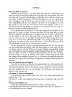
The main model for welding reinforcement using electroslag pressure welding technology
is illustrated in Figure 1.1.
Figure 1.1. Electroslag pressure welding
1.2.2. Current status of electroslag pressure welding research and application
domestically and internationally
a. In Vietnam:
The National Research Institute of Mechanical Engineering (Ministry of Industry and Trade)
chaired a scientific research project at the Department of Science and Technology of Hanoi (Code
TC-CN / 01-08-2) on the application of electroslag pressure welding for steel connection with
positive results. However, due to the limitation of researching scope and funding, the in-depth
scientific issues of this technology have not been studied thoroughly and systematically.
b. In other countries:
China has produced manual equipments and jig to apply electroslag pressure welding at the
construction site. The welding process and welding parameters have been given depending on each
type of reinforcement diameter from 16-32mm. The application of this welding process has been
4
allowed by the Chinese government and is regulated in the construction industry standard JGJ182003, JGJ107-2003.
However, in practical production, welding quality management is very difficult. The quality
of welds is unstable and there are many defects such as lack of penetration, slag inclusion, cracking
of welds, etc. In particular, welds have a disproportionate shape, or are sagging on one side, irregular
size, as well as unable to control the size. Therefore, they are often much larger than required, which
greatly affect the economic efficiency of the project.
1.2.3. Limitations, issues and research orientation
The shape of welds is not unified, many cases are eccentric or sagging. The size of the weld
is often larger than the standard (Δdh > 4mm). This leads to waste of materials, energy, and
welding time.
The weld is cracked
Lack of penetration, slag and air inclusion.
Welding jigs are operated manually, so the setting of welding parameters is not accurate and
depends on the skill of the workers.
The adjustment range in the welding mode table is too wide, the optimal domain of welding
parameters (Ih, Th) has not been determined.
There has been no research on the effect of welding pressure on the quality and shape of
welds. Welding pressure can not be automatically controlled, it relies entirely on the
performance of workers.
Thus, from the general research on the practical situation of reinforcement connecting
methods presented above, it is necessary to find out technology solutions that overcome these
limitations. That leads to the selection of some welding technology parameters that have a strong
influence on weld formation and weld quality through in-depth experiments. In particular, the
welding pressure parameters need to be studied quantitatively to assess its effect on the output
function of this thesis.
CONCLUSION OF CHAPTER 1
Through the study of references and general assessment of the research situation, the
application of reinforcement connecting methods has the following conclusions:
1. Electroslag Pressuer Welding is an advanced welding process that has many outstanding
advantages compared to traditional joining methods, ensuring good quality of welding connection
joints, high load capacity of construction structures, reasonable construction costs. Moreover, it
ensures the increasingly advanced technical requirements of important construction projects at home
and abroad.
2. In Vietnam and China, there have been initial researches and applications of electroslag
pressure welding technology in construction projects which archived some positive results.
However, there are still many limitations and problems that need to be solved, especially the welding
quality is not stable, the welding parameters have not been selected the most suitable, and the
welding equipment has not been automated. Therefore, this issue should be further studied in order
to have a scientific basis for mastery and practical application in important construction works,
contributing to improving the quality and economic efficiency of construction.
5
CHAPTER 2
THEORETICAL BASIS OF ELECTROSLAG WELDING AND ELECTROSLAG
PRESSURE WELDING
2.1. Theoretical basis of electroslag welding
2.1.1. Basic principle of electroslag welding technology
Figure 2.1. Diagram of the electroslag welding in vertical position [26]
2.1.2. Basic technological stages of electroslag welding
2.1.2.1. Preparation of the joint.
2.1.2.2. Positioning of the joint.
2.1.2.3. Connecting electrodes with welded steel
2.1.2.4. Finishing the welding process
2.1.2.5. Checking of the welds
2.1.3. Application, advantages and disadvantages of electroslag welding process.
2.2. Theoretical basis of electroslag pressure welding
2.2.1. Basic principle of electroslag pressure welding technology
Electroslag pressure welding is also based on the basic principle of electroslag welding
process. The welding process also uses arc between two ends of reinforcing steel to melt flux to
create slag pool. Hot slag pool have a high temperature around 19250C [26], higher than the
melting temperature of construction steel at 11470C, will melt the ends of welded steel. However,
it is difficult to supply additional metal in to slag pool and thus inconvenient to manipulate the
construction site. Therefore, to form welds, it is necessary to move and squeeze the two ends of the
molten steels.
The main model for welding reinforcement with electroslag pressure welding technology is
illustrated as follows (Figure 2.2):
Figure 2.2. Electroslag pressure welding model 7
6
The two reinforcing bars should be positioned directly and head-to-head by the upper and
lower clamps of a welding jig.
The welding jig is specially designed to be able to adjust the distance between two steel
rods and create pressure at the end of the welding process. The steel bars are connected to the
welding machine by welding clamps. Surroundings of the joint are covered with welding flux.
2.2.2 Basic technological stages of electroslag pressure welding process
1. Preparation of the joint
4. Elegtroslag process
2. Arc Creating
3. Slag pool creating
5. Creating pressure to form welds
Hình 2.3. Basic technological stages of electroslag pressure welding
2.2.3. Application, advantages and disadvantages of electroslag pressure welding
2.2.3.1. Application
Electroslag pressure welding often used to weld reinforcement in vertical or near vertical
position in the inclined range from 100-150.
It is also possible to weld at a larger inclined range to 450, however special welding jig and
welding parameters are required.
It is often used to weld construction steel or low alloy steel with a diameter range of 14 36mm.
7
2.2.3.2. Advantages of electroslag pressure welding process
- Welding equipment is compact and convenient for operation at the construction site, in
tight spaces.
- It is possible to weld various types of reinforcement with different cross-section shapes:
round, oval, square, rectangular…, or connect different sized reinforcement.
- Short preparation and operation times lead to an increase in productivity, which can be
used to combine several welding jigs with the same welding machine.
- Pressure is not too strong compared to resistant welding, so the jigs are compact and
cheap.
- The welding current is low, so the welding transformer is small, easy to manufacture and
much cheaper than resistant welding.
- High quality welding (due to being protected in the melted slag pool and welds are
formed under welding pressure), no pitting, no slag inclution. Weld metals are similar to base
metals because there are no additional metals.
- Reinforcement is welded concentricly, so tensile, compression resistance, bending
resistance of steel can be increased.
- No pollution: no smoke, no arc, and no noise.
- Save steel in comparison with other reinforcement connecting methods.
2.2.3.3. Disadvantages of electroslag pressure welding process
- Require technical staff and workers with more professional operating skills than other
common welding methods.
- Only weld steel in vertical position or small inclination.
- Do not weld high alloy steel.
- The quality and size of welds significantly depends on the skill of the operator.
2.3. Typical parameters have a strong influence on the shape and quality of electroslag
pressure welding.
2.3.1 Typical parameter of weld quality
When using reinforcement, one of the mandatory requirements is to check the reinforcement
properties. In which, tensile strength is a basic parameter to evaluate the mechanical properties and
quality of reinforcement.
For Elegtroslag pressure welding, after each goup of weld, three weld joints must be taken to
test the tensile strength. If there is a test piece with a tensile value lower than the permissible
durable limit of welded reinforcement, then the number of samples should be doubled to carry out
the re-examination.
Thus, it is imperative to check the tensile strength and their importance to welds, we choose
the objective function to evaluate weld quality Y1 as the tensile strength of the weld k.
2.3.2. Typical parameter of weld shape
Looking at the cross section of the weld, we figured hat the height of weld cladding (dh) is
an important parameter for the following reasons :
This is a parameter specified in the construction standard dh >4m [8];
Increasing adhesion between reinforcement and concrete.
The cross section of the weld increases resulting in increased loading capacity of the
weld;
All defects are pushed out in order to ensure the cross section within the diameter of the
steel bar has no defect.
Thus, the height of weld cladding (dh) is an incredibly important parameter not only for the
shape but also for the weld quality. Therefore, we choose the Y3 target function as the height of
weld cladding (dh).
8
Figure 2.4. Weld cross section of electroslag pressure welding
2.4. The main parameters affect the shape and quality of electroslag pressure welds and
select the input research parameters.
2.4.1. Welding voltage Uh
We realize that the change of welding voltage during welding for different welds and
different reinforcement diameters is very small. The welding voltage is default value and should
not be adjusted to ensure the stability of the welding process. Thus, for electroslag welding, it is
often used with the "Constant-Vontage" welding device.
Therefore, welding voltage is an important parameter for the welding process, but it should be
kept stable throughout the welding process. Consequently, the welding voltage is not the input
parameter while experimentally studying the process of electroslag pressure welding.
2.4.2. Welding current Ih
The method of calculating electroslag welding parameters based on the thermal equilibrium
equation of slag pool in the form of: [1]
qx = qh + qt + qm
In which:
qx - Heat capacity of slag pool, cal/gy;
qh - Heat capacity of base metal melting, cal/gy;
qt - Heat capacity of welding flux melting, cal/gy;
qm - Heat exhaust of slag pool surface, cal/gy.
The total heat of the electroslag welding process is determined according to the following
equation:
n
q x = 0,24
U I
i i
i 1
Electric welding slag has only 1 electrode so n = 1
Looking at the calculation method for the heat output of the slag welding process, we
found out that along with the welding voltage, the welding current also plays essential role in
creating the heat sources to melt fluxs and base metals.
As for the general electroslag welding and electroslag pressure welding in particular,
welds are formed by the amount of melted metal in molten pool. Therefore, the increase in electric
current always leads to increased depth of the melted metals, this leads to an increase in the height
of the weld cladding. However, the change in the height of weld cladding with the welding current
is complicated, the initial increase in the current increases the size, then decreases the size because
the depth of the melted metal is too deep, it will sag the weld. The main effect of increasing
welding current will reduce shape parameters and reduce weld cracking resistance. However, if the
welding current is too low, it will be difficult to create slag pools, which is not enough melted
9
metal to form welds. Thus, the welding current is an important parameter by which it is possible to
change the depth of the melted metal and the shape of the weld.
Welding current also has a great influence on the grain size and heat affects zone size,
directly affecting the mechanical properties of the weld.
Therefore, the welding current is a parameter that directly affects the shape and quality
of the weld, this is a parameter that can be changed to create the desired weld. Therefore, the
welding current is a factor that greatly affects the weld and needs to be carefully studied during
experimental research.
2.4.3. Welding time Th
Welding time (Th ) is the sum of the time of forming the slag pool (Tbx), and the time for
the electroslag Tđx to form the weld.
Th = Tbx + Tđx (s)
The Tbx will determine the depth of the slag pool. It is necessary to limit the minimum
depth of slag pools so that the steel bar can fully submerge into the slag pool and melt the surface
of the steel bar. If the depth of the slag pool is too shallow, it will lead to slag erupting and arcing
on the surface of slag pool, the depth of the melted metal will also decrease. If the slag pool is too
deep, it will increase the heat transfer into the steel bar, reduce the overall temperature of the slag
pool, reduce the circulation of slag, it an be hardened on the surface of the steel bar and cause slag
inclusion of the weld. Therefore, it is necessary to control the time to form slag pools with depths
from 25mm - 50mm [26].
The time of electroslag is the decisive factor to the depth of the melting metal, the size
and shape of the weld. The time of electroslag must be suitable with a ufficient amount of melting
metal to form welds and push defects such as pitting out of the weld. Usually the electroslag time
depends on the size of the steel diameter and in the range of 16s - 50s [7].
Through the analysis process, we acknowledged that the welding time needs to be
changed to suit each type of steel diameter, which clearly affects the shape, size and quality of the
weld. Therefore, they are also parameters to be studied quantitatively when studying experimental
planning
2.4.4. Welding pressure Ph
In the process of electroslag pressure welding to connect reinforcement, we do not use
added metal. Therefore, to form welds it is necessary to move and squeeze the two ends of the
welded steel together.
The force will depend on the steel diameter and is calculated as follows:
F = Ph x S
Trong đó:
F: Force between 2 steel bars (N)
Ph : Welding pressure (MPa)
S : Area of cross section of steel bars (mm2)
Welding pressure is the decisive parameter for weld formation. It not only works to push
all defects and excess metal from the cross section of the weld but also creates a plastic
deformation zone between the two ends of the welded steel bars to increase the bonding capacity
and increase the mechanical properties of the weld. If the welding pressure is not enough, it will
lead to the weld does not completely penetrate the cross section, with internal defects such as
porosity; slag inclusion also leads to reduce weld mechanical properties.
So far, there is no study in on the influence of welding pressure of the size and quality of
electroslag pressure welding. Therefore, this is an important parameter that needs intensive
research when operating experimental planning.
2.4.5. Other parameters
2.4.6. Selecting input parameters
10
As analyzed in the previous sections, we have found that there are 4 technological
parameters that have the greatest impact on weld shape and quality. However, the welding voltage
is a constant parameter to stabilize the welding process. Therefore, the 3 parameters that their
changes have greatly affect the shape and quality of welds are as follows:
Welding current Ih
Welding time Th
Welding pressure Ph
These are the 3 input parameters selected for the experimental planning study to figured out
the relationship between them as well as the output objective function is the tensile strength of
weld Y1 = K and height of weld cladding Y3 = dh.
CONCLUSION OF CHAPTER 2
1. Electroslag pressure welding process to connect construction reinforcement is a new
development of electroslag welding technology with the use of pressure between two steel bars to
replace filling metal. The creation of pressure on the weld at the end of the electroslag pressure
welding process creates plastic deformation zones at both ends of welded steel bars, which further
contributes to the improvement of the quality and reliability of the weld.
2. Electroslag Welding in general and electroslag pressure welding in particular are
welding processes suitable for welding construction steel and low alloy steel. This welding process
results in good quality welds, high productivity and low cost, with compact equipment that is
suitable for application at production sites.
3. The determination of the main welding mode parameters includes: welding current (Ih,
A); welding time (Th, s) ; welding pressure (Ph, MPa) has the greatest impact on weld strength (K,
MPa) and weld shape size (dh, mm) as the scientific basis for building the objective functions
and the input parameters of the experimental planning process.
11
CHAPTER 3
MATERIALS, EQUIPMENTS AND RESEARCH METHODS
3.1. Experimental materials
3.1.1. Welded steel material
Table 3.1. Chemical composition of steel used for experiments by manufacturers [2]:
Steel
grade
CB300-V
CB400-V
C
−
0,29
CB500-V
0,32
Chemical composition (%)
Mn
P
−
0,05
1,8
0,04
0,55
1,8
0,04
Si
−
0,55
S
0,05
0,04
0,04
3.1.2. Welding flux
Table 3.2. Chemical composition of welding flux for experiments:
Chemical composition (%)
flux
HJ431
SiO 2
MnO
FeO
Al 2 O 3
CaF 2
CaO
MgO
S
P
Tạp
chất
42,78
34,26
1,49
4,0
5,04
3,12
5,88
0,012
0,018
0,1
3.2. Equipment for experiments
Figure 3.1. Principle structure of electroslag pressure welding equipment for experiment:
1. Welding machine; 2. Welding jig; 3. Control cabinet
3.2.1. Welding machine
3.2.2. Welding jig
Table 3.3. Conversion table of welding pressure and moment of coupling
25
Welding
pressure Ph
(MPa)
2.5
25
4.5
2.205
442
58
25
6.5
3.185
638
83
Welded steel
diameter (mm)
Axial force F (N)
Moment
(Nmm)
Capacity (W)
1.225
245
32
12
3.2.3. Control device for electroslag pressure welding
Figure 3.2. Electrical control diagram of slag welding machine
3.3. Process of electroslag pressure welding to connect reinforcement in the laboratory
3.3.1. Preparation of samples and laboratory equipments
3.3.2. Weld positioning
3.3.3. Electroslag pressure welding process
3.3.4. Processing of samples
a)
c)
b)
Figure 3.3. Photos of some experiments to measure geometrical dimensions, determine
tensile strength
a) Tensile test samples; b) Sides of samples; c) Top surfaces of the samples
13
3.4. Equipments and methods for checking the weld quality of electroslag pressure welding
3.4.1. Mechanical properties testing equipment for welds
3.4.2. Measurement equipment for weld dimensions
3.4.3. Equipments for checking of the material structure at the weld and heat-affected zone
3.5. Conditions and methods for implementing experimental planning
3.5.1. Experimental conditions according to orthogonal planning
3.5.2. Experimental methods
Table 3.4. Coding of 3 parameters of electroslag pressure welding technology (experimental
matrix) according to experimental planning of type N = 33 = 27
Survey elements
X 3 (level 0)
X 3 (level 1)
X 3 (level 2)
X 2 (level 0)
X 2 (level 1)
X 2 (level 2)
X 1 (level 0)
000
010
020
X 1 (level 1)
100
110
120
X 1 (level 2)
200
210
220
X 1 (level 0)
001
011
021
X 1 (level 1)
101
111
121
X 1 (level 2)
201
211
221
X 1 (level 0)
002
012
022
X 1 (level 1)
102
112
122
X 1 (level 2)
202
212
222
Method of calculating objective functions
a. Welding tensile strength
Tensile strength of welds (K, MPa) is the most important parameter of electroslag pressure
welding. It is determined by the following formula:
P
4P
(3.3)
K Y1
S .d t2.b
In which:
K - Welding tensile strength, MPa;
Y1 - The first objective function;
P - Traction force value at the time of specimen destruction, N;
S – The weld cross-sectional area of the test piece, mm2;
d t.b - Average diameter of welded reinforcement, mm;
Due to the fact that welded steel has an uneven diameter, on the other hand, the weld
diameter is enlarged so that when pulling, it usually doesn't break at weld. Therefore, to accurately
determine the diameter size as well as measure the tensile strength at the weld, we proceed to
small diameter of the reinforcement diameter at the weld joint area so that the test diameter is
smaller than the nominal diameter of welded steel bars.
b. The height of weld cladding (dh)
The height of weld cladding (dh) is a vital parameter to evaluate weld properties. It
does not only demonstrate the load capacity, but also evaluates the economic efficiency of the
welding method. The height of weld cladding is an objective function that needed to be found,
calculated according to the following formula:
14
n
(d
d h Y3
i
d d .n )
i 1
2n
(3.4)
In which:
dh - The average height of weld cladding, mm;
Y3 - The second objective function;
di - The value measures the diameter of the weld at conventional points, mm;
dd.n - Nominal diameter of welded steel bars, mm;
i - The serial number of the measurements at the corresponding measurement positions, i =
1, 2, 3, 4, 5, 6... ;
n - Number of measurement positions.
In the experiment, measurements were taken at 6 locations separated by 300, then take
calculate their average values.
CONCLUSION OF CHAPTER 3
1. Tested equipment is highly accurate and reliable. The selected welding steel CB400-V
with diameter D = 25mm is widely used in high-bulding constructions in Vietnam. HJ431 welding
flux is also chosen as a popular flux in the market and has a reasonable price.
2. Researched, designed and manufactured automatic welding jig using servo motor with
moment clutch, integrated with PLC control module. The welding jig ensures fast and precise
reversal of movement to facilitate the control the journey and the up-down movement speed of
welding reinforcement, accurately setting welding time and welding pressure within the survey
domain expected according to experimental planning with high reliability.
3. Selected main parameters to study include: Ih, Th and Ph với dd.n=25mm. The output
objective function for evaluating the quality and shape of welds is the weld tensile strength (K,
MPa) and The height of weld cladding dh, mm). The experimental matrix is determined according
to the 3-level experimental model of 3 inputs N27 (the total number of experiments is N = 33 = 27)
with the limit of their survey domain based on the results of theoretical research and some
technology-oriented experiments in Vietnam.
15
CHAPTER 4
RESEARCH EFFECTS OF THE WELDING PARAMETERS TO THE
CHARACTERISTICS OF THE WELDS OF ELECTROSLAG PRESSURE WELDING
4.1. Selecting adjustment domain of welding parameters according to experimental plan N27.
4.1.1. Selecting adjustment domain of welding current Ih (X1)
Survey level selected X1: Level 0: 300A, Level 1: 450A, Level 2: 600A.
Adjustment step 1= 150A.
4.1.2. Selecting adjustment domain of welding time Th (X2)
Survey level selected X2: Level 0: 25s, Level 1: 30s, Level: 35s.
Adjustment step 2 = 5s.
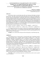
4.1.3. Survey selection of adjustable domain of welding pressure Ph (X3)
Table 4.1. Experimental results of the effect of welding pressure (Ph) to weld tensile strength:
Mechanical properties of
welds
Tensile strength, K,
MPa
1,5
2,5
399
562
welding pressure Ph (MPa)
3,5
4,5
5,5
613
625
637
6,5
7,5
645
650
Figure 4.1. The effect of welding pressure on the tensile strength of electroslag pressure
welding in welding parameters: Ih = 400 5,0 A; Th = 25 0,05 s và dd.n = 25 mm
Survey level selected X3: Level 0: 2,5MPa, Level 1: 4,5MPa, Level 2: 6,5 MPa.
Adjustment step 3 = 2,0 MPa.
Table 4.2. Experimental conditions for adjusting technology according to
experimental planning N27:
Welding parameters
Adjustment step,
Level
Level
Level
Symbol
0
1
2
i
Welding current Ih, (A)
Welding time Th, (s)
Welding pressure Ph, (MPa)
X1
X2
X3
300
25,0
2,5
450
30,0
4,5
16
600
35,0
6,5
150,0
5,0
2,0
4.2. Results of experimental research on electroslag pressure welding.
4.2.1. Effect of welding parameters on tensile strength of electroslag pressure welding
Welding test of welded steel samples with nominal diameter D25mm according to welding
parameters as shown in Table 4.2.
Pictures of experimental samples are shown in Figure 4.2
Figure 4.2. Sample of testing of weld tensile strength
Table 4.3. Measurement results and calculation of tensile strength of electroslag pressure
welding on the experimental planning sample N27
Number of
experiments
Welding parameters
Code
1
2
Experimental lot 1
01
000
02
010
03
020
04
100
05
110
06
120
07
200
08
210
09
220
Experimental lot 2
10
001
11
010
12
021
13
101
14
111
15
121
16
201
17
211
18
221
Experimental lot 3
19
002
I h (A)
3
Size (mm) Force (N)
T h (s) P h (MPa)
4
5
6
Tensile strength
(N/mm2 )
7
8
300
300
300
450
450
450
600
600
600
25
30
35
25
30
35
25
30
35
2,5
2,5
2,5
2,5
2,5
2,5
2,5
2,5
2,5
15,0
15,0
14,8
14,9
14,9
15,0
14,9
14,9
15,0
52745
63818
59483
66388
79061
76541
79730
91938
90765
298
361
346
381
453
433
457
527
514
300
300
300
450
450
450
600
600
600
25
30
35
25
30
35
25
30
35
4,5
4,5
4,5
4,5
4,5
4,5
4,5
4,5
4,5
15,0
15,0
14,8
14,9
14,9
15,0
14,9
14,9
15,0
86907
93710
90386
96647
101239
99953
102489
109581
108376
492
530
525
554
581
566
588
628
613
300
25
6,5
15,0 103399
585
17
20
21
22
23
24
25
26
27
012
022
102
112
122
202
212
222
300
300
450
450
450
600
600
600
30
35
25
30
35
25
30
35
6,5
6,5
6,5
6,5
6,5
6,5
6,5
6,5
15,0
14,8
14,9
14,9
15,0
14,9
14,9
15,0
110143
105379
106744
112110
111704
110889
117255
115591
623
613
612
643
632
636
672
654
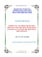
4.2.1.1. Tensile strength of welds k = f(Th, Ih)at 3 different Ph levels
a)
b)
Figure 4.3. Graph of simultaneous effects of
welding time (Th) and welding current (Ih) on
tensile strength of electroslag weld (K) at
different welding pressure levels:
a)Ph = 2,5MPa; b) Ph= 4,5MPa;
c) Ph= 6,5 MPa.
c)
4.2.1.2. Tensile strength of welds K = f(Ph, Ih)at 3 different Th levels
a)
b)
Figure 4.4. Graph of simultaneous effects of
welding pressure (Ph) and welding current
(Ih) on tensile strength of electroslag weld
(K) at different welding time levels:
a) Th = 25 s; b) Th = 30 s; c) Th = 35 s
c)
18
4.2.1.3. Tensile strength of welds K = f(Ph, Th)at 3 different Ih levels
a)
b)
Figure 4.5. Graph of simultaneous effects of
welding pressure (Ph) and welding time (Th)
on tensile strength of electroslag weld (K)
at different welding current levels:
a) I h = 300A; b) I h = 450A;
c) I h = 600A
c)
4.2.1.4. Mathematical modeling of the effect of welding parameters on weld tensile
strength K = f(Ih, T h , P h) .
For a general view of the effect of 3 technological parameters of electroslag pressure
welding on the output function, use STATISTICA software to provide graphs in 3D space and
mathematical formulas. Thereby, the simultaneous influence of two main parameters including
welding current (Ih) and welding time (Th) at 3 fixed levels of welding pressure parameters
(Ph) can be seen clearly.
a)
b)
Figure 4.6. Tensile strength of electroslag
pressure weld Y1 = K = f(Ih, Th) at welding
pressure levels: Ph = 2,5 MPa (a); Ph = 4,5
MPa (b) và Ph = 6,5 MPa (c)
c)
19
The mathematical equations received corresponds to the 3D graph in Figure 4.6 as bellow:
At welding pressure level Ph = 2,5 MPa:
Y1= 1482,93481+ 0,6611.Ih+105,5694.Th0,0002. I
+ 0,0031.Ih.Th 1,6956.T 2
2
h
(4.1)
h
At welding pressure level Ph = 4,5 MPa:
Y1 = 541,8156 +0,5507.Ih + 59,6278.Th + 0,0002. I 2 0,0027.Ih.Th 0,9344.T
h
2
h
(4.2)
At welding pressure level Ph = 6,5 MPa:
Y1 = 388,1919 + 0,1861.Ih + 61,5462.Th + 6,9383. I 2 0,0031.Ih.Th 0,9622. T 2
h
h
(4.3)
To ensure the tensile strength of reinforcement, the function Y1 must satisfy:
Y1 ≥ 570MPa [3]
4.2.1.5. Optimal welding parameters selection with the priority of weld tensile strength
K = f(Ih, Th, Ph)
Thus, when surveying with the output target function is the tensile strength of the weld, we select
the optimal range of parameters in the survey domain of the input elements as follows:
Ph = 4,5 - 6,5MPa
Ih = 430 - 450 A
Th = 28 - 32 s
4.2.2. Effect of welding parameters on weld size of electroslag pressure welding
In Table 4.4, the results of measuring and calculating the average diameter (dtb) and the
height of weld cladding (dh) of the electroslag pressure weld are obtained according to the
experimental plan of type N27 with steel bar type ddn = 25 mm, CB400-V steel grade.
Table 4.4. Measurement results and calculation of average diameter and the height of weld
cladding (dh) of electroslag pressure welding on the experimental planning sample N27
N0
Welding
parameters
Code
Ih
(A)
1
2
3
Experimental lot
01 000 300
02 010 300
03 020 300
04 100 450
05 110 450
06 120 450
07 200 600
08 210 600
09 220 600
Th
Ph
(s) (MPa)
4
1
25
30
35
25
30
35
25
30
35
Position measurement of weld
diameter according to
cross section (0 )
0
30
60
90
120
150
5
6
7
8
9
10
11
2,5
2,5
2,5
2,5
2,5
2,5
2,5
2,5
2,5
31,5
34,5
32,5
34,0
36,5
35,0
35,0
38,5
38,0
31,5
34,5
33,0
34,0
37,0
35,0
35,0
38,5
38,0
31,0
35,0
33,5
33,5
37,5
35,5
36,0
39,5
38,5
31,0
34,5
33,0
33,0
37,0
35,5
36,0
39,5
38,5
31,5 31,0
35,0 ,35,0
33,0 , 33,5
34,0 , 33,5
37,0 37,5
35,0 35,5
35,5 36,0
39,0 39,5
38,0 38,5
20
Average
diameter the height
of weld
of weld
cladding
dt.b
dh, mm
mm
12
31,2500
34,7500
33,0833
33,7500
37,0833
35,2500
35,5833
39,0833
38,2500
13
3,1250
4,8750
4,4041
4,3750
6,0416
5,1250
5,2916
7,0416
6,6250
Experimental lot
10 001 300
11 011 300
12 021 300
13 101 450
14 111 450
15 121 450
16 201 600
17 211 600
18 221 600
Experimental lot
19 002 300
20 012 300
21 022 300
22 102 450
23 112 450
24 122 450
25 202 600
26 212 600
27 222 600
2
25
30
35
25
30
35
25
30
35
3
25
30
35
25
30
35
25
30
35
4,5
4,5
4,5
4,5
4,5
4,5
4,5
4,5
4,5
33,5
39,0
36,5
37,5
42,0
40,0
40,0
45,0
44,0
34,0
39,0
37,0
37,5
42,5
40,5
40,5
45,5
44,5
34,5
39,0
37,5
38,0
42,5
40,5
41,0
45,5
44,0
34,5
38,5
37,5
38,0
42,5
40,5
41,0
46,0
43,5
34,5
38,5
37,5
38,0
42,5
40,0
40,5
45,0
43,5
34,0
38,5
37,0
37,0
42,0
39,5
40,0
45,0
43,5
34,1666
38,7500
37,1666
37,6666
42,3333
40,1666
40,5000
45,3333
43,8333
4,5833
6,8750
6,0833
6,3333
8,6666
7,5833
7,7500
10,1666
9,4166
6,5
6,5
6,5
6,5
6,5
6,5
6,5
6,5
6,5
35,5
41,0
39,0
39,0
43,5
42,5
41,0
46,0
44,0
35,5
40,5
39,5
39,0
43,5
42,0
41,0
46,5
44,0
36,0
40,0
39,5
38,5
43,5
42,0
41,5
47,0
44,5
36,0
40,0
39,0
38,5
44,0
42,0
41,5
46,5
44,5
36,0
40,5
39,0
38,0
44,0
42,5
41,5
46,5
44,5
35,0
41,0
39,0
38,0
43,5
42,5
41,5
46,5
44,5
35,6666
40,5000
39,1666
38,5000
43,6666
42,2500
41,3333
46,5000
44,3333
5,3333
7,7500
7,0833
6,7500
9,3333
8,6250
8,1666
10,7500
9,6666
4.2.2.1. The height of weld cladding Δdh = f(Th, Ih) at 3 different Ph levels
b)
a)
Figure 4.7. Graph of simultaneous effects of
welding time (Th) and welding current (Ih)
on the height of weld cladding dh at
different welding pressure levels:
a)Ph = 2,5MPa;
b) Ph= 4,5MPa;
c) Ph= 6,5 MPa.
c)
21
4.2.2.2. The height of weld cladding Δdh = f(P h , I h) at 3 different T h levels
b)
a)
Figure 4.8. Graph of simultaneous effects of
welding pressure (Ph) and welding current
(Ih) on the height of weld cladding dh at
different welding time levels:
a) Th= 25 s; b) Th= 30 s; c) Th = 35 s
c)
4.2.2.3. The height of weld cladding Δd h = f(P h,T h) at 3 different Ih levels.
a)
b)
Figure 4.9. Graph of simultaneous effects of
welding pressure (Ph) and welding time (Th)
on the height of weld cladding dh at different
welding curent levels: a) I h= 300A;
b)I h=450A; c) I h = 600A
c)
4.2.2.4. Mathematical modeling of the effect of welding parameters on the height of
weld cladding dh = f(Ih, Th, Ph).
Using STATISTICA software to process the data in Table 4.4 to produce graphs in 3dimensional space (3D) and mathematical expressions showing the simultaneous influence of two
main parameters including welding current (Ih = 300 600 A) and welding time (Th = 25 - 35 s)
at three fixed levels of welding pressure (Ph = 4,5 MPa and Ph = 6,5 MPa) to the output target
function is the height of weld cladding Y3 = Δdh (mm).
22
a)
b)
Figure 4.10. The height of weld cladding
Y3 = dh= f(Ih, Th) at welding pressure
levels: Ph = 2,5 MPa (a); Ph = 4,5 MPa (b)
và Ph = 6,5 MPa (c)
c)
The mathematical equations received corresponds to the 3D graph in Figure 4.10 as bellow:
At welding pressure level Ph = 2,5 MPa:
Y3 = 41,8466 + 0,0049.Ih + 2,8923.Th + 2,0679.106. I h2 + 1,8063.105.Ih.Th 0,0465.T
2
h
(4.4)
At welding pressure level Ph = 4,5 MPa :
Y3 = 58,8466 + 0,0112.Ih + 3,9889.Th 2,1604.106. I 2 + 5,5553.105.Ih.Th 0,0644. T
h
2
h
(4.5)
At welding pressure level Ph = 6,5 MPa:
Y3 = 62,3566 + 0,0163.Ih + 4,225.Th 4,9384.106. I 2 8,3333.105.Ih.Th 0,0669. T 2
h
h
(4.6)
The value of Y3 function is defined as Y3 >4mm [8]
In order to ensure technical requirements as well as economic efficiency, we choose the
height of weld cladding in the following range of values:
5mm ≤ Y3 ≤ 8mm
4.2.2.5. Select the optimal electroslag pressure welding parameters with the
priority of the height of weld cladding dh = f(I h, T h, P h ) .
Thus, when surveying with the output target function is the height of weld cladding, we
select the optimal range of parameters in the survey domain of the input elements as follows:
Ph = 4,5 - 6,5 MPa
Ih = 400 - 450 A
Th = 25 - 30 s
4.3. Select the optimal welding parameters in the survey domain to ensure that the
objective functions are weld size and weld quality.
The influence of the main technological parameters surveyed according to the experimental
plan N27 to the target output functions to be found is shown in 2D, 3D graphs and mathematical
equations.
After analyzing with each specific objective function, appropriate values have been
selected in each case. However, the parameter ranges are different. Therefore, it is necessary to
23