Tài liệu đào tạo dành cho kỷ sư trong hệ thống năng lượng mặt trời.
Bạn đang xem bản rút gọn của tài liệu. Xem và tải ngay bản đầy đủ của tài liệu tại đây (5.14 MB, 259 trang )
Seediscussions,stats,andauthorprofilesforthispublicationat: />
TrainingManualforEngineersonSolarPV
System
TECHNICALREPORT·JULY2011
DOI:10.13140/2.1.3156.9607
2AUTHORS,INCLUDING:
ShreeRajShakya
TribhuvanUniversity
17PUBLICATIONS30CITATIONS
SEEPROFILE
Availablefrom:ShreeRajShakya
Retrievedon:23August2015
ALTERNATIVE ENERGY PROMOTION CENTRE
(AEPC)
ENERGY SECTOR ASSISTANCE PROGRAMME
(ESAP)
Training Manual For Engineers on
Solar PV System
July 2011
Government of Nepal
Ministry of Environment, Science and Technology
Alternative Energy Promotion Center (AEPC)
Energy Sector Assistance Programme (ESAP)
Khumaltar Height, Lalitpur
P.O. Box: 14237, Kathmandu, Nepal
Tel: +977-1-5539390, 5543044, 5539391. Fax: +977-1-5539392
Email:
Web site: www.aepcnepal.org
Coordinated by
Ram Prasad Dhital, Sr. Energy Officer
Madhusudhan Adhikari, Solar Energy Component Manager
Team of authors
Prof. Dinesh Kumar Sharma, Dr.
Team leader and PV Expert
Er. Shree Raj Shakya,
Energy Expert
Editing Team:
Mr. Mukesh Ghimire
Mr. Chaitanya P Chaudhary
Energy Officer AEPC
Program Officer AEPC/ESAP
Preface
The Alternative Energy Promotion Centre (AEPC) was established in 1996 as an apex
government body to promote the use of renewable energy technologies to meet
energy needs in rural areas of Nepal. With successful completion of the first phase of
the Energy Sector Assistance Programme (ESAP), AEPC has initiated second phase
of the programme from March 2007 with support from Government of Denmark and
the Government of Norway. The support to solar energy is one among the different
programme components.
Working for promotion of the PV technology among the rural population out of
access to electricity, ESAP has been carrying out different trainings for capacity
building of partner organizations. As a training tool to use in Solar Design Engineers’
training, a manual has been developed with effort from experts and other concerned.
This volume of Training Manual for Engineers on Solar PV System consist of
technical details required for feasibility study, designing and implementation of
institutional Solar Photovoltaic systems. The manual is with adequate information
and guidelines to be used in training for engineers working in solar PV or with
interest to work in the sector.
Authors’ team of PV expert, Prof. Dr. Dinesh Kumar Sharma and energy expert,
Engineer Shree Raja Shakya has put their significant effort for preparing this manual.
I would like to acknowledge their effort in this endeavour.
I would like to thank SSP manager Mr. Madhusudhan Adhikari and Sr. Energy officer
Ram Pd Dhital for support while preparing this manual and would like to thank
AEPC Energy officer Mr.Mukesh Ghimire, SSP programmer officer Mr. Chaitanya P
Chaudhary for their support in this attempt.
I further would like to acknowledge the support of all responding institution and
individuals who provided the valuable information to complete this manual.
Dr. Narayan Prasad Chaulagain
Executive Director
Alternative Energy Promotion Centre (AEPC)
Table of Contents
Training Manual for Engineers on Solar PV System – At a Glance
Training Schedule
1.
Skill Standards of CTEVT, Skill Testing/ Certification procedures
1
2.
Features and requirements for Skill Standard tests and certification
procedures for solar photovoltaic Design Engineer and Technicians
3
3.
History of development of solar photovoltaic technology in Nepal
5
4.
Basics of Electrical Engineering
4.1
Electrical Power Supply System
4.2
Solar Photovoltaic Technology
11
12
17
5.
Fundamentals of solar photovoltaic technology
5.1
Basic Principles of Photo-Voltaic Effect
5.2
Solar Cells
5.3
Solar Modules
5.4
Solar Array
27
28
33
43
51
6.
Components of a solar photovoltaic system
6.1
Batteries
6.2
Charge Controllers
6.3
Lamps and Other Loads
6.4
DC-AC Inverters
6.5
DC-DC Converters
6.6
Wiring and installation practices
57
58
73
80
86
90
92
7.
Solar home system (SHS) design and installation
7.1
Design of Solar Home System (SHS)
7.2
Installation of Solar Module
7.3
Installation of Charge Controller
7.4
Installation of Battery
7.5
Wiring of the solar home system components
7.6
Lamp installation procedures
7.7
Switch installation procedures
7.8
Power socket installation procedures
7.9
Components assembly of Solar Home System
7.10 Installation of solar home system components
95
97
106
109
110
110
115
117
118
119
123
8.
Repair and maintenance of components of solar photovoltaic systems
8.1
Solar Module
8.2
Battery
8.3
Charge Controller
8.4
Solar Lamp
8.5
DC-AC Inverter
8.6
DC-DC Converter
125
127
127
131
141
144
144
8.7
9.
Demonstration of various components, their testing and repairing
procedures
145
Design aspects of large solar photovoltaic systems
(non-pumping applications)
9.1
Load calculations
9.2
Sizing of Module /Array
9.3
Sizing of Storage Battery
9.4
Sizing of Charge Controller
9.5
Sizing of Wire/ Cable
9.6
Sizing of Inverter
9.7
Sizing of DC-DC Converter
9.8
Installation Procedures, Safety and Protection
149
151
156
159
161
163
165
167
168
10.
Design aspects of water pumping systems
10.1 Introduction
10.2 Water Pumping System Configurations
10.3 Water Pumps
10.4 Motors
10.5 Integrated Pump/Motor Machines
10.6 Power Conditioning Circuitry
10.7 Array Wiring and Mounting of Water Pumps
10.8 Water Pumping System Design
10.9 Installation Line Diagrams
10.10 Routine and Preventive Maintenance
10.11 Monitoring and Evaluation of Installed Water Pumps
189
191
193
194
198
200
203
204
205
214
217
218
11.
Socio – techno Economic Feasibility Study
11.1 Introduction
11.2 Basic Principles of Feasibility Study
11.3 Technical Aspects of Feasibility Study
11.4 Energy Demand Analysis
11.5 Financial Analysis
11.6 Sensitivity Analysis
11.7 Repayment Schedule
11.8 Cash Flow Analysis
11.9 Tables and Formula for Quick Reference
11.10 Suggested Format for Feasibility Study
221
222
222
223
224
224
234
235
236
240
244
References
Technical Glossary
Appendices:
1.
Nepal Interim PV Quality Assurance
2.
Format for Feasibility Study of ISPS
3.
Solar Radiation in Different Parts of Nepal
4.
Technical Catalogues of Various Solar PV Components
Training manual for Engineers on Solar PV System
1.
Objective: To provide training to the Engineers capable of working and
willing to work on Solar Photovoltaic Systems.
2.
Duration: 8 days (49 hours) + 1 day Field Visit
3.
Minimum Qualification of trainee: Bachelor’s degree in Engineering.
4.
Minimum Qualification of trainer: Engineers or PV experts with good
experience in design and installation of Solar Photovoltaic Systems.
5.
Reference materials:
a) Solar Photovoltaic System Design Manual for Solar Design Engineers,
AEPC/ESAP
b) Solar Electricity Technical Training Manual (Level 1), AEPC/ESAP.
c) Solar Electricity Technical Training Manual (Level 2), AEPC/ESAP.
d) Training manual for training of Solar technician trainers
6.
Suggested course outline:
i. Skill standards of CTEVT and skill testing/ certification procedure.
ii. Features requirements of certification procedure for Solar PV Technician
level-1.
iii. Features requirements of certification procedure for Solar PV Technician
level-2.
iv. History and development of solar photovoltaic in Nepal featuring history,
installed capacity, users and promoting institutions, donors, future plans and
programs.
v. Basic of electrical engineering theory.
vi. Components of solar PV systems
a) Solar cell, module, array
b) Storage batteries
c) Charge regulators
d) Inverters and converters
e) Wiring and installation practices
vii. Solar home system (SHS) design and installation
a) Components of SHS
b) Installation norms and practices of SHS
c) Basic design of SHS
viii. Repair and maintenance of components of solar PV systems
a) Modules / arrays
b)
c)
d)
e)
DC ballast
Charge controllers
Batteries
DC converters and inverters
ix. Design aspects of large (institutional) PV systems – non pumping applications
a) Load calculation
b) Sizing of module/ array
c) Sizing of storage battery
d) Sizing of wires and cables
e) Installation procedures/ safety and protection
x. Design aspects of water pumping schemes
f) Load calculation
g) Sizing of module/ array
h) Sizing of storage battery
i) Sizing of wires and cables
j) Installation procedures/ safety and protection
k) Socio-techno economic feasibility study of large solar photovoltaic
systems.
Training Schedule
Session
I
Day 1
1&2
Day 2
5.3 &
5.4
II
3&
Part of
4.1
6.1
III
Part of
4.1, 4.2
& 5.1
6.2
IV
Part of
5.1 &
5.2
6.3 &
6.4
Day 3
Part of
6.5,
6.6 &
7.1
Part of
7.1
Day 4
7.4, 7.5
& 7.6
Day 5
Part of
8.1, 8.2
& 8.3
Day 6
9.1, 9.2
& 9.3
Day 7
10.1,
10.2 &
10.3
7.7, 7.8
& 7.9
Part of
8.3, 8.4
& 8.5
9.4 &
9.5
Part of
7.1
7.10
Part of
8.6 &
8.7
Part of
9.6, 9.7
& 9.8
10.4,
10.5,
10.6 &
10.7
10.8
Part of
7.1, 7.2
& 7.3
7.10
Part of
8.7
Part of
9.8
10.8
Day 8
Part of
11.1 11.4 &
11.5
Part of
11.5
Part of
11.5,
11.6,
11.7 &
11.8
Part of
11.8,
11.9 &
11.10
The duration of each session will be 90 minutes. There will be 15 minutes break
between the sessions.
Field visit should be conducted after the completion of chapter 10.
REFERENCES
1.
2.
3.
4.
5.
6.
7.
8.
9.
10.
11.
12.
13.
14.
15.
16.
17.
Fraunhofer-Institute fur Solar Energiessysteme (FhG-ISE), Photovoltaic
Systems, March, 1995
Solar Photovoltaic System Design Manual for Solar Design Engineers,
Alternative Energy Promotion Center (AEPC)/ Energy Sector Assistance
Programme (ESAP), 2003
Solar Electricity Technical Training Manual (Level 1), Alternative Energy
Promotion Center (AEPC)/ Energy Sector Assistance Programme (ESAP),
2006
Solar Electricity Technical Training Manual (Level 2), Alternative Energy
Promotion Center (AEPC)/ Energy Sector Assistance Programme (ESAP),
2006
Martin A. Green, Solar Cells, The University of New South Wales,
Kensington, Australia, February, 1992
L. Stamenic; G. Ingham, Solar Photovoltaic Revolution, United power
Limited, Canada, 1995
J. Schaeffer et.al. , Solar Living Source Book, Chelsea Green Publishing
Company, Vermont, 1994
J.N.Shrestha, Photovoltaic Technology-Course Manual, Institute of
Engineering, Tribhuvan University, 1999
Training Manual for Solar Electric Technician (Level-2), Alternative
Energy Promotion Center (AEPC)/ Energy Sector Assistance Programme
(ESAP), 2001
Vervaart M.R.; Nieuwenhout F.D.J, Manual for the Design and
Modification of Solar Home System Components, IBRD/ The World
Bank, USA, 2001
Status of Solar Photovoltaic Sector in Nepal, Alternative Energy
Promotion Center (AEPC)/ Energy Sector Assistance Programme (ESAP),
2003
Schaeffer J., Alternative Energy Source Book, 7-th edition, 1992.
Joshi A.R., et.al., Environmental Management and Sustainable
Development at the Crossroad, 2003.
CADEC, 2003. Renewable Energy: Data of Nepal, Community Awareness
Development Center, Kathmandu, Nepal.
Piya R., Study on Quality Interventions, Product Quality and System
Performance of Solar Home System in the Market of Nepal(Case
study of Solar Energy Support Programme (SSP) of AEPC/ESAP),
2006
www.pvpower.com
www.pvresources.com
Chapter 1
Skill Standards, Testing/ Certification Procedures
CHAPTER 1
Skill Standards of CTEVT, Skill Testing/ Certification Procedures
Duration:
90 minutes
Physical Facilities required: Class room with white board and multi-media projection
facility.
Materials required: Brochures of Skill Testing Division (STD) of CTEVT
Procedures:
1. Instructor explains the composition of CTEVT, its aims and objectives.
2. Instructor explains the functions of Skill Testing Division of CTEVT processes
involved in skill certification.
3. Q & A session, Examples
Instructor: Invited guest speaker from CTEVT – STD
Reference:
1. Skill Standards for Solar Technicians Level 1 and Level 2
2. Rules and Regulations of CTEVT – STD
Lesson Plan
SubLesson details
chapter
1
Skill Standards of
CTEVT, Skill
Testing/ Certification
Procedures
Teaching
Methodology
Lecture
1
Facilities
required
Class room
Duration Remarks
90 mins.
Chapter 2
Features and Requirements for Skill Tests and Certification
CHAPTER 2
Features and requirements for Skill Standard Tests and Certification
procedures for solar photovoltaic Design Engineer and Technicians
Duration:
90 minutes
Materials required:
a) Solar Technicians Level 1 and Level 2 Skill Standards
b) CTEVT documents on Skill Certification for Solar PV Technicians Level 1 and
Level 2
c) Solar photovoltaic Design Engineer requirements
Procedures: The instructor/s explain
a) Objective of Solar photovoltaic Design Engineer Certificate
b) Objective of Solar PV Technicians Level 1 and Level 2 Certificate
c) Processes involved in Skill Testing
d) Certification procedures
e) Q & A session
Instructor:
a) Invited guest speaker from CTEVT
b) The Trainer
Reference:
1. Skill Standards for Solar Technicians Level 1 and Level 2
Lesson Plan
SubLesson details
Teaching
chapter
Methodology
2
Features and
Lecture
requirements for Skill
Standard Tests and
Certification
procedures for Solar
photovoltaic Design
Engineer and Solar
Technicians Level 1
and Level 2
3
Facilities
required
Class room
Duration Remarks
90 mins.
Chapter 3
History and development of solar PV technology
CHAPTER 3
History of Development of Solar Photovoltaic in Nepal
Duration:
45 minutes
Physical Facilities required: Class room with white board and multi-media projection
facility.
Materials required: Reference materials
Procedures: The instructor/s
a) explains the development stage of Solar PV in Nepal
b) provides updated statistics of use of Solar PV in Nepal
c) elaborates on the roles/ responsibilities of various agencies involved in the
promotion of solar PV in Nepal (AEPC, ESAP, REP, CTEVT, CRE, CES, KU,
etc.)
Instructor: The Trainer
Reference:
1. Solar Photovoltaic System Design Manual for Solar Design Engineers,
AEPC/ESAP
2. Solar Photovoltaic Data Book, AEPC/ESAP
3. Brochures of various institutes
Lesson Plan
Subchapter
Lesson details
Teaching
Methodology
Facilities
required
Duration
3
History of
development of Solar
cells
Lecture
Class room
45 mins.
5
Remarks
History and development of solar PV technology
Chapter 3
Solar Energy
The energy from the sun can be exploited directly in the form of heat or first converted
into electrical energy and then utilized. Accordingly the solar energy is classified into
solar thermal and solar photovoltaics (PV).
Solar thermal has numerous applications like water heating, drying vegetables and
agricultural products, cooking etc. In Nepal the solar water heaters are being extensively
used in urban areas. The applications of solar dryers and cookers have found moderate
use simply because of the low level of dissemination of these technologies.
The solar PV, on the other hand, is extensively used not only in the developing countries
but also in highly developed countries. The application of solar PV is virtually unlimited.
Countries like Germany, Japan and United States of America have initiated highly
subsidized rooftop programs for solar PV. The level of subsidy is up to 65% of the total
system cost. In Nepal solar PV is extensively used for communications, home lighting,
drinking water pumping etc. The installed capacity of Solar PV in Nepal now exceeds 3.4
MWp mark and over 93,000 households are electrified using this technology.
Considering the positive impact that solar PV can bring to the rural population of the
developing countries like Nepal, the Government of Kingdom of Denmark has supported
Energy Sector Assistance Program (ESAP) to promote alternative energy sources,
including PV. ESAP target was to subsidize installation of 25,000 Solar Home Systems
within a time span of 5 years. Similarly, a sizeable project with assistance from European
Union (EU) is being implemented to promote institutional Solar PV in Nepal.
The solar PV can be considered the only form of electricity that can be generated any
time and anywhere provided sunshine is available. The earth receives more energy from
the sun in just one hour than the world uses in a whole year. The annual total amount of
solar energy incident on the surface of the earth is estimated to be about 795 x 1012 MWh,
which is 8300 times greater than the global energy demand in 1991. The Environmental
savings from the Photovoltaic modules are highlighted in table 3.1 below:
Table 3.1 Environmental Savings from Photovoltaic Modules
Description
Electricity saved per year
Electricity saved per life of PV module
Barrels of oil saved over lifetime of PV module
Pounds of coal saved over lifetime of PV module
Carbon Di-oxide kept out of the air over life of PV
Sulfur Di-oxide kept out of air over life of PV
* Based on:
Coal required to produce 1 kWh = 1 lb
Carbon Di-oxide emission = 1.5 lb/kWh
6
Savings of one 50Wp module *
90 kWh
2700 kWh
4.8 barrels
2700 lbs
4000 lbs
23.3 lbs
Chapter 3
History and development of solar PV technology
Photovoltaic (PV) Technology
Photovoltaic (PV) Technology is a process of generating electrical energy from the
energy of solar radiation. The principle of conversion of solar energy into electrical
energy is based on the effect called photovoltaic effect. The smallest part of the device
that converts solar energy into electrical energy is called solar cell. Solar cells are in fact
large area semiconductor diodes, which are made by combining silicon material with
different impurities. The sand, a base material for semiconductor, is the most abundantly
available raw material in the world. The ordinary sand (SiO2) is the raw form of silicone.
The solar energy can be considered as a bunch of light particles called photons. At
incidence of photon stream onto solar cell the electrons are released and become free. The
newly freed electrons with higher energy level become source of electrical energy. Once
these electrons pass through the load, they release the additional energy gained during
collision and fall into their original atomic position ready for next cycle of electricity
generation. This process of releasing free electrons (generation) and then falling into
original atomic position (recombination) is a continuous process as long as there is the
stream of photons (solar energy) falling onto the solar cell surface.
History of Development of PV Technology
The birth of PV technology dates back to 1839 AD when Edmund Becquerel, the French
experimental physicist, discovered the photovoltaic effect while experimenting with an
electrolytic cell made up of two metal electrodes placed in an electricity conducting
solution—generation increased when exposed to light.
In 1876 William Adams and R. Day discovered that the junction of selenium and
platinum also exhibit photovoltaic effect. This discovery led the foundation for the first
selenium solar cell construction in 1877.
The photovoltaic effect remained theoretically unexplained until the great scientist Albert
Einstein described this phenomenon in 1904 along with a paper on his theory of
relativity. For his theoretical explanation of photo-electric effect, Albert Einstein was
awarded a Nobel Prize in 1921.
Another breakthrough in development of PV technology was the discovery of the method
for monocrystalline silicon production by Polish scientist Czohralski in 1918. This
discovery enabled monocrystalline silicon solar cells production. The first silicon
monocrystalline solar cell was constructed only in 1941.
In May 1954 The Bell Laboratories of USA (Researchers D. Chapin, C. Fuller and G.
Pearson) published the results of discovery of 4.5% efficient silicon solar cells.
First commercial photovoltaic product with 2% efficiency was introduced in 1955 by
Hoffman Electronics-Semiconductor Division. The cost of a 14 milli Watt peak power
7
History and development of solar PV technology
Chapter 3
solar cell was US$ 25 (or US$ 1,785 per Watt). The efficiency of commercially available
solar cell increased to 9% in 1958.
The first PV powered artificial satellite of the earth, Vanguard I, with 0.1 W of solar cell
occupying an area of approximately 100 cm2 and powering a 5 mW back-up transmitter
was launched in 17 March 1958. Three more PV powered satellites were launched in the
same year. The first PV powered telephone repeater also was built in Americus, Georgia,
USA in the same year.
Sharp Corporation was the first company to develop the first usable PV module (group of
solar cells put together in a single module) in 1963.
By 1974 the cost of PV power came down to US$ 30 per watt from US$1785 per watt in
1955. With the dramatic reduction in the cost, the PV power once affordable only in
space vehicle became an alternative source of electrical energy for terrestrial applications.
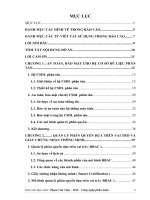
The fig. 3.1 below illustrates the decrease in price (US$ per peak watt) of solar PV with
time.
dollar
Price in US$
Watt peak power
Fig. 3.1 Average selling price trend of PV modules
As the price started falling down the demand and production of the PV modules started
growing. In 1980 ARCO Solar became the first manufacturer to produce PV modules
with peak power of over 1 Mega Watt (MW). By 1983 worldwide production of PV
modules exceeded 21.3 MW with a business volume of 250 million US$. The total
installed capacity of PV modules exceeded 1000 MW worldwide in 1999. As of end of
2002, total installed capacity of PV power exceeds 2000 MW and a business volume of
about 2 billion US$ (400 MW @ 5$/Wp).
8
Chapter 3
History and development of solar PV technology
3500
16,000
14,000
Number of Installations
12,000
10,000
8,000
Cumulative Installed
capacity (kW)
3000
2500
2000
1500
6,000
4,000
1000
500
2,000
-
0
19
92
/9
19 3
93
/9
19 4
94
/9
19 5
95
/9
19 6
96
/9
19 7
97
/9
19 8
98
/9
19 9
99
/0
20 0
00
/0
20 1
01
/0
20 2
02
/0
20 3
03
/0
20 4
04
/0
20 5
05
/0
6
D
ec
-0
6
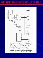
Yearly SHS Installation
20,000
18,000
Figure 3.2: Installation of SHSs - Installed till December 2006
The estimated market potential is huge and about 4,750 kWp of photovoltaic power is
currently being used in various public and private sectors (telecommunication, utility
supply, stand-alone, water supply, aviation etc.) in Nepal are shown in Table 3.2.
Table 3.2: Application of PV Power by Sector
S.N.
Service
PV Power, kWp No. of Installation
1
Telecommunications
1001
3,000+
2
Utility supply (centralised)
100
2
3
Stand-alone system
3414
93,000+
4
Water supply
120
51
5
Aviation
37
45
6
Miscellaneous
78
100+
Total
4,750
In near future more and more PV systems will be used for various types of services.
There is a plan to install 150,000 solar home systems in areas where national grid will not
reach within second phase of ESAP (March 15 2007 – March 15 2012. These facts
indicate that time has come to pay special attention for PV powered systems for income
generating activities.
9
Cumulative Installed Capacity (kWp)
Nepal could not remain in isolation with development pace of PV technology. With only
8 Solar Home System (SHS) installations in 1992/93, it increased to over 93,362 SHS by
end of 2006. The fig. 3.2 below highlights the trends in growth of SHS installations in
Nepal which constitute above 3414 kWp as of December, 2006. The trend of SHS
installation shows a steep rise after 2000 due to the subsidy policy implemented by
AEPC/ESAP. Till December 2004, 51 solar PV pumping systems have been installed, of
which 28 were installed after 2000 with subsidy provided from AEPC.
History and development of solar PV technology
Chapter 3
Institutions involved in the promotion of solar photovoltaic technology in Nepal
Various institutions are involved in the development and promotion of solar PV
technology. Bank and Financial Institutions like Agriculture Development Bank/Nepal
(ADB/N) and local commercial banks have been playing an active role in rural energy
program by financing stand-alone SHS . Non Government Organizations like Center for
Self-help Development (CSD), Center for Renewable Energy (CRE), Nepal Solar Energy
Society (NSES), have been successfully involved in limited banking activities and
mobilizing donor assistance for the promotion, development and dissemination of SHS.
Donor agencies like DANIDA/ESAP, USAID, SNV/Nepal, KfW, UNDP, UNICEF,
NORAD, European Union etc. have been contributing by providing financial support in
the form of grant-aid and soft loan. Manufacturer/Installers are manufacturing various
components of SHS and providing quality service. Government Institutions like National
Planning Commission (NPC), the Ministry of Environment Science and technology
(MOEST), the Water and Energy Commission Secretariat (WECS) of the Ministry of
Water Resources, the Ministry of Finance, etc., have influenced the RETs development’s
policies and programmes.
Applied R & D and Human Resource Development Centre/Institutions such as NAST,
NARC, RECAST, CES/IOE, KU etc., are involved in different levels of applied R & D
activities. Institutes like CES/IOE, CTEVT are involved in human resources development
at different levels for the successful planning, designing, installation, operation and
maintenance of RET projects.
RETS
In order to assure the quality of the components to be used in SHS, AEPC/ESAP has
prepared and successfully implemented a standard named, Nepal Interim Photovoltaic
Quality Assurance (NIPQA). In order to check and verify technical parameters of SHS
components a special laboratory named as Renewable Energy Test Station (RETS) is set
up and functional.
Renewable Energy Testing Station (RETS) under NAST has started to certify the various
SHS components for quality assurance. An independent body like Nepal Bureau of
Standard and Metrology (NBSM), can play a very important role in controlling the
quality of the components/devices/systems of the SHS so that healthy competition among
the suppliers can be initiated and quality assurance can be guaranteed to the users.
10
Chapter 4
Basics of Electrical Engineering
CHAPTER 4
Basics of Electrical Engineering
120 minutes
Duration:
Physical Facilities required: Class room with white board and multi-media projection
facility.
Materials required: Reference materials
Procedures: The instructor/s
a) explains the basics of electrical power system
b) provides basic knowledge on the solar radiation
Instructor: The Trainer
Reference:
1. Solar Photovoltaic System Design Manual for Solar Design Engineers,
AEPC/ESAP
2. Solar Electricity Technical Training Manual (Level 1), AEPC/ESAP.
Lesson Plan
Subchapter
Lesson details
Teaching
Methodology
Facilities
required
Duration
4.1
Electrical Power
Supply System
Solar Photovoltaic
Technology
Lecture
Class room
60 mins.
Lecture
Class room
60 mins
4.2
11
Remarks
Basics of Electrical Engineering
4.1
Chapter 4
Electrical Power Supply Systems
Electrical energy is a very convenient form of energy, which can be easily generated,
transmitted, stored and used. Any other form of energy can be easily converted into
electrical energy. An example of this is solar electricity in which the energy from the sun
(solar radiation) is converted into electrical energy by solar cells. Electricity is the branch
of science that studies the theory and practices of electrical energy. Electrical engineering
on the other hand is a branch of engineering that deals with generation, transmission,
distribution and use of electrical energy.
Electrical energy is transmitted from one point to another by means of charged particles
called electrons. There are three fundamental terminologies used in electricity: Voltage,
Current and Resistance.
Voltage
Voltage or the potential difference is a force that compels the electrons to move from one
point to another in predetermined manner. In water supply system analogy, the voltage
can be compared with the pressure of water in the storage tank that forces the water to
flow in the pipeline. The unit of measurement of the voltage is Volt and is abbreviated
and symbolically represented as ‘V’.
Current
Current is the quantity of charged particles flowing in given direction per unit time. The
current can be compared with the amount of water flowing in the pipeline per unit time.
The unit of measurement of electrical current is Ampere and is abbreviated as ‘A’.
Symbolically the letter "I" represents the current.
Resistance
Resistance is the property of the material to oppose the flow of current through it. The
unit of resistance is Ohms and abbreviated as ‘Ω’. Symbolically the letter 'R' represents
the resistance.
The electrical law that relates the above three fundamental parameters is called Ohm’s
law. According to this law, assuming that all other parameters remain constant, the
current through an electrical circuit is directly proportional to the applied voltage and
inversely proportional to the resistance of the circuit:
I V
V
(4.1.1)
I
I
I
R
R
12
Chapter 4
Basics of Electrical Engineering
The electric current is further classified into direct current (DC) and alternating current
(AC). The current is called DC if the direction of flow of current does not change with
time. It means the DC current always flows in one direction only. The voltage that causes
the flow of DC current is referred to as DC voltage. Examples of DC voltages are the
output voltages of storage batteries, DC generators etc.
If the direction of flow of current changes periodically with time then such current is
called AC current. And the voltage causing the flow of AC current is called AC voltage.
Examples of AC voltages are the city supply, output of AC generator etc. The rate or
frequency at which the direction of current changes is termed as cycle per second or
Hertz (Hz). In one cycle the current changes its direction of flow. In Nepal the frequency
of AC voltage is 50 cycles per second or 50 Hz.
The other terminologies used in electrical supply systems are power, energy, active load,
reactive load, power factor, crest factor, harmonics and Loss of Load (LoL) probability.
Power and Energy
Electrical power may be defined as the energy delivered by the electrical source
(generator) to the load (acceptor) per unit time-
P
E
t
(4.1.2)
where P is the power in Watts (W), E is the energy in Joules (J) and t is the time in
seconds.
If the supply system is DC, then the power can be expressed as the product of voltage and
current, i.e.
P V I
V2
I2 R
R
(4.1.3)
Re-writing the formula (4.1.2), we can define the energy as product of the power and
time
E Pt
(4.1.4)
Thus the energy can be defined as the power delivered to the load in given duration of
time. In electrical terms the energy is expressed in Watt- Hours (Wh)
13
Basics of Electrical Engineering
Chapter 4
Active and Reactive loads
Depending upon the characteristics of the load it can be subdivided into active and
reactive types. This classification of load type is more pertinent to AC supply than DC
supply. If the load is active (i.e. it does not contain any reactive elements like inductance
and capacitance) then the current through the load and the applied voltage cycling are in
phase. In other words the maxima and minima of the voltage and current coincides
(Fig.4.1.1).
V
Vmax
t
Vmin
No phase
difference
I
t
Fig. 4.1.1 Voltage and current waveforms for active load
Now if the load is either inductive or capacitive in nature then there will be phase
difference between the applied voltage and the current flowing through the load
(fig.4.1.2).
A purely resistive load is an example of active load. The motors, tube-lights and other
loads containing reactive elements (inductance, capacitance) are the examples of reactive
loads.
14
Chapter 4
Basics of Electrical Engineering
Real and Apparent Powers
A very important consideration for AC loads is the difference between apparent power
and real power. With purely resistive loads, the current and voltage cycling are in phase
with each other. This means that when the voltage is maximum, the maximum current is
flowing to the load. The power delivered to the load by the source (apparent or moving in
the wires and measured in VA) and consumed by the load (measured in watts) are same.
This power is called real power. Thus for a purely resistive load:
Apparent
Power or moving power VA V I
(4.1.5)
Re al power or consumed power watts V I
(4.1.6)
Here the voltage V and the current I are Root Mean Square (RMS) average values.
However with inductive loads, such as motors, there is a “pushing backwards" by the
load due to electric fields built up in the coils of the motor itself. The current cycling lags
the voltage cycling, so the current and voltage are out of phase (fig. 4.1.2).
V
t
Vmin
I
Phase
difference (φ)
t
Fig. 4.1.2 Voltage and current waveforms for reactive load
The product of the average voltage and average current is now called "apparent" power
flowing to the load. But the real power consumed in the load is less.
15
Basics of Electrical Engineering
Chapter 4
Power Factor
The amount by which the real power is less than the apparent power is related to the
cosine (cos) of the phase difference (φ) between the current and voltage. The value cos φ
is called the power factor. The real power, apparent power and the power factor is related
according to the following expression:
Re al power watts apparent power VA cos
(4.1.7)
Crest Factor
The crest factor of the voltage or current waveform is defined as the ratio of peak (or
maximum) value to the root mean square (rms or effective) value.
Harmonics
The AC voltage or current waveforms produced by the generator of electricity is
harmonic in nature. It means the instantaneous value starts from zero, reaches maximum
positive value, again drops to zero, then reaches maximum negative value and comes
back to zero again making a complete cycle (fig. 4.1.1). This cycle repeats again and
again as long as the generator continues to generate the power. Thus the instantaneous
value of voltage or current is a function of time and mathematically can be represented as
sine or cosine function of time:
here-
vt Vmax cos2ft
(4.1.8)
i t I max cos2ft
(4.1.9)
vt and i t are instantaneous values of voltage and current;
Vmax and I max are maximum or peak values;
f is the frequency in Hz and t is the time in seconds.
From the above equation, it is evident that the voltage or current waveform (we will refer
these waveforms as signals in further discussions) expressed mathematically as a sine or
cosine function contains only one frequency. This frequency is called fundamental
frequency. Now if we pass this signal through a network containing non- linearities (i.e.
through a network in which the relation between the current flowing through the network
and the applied voltage in non-linear), the signal (voltage or current) at the output of the
network will contain more than one frequency components that were not present in the
input signal. These new frequency components (sine or cosine functions with new
frequency values) are called harmonics. In general the values of the harmonics
frequencies are integer multiple of fundamental frequency.
16