BÁO CÁO THỰC TẬP TỐT NGHIỆP, We have leant about robotic arm intheory and applied to create the real product
Bạn đang xem bản rút gọn của tài liệu. Xem và tải ngay bản đầy đủ của tài liệu tại đây (723.92 KB, 27 trang )
Contents
COVER PAGE
Under the supervision and guidance of Assoc. Prof Phan Bui Khoi at Hanoi
university of Science and Technology for 4 months We have leant about robotic arm in
theory and applied to create the real product
Students: Le Xuan Tu and Pham Van Hai
Position: Student of Hanoi university of Science and Technology
Class: Mechatronics – Advanced program – K56
Tu’s phone number : +84985799987 – ID 20110735
Hai’s phone number: +841659015834 – ID 20110272
Dates: January 2016 – April 2016
We write this report when we are going to complete our final thesis. After 4 months we
had improved our skills as programming , drawing and simulating which are essential to
do our final thesis and useful for us to find a suitable after that.
This report covers the method that is used to transport blood in the hospital and how this
method can be greatly improved with the use of the robotic sorting system. The report
details the entire method of how the robot was designed, assembled, programmed, and
interfaced with software and hardware. Also how the infrared sensor was coded and how
the motors were synchronized to go to the necessary position.
CHAPTER 1: OVERVIEW ON ROBOTIC ARM
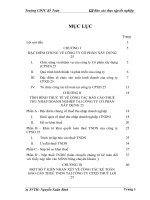
1. A brief history of medical robot
In 1985 a robot, The PUMA 560, was used to place a needle for a brain biopsy using CT
guidance. Three years later the same machine was used to perform a transurethral
resection.
Figure 1: PUMA 560
In 1987 robotics was used in the first Laparoscopic surgercy, a cholescytecotomy
In 1988, The PROBOT, developed at Imperial College London, was used to perform
prostatic surgery.
Figure 2: PROBOT
The ROBODOC from Integrated Surgical Systems was introduced in 1992 to mill out
precise fittings in the femur for hip replacement
Figure 3: ROBOTDOC
2. Research motivation
Because the advantage is that robot-assisted surgery gives the surgeon better control
over the instruments and a better view, surgeons don't have to stand all of the time
during the surgery and do not get tired as quickly. Also, robots do not make the same
mistakes that humans can make. Robots are extremely more exact, and they do not
move by accident during the surgery. This could also make patients feel less worried
before surgery. Finally, we want the life become better, especially for people health.
3. Objectives
The purpose of the project is to design a robotic sorting system for use in the medical
industry. This robot will be programmed to go through a routine to locate blood
samples, in test tubes, and transport them into their desired location. The robot will
consist of a fixed base plate, a rotating joint at gripper, a link robot arm and rotating
base. Fixed on the end of the arm will be an infrared sensor and a gripper to pick up
the test samples.
CHAPTER 2: DESIGNING, MACHINING AND PROGRAMMING
1. Designing
Figure 4: 3D model
Figure 5: Fixed base and rotating joint
Figure 6: The first link
Figure 7: Rotating joint and gripper
Figure 8: Servo motor –Mg995
2. Machining
The parts of product
3. Programming
3.1.
PIC Microcontroller
With the aid of a microcontroller the robot is able to have intelligence to complete
programmed tasks. The microcontroller can reduce product sizes, ease
implications and allow the development of intelligent computer products. This is
why a printed circuit board is necessary to minimize the microcontroller since only
part of its development board is used.
The 40-pin PIC that is used in robot design is the 16F877 embedded chip. This
chip has all necessary capabilities to provided analog to digital conversation, so
the sensors can send the precise pulse wave to reach of the motors to maneuver the
robot arm. The port A analog input and output pins RA0 are used for the sensor.
This sensor is used to detect if there are any obstacles in front of it. Once the
sensor detects a test tube the gripper hand will grip both sides of the tube and bring
it back to the desired bin.
Figure 9: PIC 16F886 pin out
3.2.
BMAX232 Converter
In order to connect a microcontroller to a serial port on a PC computer (or, in this
case, the robot arm through the SSC-32 controller) it is necessary to adjust the
level of the signals so communication can take place. The signal level on a PC is –
10 V for logic one, and +10 V for logic zero. Since the signal level on the
microcontroller is +5 V for logic one, and 0 V for logic zero, we need an
intermediary stage that will convert the levels. One chip specially designed for this
task is MAX232. This chip receives signals from -10 to +10 V and converts them
into 0 and +5 V. We installed this chip onto a board with a series of capacitors. See
appendices for circuit diagram.
3.3.
Figure 10: Constructed Converter
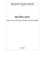
Servo Motor
A servomechanism is a device used for control by using feedback. A servo is
typically electrical in nature, and is employed in many RC vehicles such as boats
and cars. Specifically, we are using pulse-proportional servos, which use a signal
that is easy to receive and transmit. The signal that the servo receives is 0.9 – 2.1
milliseconds in length, and is repeated every 20 milliseconds. The servomotor
positions itself based on the width of the incoming pulse. Most servomotors have
up to 180 degrees of rotation, which is considered to be about 90 degrees higher
than most RC-based applications. The position of the servos is based in general on
absolute positions resulting from pulse widths. A position value of 2500 is a 2.50
millisecond pulse. The ratio of positioning is 0.09 degrees per 1 unit, for a total of
180 degrees per 2000 units. The terms pulse width and position can be used
interchangeably. The following figure illustrates the positioning of a servomotor:
Figure 11: Servomotor Pulse Diagram
3.4.
PIC16 RC Servo controller – PSC16A
The PSC16A is an integrated circuit board that controls the servomotors on the
robot arm. It mounts on the project board directly behind the robot arm itself. Each
servomotor is attached (first we ensured that the wires were long enough) to its
respective set of pins (0 through 5 were used in this case).
Figure 12: PSC16A Board
Due to its level of complexity, the PSC16A is more appropriately viewed as a
“black box” unit that simply controls the servos. A detailed circuit diagram is
included in the appendices
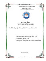
3.5.
IRPD Sensor
To allow the robot arm to detect the presence of an object at a specific location, we
used an Infrared Proximity Detector (IRPD) with a suitable range. The IRPD
employs a Panasonic PNA4602M IR sensor accompanied by two LEDs. The
module itself has several amplifiers and filters. The detector itself has what is
known as a modulated carrier, which allows for the elimination of excess sight
(such as responding to sunlight). The sensitivity of the LEDs is adjustable, and the
sight of the sensor includes the detection of objects on the left, right and
completely in the center. The information is then digitally sent to a receiving
microcontroller, which is coded to either ignore the location if a test tube is not
present, or complete a subroutine, which removes the tube if present.
Figure 13: IRPD Sensor
4. Software
4.1.
TOROBOT RIOS
(TOROBOT Robotic Arm Interactive Operating System) software (for use with
the PIC16RC controller) is used to test inputs and outputs, and to generally
configure the robotic arm (in particular the labeling and motion of the
servomotors). After each servomotor has been “plugged in” to a specific channel
on the PIC16RC board, the user is ready to begin the process. An image of the
main screen is displayed below:
Figure 14: TOROBOT RIOS interface
4.2.
TTY
The functionality of the code (to be compiled in C) was tested using TTY, which is
essentially a text-based programmer, used directly through the serial port on the
PIC16RC board. By typing lines of code in directly, the user can set the positions
on the arm. This is a lot quicker than recoding and recompiling in C each and
every time you want to make an adjustment. Also, commands are typed very
intuitively.
5. CONCLUSION
The goal of this project was to construct a model robot that could detect and
transport blood samples in the medical industry. After starting out with a vague
idea of how to program a microcontroller and formulating a plan to achieve the
created goal of the project, the robot kit was received and shortly after the robot
was created. The infrared sensor was attached to the gripper for the purpose of
locating if there is a sample ready for delivery or not. The robots motors and
sensors were then connected to the PIC microcontroller board so they could be
programmed to do the task at hand. The end result of the project was a small
prototype that was capable of sensing objects and transporting them to a desired
location. This robotic sorting system provides a more efficient and effective means
of locating and transporting blood samples. It will allow lab technicians to be
trained into different areas and shorten wait times in hospitals.
REFERNCE
www.lynmotion.com
www.robotshop.com
www.societyofrobot.com
www.mohinhrobot.com
www.titans.com
www.amazon.com
APPENDIX
Source code of Micro-controller PIC 16F877
#include <16F877.h>
#fuses HS,NOWDT,NOPROTECT,NOPUT,NOBROWNOUT
#use delay(clock=19660800)
#use rs232(baud=38400, xmit=PIN_C6, rcv=PIN_C7, PARITY=N, BITS =8)
// Motor declarations
// #0 = Base
// #1 = Shoulder
// #2 = Elbow
// #3 = Wrist
// #4 = Gripper
// #5 = Wrist Rotation
void main() {
int sensor;
set_tris_a( 0xff );
while( 1 ) {
delay_ms(6000);
/* set all of PORTA for input
*/
// Stage 1: Initial Position
printf("#1 P1000 #2 P900 #3 P1350 #4 P1500 #5 P1650 T3000\n\r");
delay_ms(4000);
printf("#0 P1000 T3000\n\r");
delay_ms(4000);
// Stage 2: Scan Position A
printf("#0 P1260 T3000\n\r");
delay_ms(4000);
printf("#1 P1100 #2 P950 T3000\n\r");
delay_ms(4000);
sensor = input_a ( ) ;
if(sensor == 0)
/* Input byte from PORTA */
{
// Stage 3: Grip Object A
printf("#1 P1250 #2 P1100 T3000\n\r");
delay_ms(4000);
printf("#4 P1100 T3000\n\r");
delay_ms(4000);
printf("#3 P1000 #2 P1100 T3000\n\r");
delay_ms(4000);
printf("#1 P600 #2 P700 T3000\n\r");
delay_ms(4000);
printf("#0 P1450 T3000\n\r");
delay_ms(4000);
printf("#1 P700 #2 P600 T3000\n\r");
delay_ms(4000);
printf("#3 P1350 T3000\n\r");
delay_ms(4000);
printf("#4 P1500 T3000\n\r");
delay_ms(4000);
}
// Stage 4: Scan Position B
printf("#1 P750 #2 P800 T3000\n\r");
delay_ms(4000);
printf("#0 P1475 T3000\n\r");
delay_ms(4000);
sensor = input_a ( ) ;
/* Input byte from PORTA */
if(sensor == 0)
{
// Stage 5: Grip Object B
printf("#1 P1000 #2 P1050 T3000\n\r");
delay_ms(4000);
printf("#4 P1100 T3000\n\r");
delay_ms(4000);
printf("#3 P1000 #2 P1100 T3000\n\r");
delay_ms(4000);
printf("#1 P600 #2 P700 T3000\n\r");
delay_ms(4000);
printf("#0 P1450 T3000\n\r");
delay_ms(4000);
printf("#1 P700 #2 P600 T3000\n\r");
delay_ms(4000);
printf("#3 P1350 T3000\n\r");
delay_ms(4000);
printf("#4 P1500 T3000\n\r");
delay_ms(4000);
}
// Stage 6: Clear for Position C
printf("#1 P600 #2 P700 T3000\n\r");
delay_ms(4000);
printf("#0 P1700 T3000\n\r");
delay_ms(4000);
// Stage 7: Scan Position C
printf("#1 P1000 #2 P850 T3000\n\r");
delay_ms(4000);
sensor = input_a ( ) ;
/* Input byte from PORTA */
if(sensor == 0)
{
// Stage 8: Grip Object C
printf("#1 P1175 #2 P1000 T3000\n\r");
delay_ms(4000);
printf("#4 P1100 T3000\n\r");
delay_ms(4000);
printf("#3 P1000 #2 P1100 T3000\n\r");
delay_ms(4000);
printf("#1 P600 #2 P700 T3000\n\r");
delay_ms(4000);
printf("#0 P1450 T3000\n\r");
delay_ms(4000);
printf("#1 P700 #2 P600 T3000\n\r");
delay_ms(4000);
printf("#3 P1350 T3000\n\r");
delay_ms(4000);
printf("#4 P1500 T3000\n\r");
delay_ms(4000);