Nghiên cứu xây dựng đường bao tải trọng giới hạn của nền đập xà lan vùng đồng bằng sông cửu long tt tiếng anbh
Bạn đang xem bản rút gọn của tài liệu. Xem và tải ngay bản đầy đủ của tài liệu tại đây (1.1 MB, 27 trang )
MINISTRY OF EDUCATION AND
MINISTRY OF AGRICULTURE AND
TRAINING
RURAL DEVELOPMENT
VIETNAM ACADEMY FOR WATER RESOURCES
NGUYEN HAI HA
RESEARCH ON BUILDING FAILURE ENVELOPE
OF MOVABLE DAM FOUNDATION
IN MEKONG DELTA
Speciality : Hydraulic engineering
Code No
: 9.58.02.02
SUMMARY OF TECHNICAL DOCTORAL DISSERTATION
Hanoi 2019
The dissertion was completed at:
VIETNAM ACADEMY FOR WATER RESOURCES
Scientific supervisors: 1. Prof. Dr. Tran Dinh Hoa
2. Dr. Tran Van Thai
Reviewer 1: Assoc.Prof. Dr. Doan The Tuong
Reviewer 2: Assoc.Prof. Dr. Nguyen Duc Manh
Reviewer 3: Assoc.Prof. Dr. Nguyen Quang Hung
The dissertation is going to be presented to academy evaluation
committee, which is held at Vietnam Academy for Water resources,
address: 71 Tay Son Street, Dong Da, Ha Noi.
In …………, 2019 at …..
The dissertation can be found at:
- National library in Viet Nam;
- Library of Viet Nam Academy for Water Resources.
-1INTRODUCTION
1.
STUDY PROBLEMS
Movable dam was first proposed and researched in the state-level
project "Researching on advanced technology to create freshwater
sources in coastal areas", code KC12-10A from 1992-1995 by Prof. Dr.
Truong Dinh Du was the chairman. The research results in this topic only
stopped at the structural principle diagram of the movable dam. This
technology was successfully applied for Phuoc Long - Bac Lieu (2004),
Thong Luu - Bac Lieu (2005) [12]. Up to now, localities such as Ca Mau,
Bac Lieu, Kien Giang have applied widely this technology, up to
hundreds of projects [18].
Due to the outstanding advantages of the movable dam are low cost,
almost do not change the natural environment due to not having to do the
construction plan and diversion. The aperture of the dam is also expanded,
thus increasing the capacity of flood drainage and protecting the
environment for the area better than the traditional sewer. Therefore, the
potential and prospect of the application of movable dam in the Mekong
Delta is very large.
2.
THE NECESSITY OF RESEARCH
Researching and proposing structural plans and solutions to build river
barrier works to control water resources has a very important strategic
meaning in socio-economic development. Movable dam is a new
technology, applied for the first time in 2003 in Bac Lieu, so far there
have been nearly 100 projects applied in the Mekong Delta. Due to the
superiority of technology, the prospect of applying this technology in the
Mekong Delta is very feasible. Therefore, the research topic "Research
on building the failure envelope of the movable dam foundation on soft
clay soils in the Mekong River Delta" to study the method of building
failure envelope of the movable dam foundation on soft clay soils
subjected to vertical loading, horizontal loading and moment. The content
and results of the thesis contribute to perfect the literature and method of
calculating the stability of the movable dam, which is both a scientific
and practical issue.
3.
RESEARCH PURPOSES
Constructing failure envelope of the movable dam on a soft clay soils
subjected to combined loads vertical loading, horizontal loading and
moment).
4.
RESEARCH OBJECTS
Foundation of movable dam placed on soft soil (without treatment)
that is subjected to combined loads including vertical loading, horizontal
loading and moment.
5.
RESEARCH SCOPES
Within the limits of this study, the author studies in scope as following:
-2- The shallow foundation is placed directly on the soft clay soil in the
Mekong Delta, covering the two sides with symmetry and ignoring the
friction effect of the side wall. The low vertical loading is consistent with
the characteristics of the dam foundation.
- Not considering the settlement deformation and consolidation over time.
6.
NEW FINDINGS OF DISSERTATION
Find out contact friction angle ( 0 ) of shallow foundation placed on
soft soil, typically in the Mekong Delta with vertical load, equal to V /
V0≤ 0.5.
Develop a tool (a software module) to build failure envelope of
movable dam in the Mekong Delta, serving preliminary design
calculations and stable inspection.
7. SCIENTIFIC AND PRACTICAL CONTRIBUTION
SCIENTIFIC CONTRIBUTION
The scientific basis for calculating the design of the movable dam
ensures stability subjected to vertical loading, horizontal loading,
moment. The research results of the dissertation contribute to adding the
theory of calculating the stability of construction on soft soil in general
and in particular the dam.
Provide a method of stable assessment of movable dam placed
directly on soft soil (untreated) subjected to vertical loading, horizontal
loading and moment.
Provide failure envelope of movable dam foundation with the contact
friction angle of 24.30 as a basis for reviewing TCVN 10398: 2015 if
necessary.
Add the limit state method for calculating in the area previously
accepted by the formula of ultimate horizontal bearing capacity: H0 =
A.su.
PRACTICAL CONTRIBUTION
Based on the tool for Abaqus software to input data, automatically
meshing, pre-processing to analyze and post-processing making failure
envelope saves a lot of time and effort in design.
Applying this result in the design of movable and similar constructions
in a convenient and easy way.
STRUCTURE OF THE THESIS
Preface
Chapter 1: Overview of research issues
Chapter 2: Research on scientific basis and method of building failure
envelope
Chapter 3: Building failure envelope
Chapter 4: Applying research results to calculation and inspection for
actual works
Conclusions and recommendations
Scientific publish
References
-3CHAPTER 1 : OVERVIEW OF RESEARCH ISSUES
1.1
GENERAL INTRODUCTION
1.1.1
Research and application of movable dam in Vietnam
Movable dam was successfully applied for Phuoc Long - Bac Lieu
(2004), Thong Luu - Bac Lieu (2005) [12]. Up to now, localities such as
Ca Mau, Bac Lieu, Kien Giang have applied widely the hydro-electric
technology, up to hundreds of projects [18].
1.1.2
Principle, structure and basic techniques of the movable dam
Specific technology principles: Settlement stability based on optimizing
light dam structure to stress on the foundation is less than bearing capacity
of soft soil without treatment. Sliding, overtuned stability principle: Use
friction between dam foundation with beneath and side soil. Permeability
stability principle: According to the horizontal length of dam foundation.
Erosion stability principle: Expanding the aperture to flow after the dam
is smaller than the allowable uneroded velocity of simple reinforcement
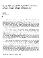
layer. There are two types of movable dam: Form 1- Closed box type
(Figure 1-1). Form 2 - Frame-slab type (Fig 1-2).
Fig 1-1 The closed box of movable dam in Bac Lieu province
1.1.3
Fig 1-2 The frame-slab type of movable dam
The situation of movable dam in the world
The dam construction works have been researched and built in the world
with the principle of reinforcement by ground reinforcement, particularly
Braddock dam (USA), reinforcing by pile foundation, which is different
-4from the research in the thesis. placed directly on the soft soil without
treatment.
1.2
SOIL CHARACTERISTICS IN THE MEKONG DELTA
According to documents, some experimental physical characteristics of
soft clay soil on representative boreholes are mentioned in the mechanical
parameters in saturated state [4], [15]. Soil investigation shows that the
soil in the Mekong Delta is very weak.
1.3
TYPES IN BEARING CAPACITY FAILURE OF FOUNDATION
Bearing capacity failure is defined as a foundation failure that occurs
when the shear stresses in the soil exceed the shear strength of the soil.
Bearing capacity failures of foundations can be grouped into three
categories, as follows: General shear failure, local shear failure, punching
shear failure [1, 10, 11, 34, 40, 56].
1.4
STABILITY OF MOVABLE DAM ON SOFT CLAY
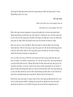
The dam is usually designed with two main combinations of working are
keeping water and saline prevention. Simultaneous impact load V, H, M.
Impact of problem model of V: H: M (Fig 1-3).
V, w
PhÝa ®ång
PhÝa S«ng
V, w
PhÝa ®ång
PhÝa S«ng
M,
M,
H, u
H, u
a. Keeping water combination
b. Saline prevention combination
Fig 1-3 Diagram of load combination effect on the movable dam
The basic dimensions of the dam as shown include: B: Width of bottom
plate, L: Length of bottom plate, Lt: Clearance width, Ht: Height of bottom
plate.
Zd
Zng
Fig 1-4 Symbol of the dimensions of the movable dam
-5According to the general construction of the dams that have been installed
directly on the soft ground, the ratio (see Annex 1 for details). Therefore,
in the dissertation, the author only focuses on researching to build a chart
of weight sacks with vertical load and (H, M) always in the same direction
(with the same sign).
1.5
1.5.1
OVERVIEW OF BEARING CAPACITY ENVELOPE
Vertical bearing capacity
Bearing capacity of shallow foundation is placed directly on the soil
surface according to the formula (1-1):
(1-1)
V0 qu N c .s c .B.su
In which:
qu is the vertical bearing capacity of the foundation (V0)
Nc : bearing capacity coefficient,
With Nc = + 2 according to the Prandtl [51]
su: undrained shear strength
sc: foundation shape coefficient, with strip footing sc = 1,
With rectangular foundation has dimension BxL, the shape factor is
determined by the formula (1-2):
B
L
Interaction between vertical and horizontal loads
(1-2)
sc 1 0, 2
1.5.2
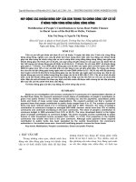
According to the research of four authors Meyerhof [49], Hansen [41],
Vesic [55] and Bolton [24], perform the relationship of and in Fig 1-5.
All four methods on different forecasts of the transition point between the
destructive point due to the vertical load and the destructive load due to
horizontal load. Meyerhof foresees the biggest transition point from
sliding failure stablility to bearing capacity stability, both Hansen and
Bolton, the transtition point is corresponding to V = V0 2 .
(0,611; 0,194)
(0,676; 0,194)
0,20
Meyerhof
H0/V0 = 1/(
0,15
(0,5; 0,194)
Bolton (1979)
H/V0
Hansen
0,10
Ph¸ ho¹i trît
(Sliding failure)
0,05
Vesic
0,00
0,00
0,20
0,40
0,60
0,80
1,00
V/V0
Fig 1-5 Failure Envelope ( V V0 , H V0 ) of strip footing, M=0
-61.5.3
Interaction between vertical load and moment
When the foundation is affected by moment, causing eccentricity e = M /
V, then the force only acts on the effective area of the foundation with the
center located at the center of the force, the effective foundation width is
B '= B - 2e. The relation between M and V is related by the formula (1-3)
M
V
V
4 1
M0
V0 V0
1.5.4
(1-3)
Interaction between vertical, horizontal loads and moment
Meyerhof [41], Hansen [49], Vesic [55] and Bolton [24] proposed the
corresponding formulas from (1-4) to (1-7) can be used to determine the
destructive contour as follows:
Meyerhof (1956)
V
o A'
(1 o ). , H A '.su
(1-4)
V0
90 A
Hansen (1970):
V
A'
1 0,5 1 1 ( H / ( A '.su ) . , H A '.s u
V0
A
(1-5)
Vesic (1975):
V
2.H
A'
1
. ,
V0
( 2). A '.s u A
H A '.su
(1-6)
Bolton (1979):
2
1
V 1 1 ( H / A '.su ) sin ( H / ( A '.su )) A '
(1-7)
. , H A '.su
V0
2
A
Word equation from (1-4) to (1-7) shows two problems: the oblique
load due to the horizontal force and the reduction of area due to the
effect of moment. The above equations are used to plot the contour of
failure envelope ( H V0 , M BV0 ).
1.5.5
Characteristics of bearing capacity envelope
With a foundation of complex load V: H: M, Hansen gives a sliding
surface contour for circular foundation according to the (1-8):
V 1 0, 2 B ' L ' 0,5 1 1 H A ' su
V0
1, 2
1 0, 4 B ' L ' A '
A
(1-8)
H A ' su
Vesic formula, giving a sliding surface contour according to the formula
(1-9).
-7 2 B' L'
H
V 1 B ' L ' 2 B ' L ' A'
1
V0
2 A ' su 3 A
(1-9)
H A ' su
The contour load of Hansen and Vesic is mainly related to the bearing
capacity envelope contour (Martin, 1994) [47]
Fig 1-6 Martin's destructive contour [47]
Results of the solution of failure envelope for the strip footing are subject
to complex loads V: H: M on clay, Ngo Tran [50] in finite element method
is performed in relation H / V0 - M / BV0 when V V0 0,5 and V V0 0,5
.
1.6
CONCLUSION CHAPTER 1
1. Overview of some type of movable dams in the world have reinforced
the treatment of the soil foundation. Meanwhile movable dams in
Vietnam are placed directly on the soil without treatment.
2. Overview of stability calculation methods of the soft soil base under
complex load and show the limitations of current methods.
3. In studies of Meyerhof, Vesic, Hansen, Bolton focused on shallow
foundation with ration V V0 > 0.5. When V V0 <0.5, it is considered as
failure mechanism due to horizontal load H0 = 0.194V0. Ngo Tran [50]
has developed the failure envelope for strip footing. To make use of the
research of Ngo Tran [50], Tran Van Thai [6] have proposed spreading
rubble mound layer 2-3cm thick at the bottom of the dam. In fact, the dam
is mainly placed directly on the soft soil, this is a problem that has not
been studied in Vietnam as well as in the world.
-8CHAPTER 2 : SCIENCTIFIC BASICS AND BUILDING FAILURE
ENVELOPE
2.1 SETTING THE PROBLEM
According to previous studies, the authors include Meyerhof [49],
Hansen [41], Vesic [55] accept that the angle of load is less than the
limited inclined angle, the ability to stand ultimate horizontal load of the
foundation. According to Martin's experiment [47], when the vertical load
(V) is small, gradually decreasing to zero, the horizontal load limit of the
foundation is also reduced to zero and not constant, so it is necessary to
study the contact friction angle of the foundation with soft clay to clarify
the effect on the limit state contour
2.2 SOIL-FOOTING INTERACTION BEHAVIOUR
The contact with the substrate according to the contact element
conforms to the Mohr-Coulomb durable standard, including the friction
part determined by the friction angle when the load is small, when the
load is large, the force is determined. The contact element according to
the instruction of ABAQUS (2013) [21] takes into account the slip
behavior on the contact surface between the structure and the background
when i = .i > max, where i is normal stress at the contact surface, max
is the shear stress limit. When the slip occurs, the i = max limit is shown
in Fig 2-1. This shear stress limit is typically introduced in cases when
the contact pressure stress may become very large (as can happen in some
manufacturing processes), causing the Coulomb theory to provide a
critical shear stress at the interface that exceeds the yield stress in the
material beneath the contact surface
Fig 2-1 Slip regions for the friction model with a limit on the critical shear
stress
Ngo Tran [50] analyzes the strip footing interaction with undrained
homogeneous soil behavior. The soil used is elastic-perfectly plastic
model. The interface is governed by the constitutive equation composed
of two parts: at a low level of compressive stress, the interface is governed
by cohesionless frictional behavior; at a high level of compressive stress,
the interface is governed by frictioless cohesive behaviour, as shown in
-9Ks= Kn=10000; c1= 0; 1 = 300; 0= 0
c2 2 3 ; 2 = 0; 0= 0,su=1,0; G=100; =0,49
Fig 2-2 Friction model by Ngo Tran (1996)
2.3 RESEARCH EFFECTS OF FRICTION ANGLE
2.3.1
Calculation model
To study the effect of friction angle to failure envelope, build a
mathematical model to analyze the problem of plane strain with
consideration foundation with friction angle and at the same time it is
possible to analyze conditions and sequence of loading different. Plane
strain with foundation B = 1m. The size of the ground model determines
the calculation results, according to ASTM D 1194-72 [22], choosing the
vertical model boundary (horizontal load effect) with the dimensions Bs
= 8B = 8 (m ), the model height is not less than twice the width of the
foundation, taking Hs = 2B = 2 (m).
2.3.2
Parameters and meshing of calculation models
Abaqus software uses finite element method with powerful
computational ability selected for analysis. The element used is the 4nodes element. Plane strain model set up as shown in Fig 2-3.
Fig 2-3 Meshing the calculation model
The soil used is the Tresca model. Mechanical and physical properties
of ground base taken for soil experiments for trough sliding model
experiment: Intensity of shear without shear su = 5 kPa, Elastic modulus
E = 1204 kPa, Unit weight of background ’= 4.3 (kN / m3).
To assess the effect of friction angle with failure envelope contour,
analyze with hypothetical friction angles 150 , 200 , 250 , 300 .
2.3.3 Method of identifying ultimate load
The relationship between the load in the compression table test with
ground displacement according to ASTM D1194-72 [22] corresponds to
four types of soil including: (I) Sand less compact, (II) Clay (sticky soil),
(III) Clay mixed with (and IV) compacted sand is shown as Fig 2-4. For
-10soils of clay type, foundation-type destructive form of subsidence type,
then the limit load determined at the point of load does not increase and
displacement increases continuously.
T¶i träng giíi h¹n
T¶i träng (kN)
C¸
t ch
Æt
ph
a
C¸
Ðm
tk
t
§Êt sÐt
chÆ
ChuyÓn vÞ (mm)
§Ê
ts
Ðt
III
II
I
IV
Fig 2-4 Relationship between load and displacement with four soil types
2.3.4 Effect of vertical ultimate bearing capacity
Analysis of vertical load bearing capacity gradually increases,
corresponding to the contact friction angle 150 , 200 , 250 , 300 .
Summary of bearing capacity coefficient Nc with contact friction angles,
Nc changes very little when angle khi increases.
2.3.5 Effect of friction angle to vertical and horizontal loads
In order to analyze the effect of friction angle on the boundary of (V,H),
analyze the vertical and horizontal loads simultaneously by assigning
vertical displacement and horizontal displacement of the foundation at the
increasing reference point, displacement ratio between displacement w
and horizontal u are fixed. With two vertical and horizontal displacement
ratios: w/u= 0,4 ; 1,0. With transposition rate w/u=0,4, relationship ratio
V V0 H V0 same Fig 2-5. With transposition rate w/u=1,0, relationship
V V0 H V0 same Fig 2-6. Relationship V V0 H V0 tend to increase
gradually when increase.
Fig 2-5 (V/Vo - H/Vo) interaction
with w/u=0,4
Fig 2-6 (V/Vo - H/Vo) interaction
with w/u=1,0
-11Thus, it can be seen that the effect of friction angle to relation
V V0 H V0 is very large because friction angle decides to transmit stress
from foundation to foundation.
2.3.6 Effect of the vertical load and moment
In order to analyze the effect of friction angle on the boundary of VHH,
analyze the vertical load and moment bearing capacity simultaneously by
assigning vertical displacement and rotation of foundation at increasing
reference point, transfer rate The position between the vertical
displacement w and the B rotation is fixed. The relationship
V V0 M BV0 was almost unchanged when increased with different
displacement ratios w / B= 0.1, 0.33, 1.0 and 3.0
2.4 EXPERIMENTAL TO IDENTIFY CONTACT FRICTION ANGLE
2.4.1 Purpose and content of the experiment
Experimental purpose
From the analysis in section 2.3, the angle greatly affects the
relationship V V0 H V0 but hardly affects the relationship V V0 H V0 .
Therefore, in order to determine tế in practice, it is only necessary to
experiment with the foundation model with vertical and horizontal load
simultaneously.
Experimental content
Building three trough models with a width of 0.2m; 0.3m and 0.4m. For
each foundation width, vertical loading and horizontal loading are carried
out to: Measure vertical load and vertical displacement of the foundation
plate. Measuring horizontal load and horizontal displacement of the
foundation plate. Observe the displacement of the foundation and
foundation (through the side glass) to determine the angle .
2.4.2 Design of experimental models
Experimental model of troughs with width of 0.2m; 0.3m and 0.4m
according to the plan of plain strain problem. In the laboratory conditions,
the compressed sheet is 0.2m wide, 0.3m wide and 0.4m wide with the
corresponding area of 0.04m2; 0.09m2; 0.16m2. Vertical loading on the
compressive plate using steel plates with dimensions 0.3m x 0.3m with a
thickness of 1cm, 2cm and 5cm for testing compression plate of 0.4m.
Transfering loading by cable system and water tank.
-12-
Fig 2-7 Diagram of testing vertical and horizontal load
2.4.3 Material specifications on the model
The physical properties of the soil were determined according to the shear
test experiment performed in the laboratory, compared with the specific
type of Mekong Delta soft soil as shown in Table 1.1.
Table 1.1 - Compare some indicators of soft soil in the model and in the South
Mechanical
Typical soft
Soft soil
TT
Symbol
Unit
indicator
soil
model
1
2
3
4
5
Natural weight
Dry weight
Initial void factor
Corner friction inside
Unit adhesive force
w
c
e0
c
kN/m3
kN/m3
độ
kPa
1516,2
8,2710,2
1,4952,214
2o30’6o
2,87,6
15,3
8,8
1,94
2o36’
3,0
2.4.4 Experimental procedures and experimental results
Perform sliding test for three types of compression plates corresponding
width B = 0.2m; 0.3m; 0.4m, for each type of compression plate tested
with three load levels, it is summarized in Table 2-2, making the
regression line V/V0 and H/V0 as shown in Fig 2-8, determining as:
tan( ) = 0.4507; corresponds to contact friction angle 24,30
Table 1.2 - Summary of experimental results
Foundation
width (m)
0,2
0,3
0,4
Type
V/V0
H/V0
V/V0
H/V0
V/V0
H/V0
Level 1
0,129
0,066
0,081
0,041
0,135
0,069
Load level
Level 2
0,184
0,093
0,180
0,075
0,205
0,102
Level 3
0,388
0,172
0,231
0,104
0,304
0,122
-13-
Fig 2-8 Relationship ( V / V0 H V0 ) corresponding to the test case
2.5
FIELD TEST
To analyze the problem of working foundation of the three-dimensional
diagram, perform the experiment to drag and slide the concrete
compressing plate with square size (0.7x0.7) m and (1.0 x 1.0.0 m) at
Bien Nhi Canal, U Minh district, Ca Mau Province. Field test results has
good agreement with laboratory experiments.
2.6
CONCLUSION OF CHAPTER 2
1. Study the behavior of contact interaction elements with soft soil base
characterized by friction angle. The description of the contact between
the structure and the background will determine the exact failure envelope
(V, H, M).
2. Select 4-nodes contact element with zero thickness to calculate the
model, Abaqus software with advantages of strong mathematical
modeling capabilities and support selected contact elements for
calculation. By numerical model, author demonstrated that friction angle
only affects relationship (V-H), has little effect on relationship (V-M).
3. Proposing to use a physical model experiment to sliding force concrete
plate in case of effect (V, H). Experimental model of sliding slide plate
with width of 0.2m; 0.3m and 0.4m that are performed with 3 levels of
vertical loading. The result of obtaining contact friction angle with
V/V0<0.5 is 24,30 . Simultaneously, the field experiment was carried
out to pull the compression plate with a width of 0.7m and 1.0m at the
scene of the foundation pit of Bien Nhi sluice gate, U Minh and Ca Mau
districts, and compare it with the experiment of sliding sliding in the
trough for matching results.
4. Proposing the experimental angle to slide sliding concrete slab on soft
soil to build failure envelope contour for soft clay soil in Mekong Delta
presented in Chapter 3.
-14CHAPTER 3 : BUILDING FAILURE ENVELOPE OF MOVABLE DAM
3.1
GENERAL
3.1.1 Purpose
The purpose of this chapter is to build failure envelope for 'dam'
foundation on soft ground with plane strain model and a space problem.
3.1.2 Construction method
Using the finite element method method using the self-developed Failure
Envelope For Dam software module connected to the Abaqus software
for analysis. Building failure envelope with plane strain. Use the
calculation results of Ngo Tran to test and calibrate the model. Build
failure envelope with for three-dimensional problem. Use field test results
to test and correct three-dimensional models.
3.2
NUMERICAL MODEL
3.2.1 Analysis model
With three-dimensional model, the square footing model B = 1m. The
platform model is similar to the analysis in Chapter 2, according to the
effect horizontal load method with dimensions Bs = 8B = 8 (m),
perpendicular dimension Ls = 5B = 5 (m), pm high Hs = 2B. Because of
the symmetry problem, in the model, only half of the model is analyzed
by horizontal load and applied moment.
3.2.2 Material model
According to the guide Abaqus 6.13 [21], the material model for the
foundation of linear elastic model, the soil uses Tresca model.
3.2.3 Finite-element mesh
In the thesis, a first-order element is used, with a plane strain using a 4node element, with a three-dimensional model using a 8-node block.
3.2.4 Methodology of building failure envelope
Stemming from the basis of studying strip footing subjected to complex
loads on clay, the theoretical solution for strip footing on clay by finite
element method based on some main tricks is exploration based on work
Displacement control according to the method of using the sliding surface
spread. Similar to vertical displacement control to determine vertical load
capacity. With each displacement standing there, check the displacement
line of the horizontal load or moment, thereby determining failure
envelope.
3.3
BUILDING SOFTWARE MODELS
3.3.1 Flow chart analysis
-15In the dissertation, Abaqus software is used to analyze deformation stress
of the strip footing interacting with the soft soil, thereby determining
failure envelope. However, the process of data entry, meshing and
processing of results is complicated and takes a long time due to the
analysis of many cases. The author of Failure software module Envelope
For Dam uses Python programming language to enter parameters, mesh
and analyze automatically.
3.3.2 Interface and analysis options
The software interface built on python uses the open source available.
The interface consists of three main windows: file management, input
data, pre-processing, post-processing.
begin
Input: B, L, Bs, Ls, Hs
, su, Eu, u
Type of failure envelope
(V-H), (V-M), (V-H-M)
False
V/V0 <= 0,5
True
Create input file
Create input file
Probe test method
Swipe test method
Run Abaqus
Solve
Run Abaqus
Solve
import and create curves
Check two Methods
False
True
Export Failure Evelope
(V-H), (V-M), (V-H-M)
end
Fig 3-1 Flowchart to construct failure envelope
-163.4
VERIFICATION OF PLANE STRAIN MODEL
3.4.1 Bearing capacity interaction between horizontal and vertical loads
Constructing failure envelope for foundation to stand vertical and
horizontal load according to two methods: displacement rate and bag load
as shown in Fig 3-2. According to the transposition ratio method,
controlling the displacement ratio w / u according to different rates: w / u
= 0.05; 0,1,0,2,0,4; 1; 2; 3. According to the bag load method, Step 1:
Carry out loading by vertical displacement w until the foundation reaches
the vertical ultimate bearing capacity, Step 2: Household load equals
displacement u, thereby building failure envelope directly from (V-H)
interaction is obtained. Perform analysis and build (V-H) interaction as
shown in Fig 3-3.
(a) Probe tests
(b) Swipe test
Fig 3-2 (V,H) interaction: displacement paths (w) and (u)
Fig 3-3 (V-H) interaction curves with =300
3.4.2 Bearing capacity interaction between vertical load and moment
Analysis of bearing capacity (V-M) according to the displacement ratio
and bag load as shown in Fig 3-4. According to the method of
transposition rate, controlling the displacement ratio w / B= 0.1, 0.2,
0.4, 0.6, 1.0. According to the bag load method, Step 1: carry out loading
by vertical displacement w until the foundation reaches the ultimate
bearing capacity, Step 2: load by rotating displacement B thereby
constructing failure envelope directly from the (V-M) interaction
obtained. Perform the above two analyzes and build the (V-M) interaction
shown in Fig 3-5.
-17-
(a)Probe tests
(b) Swipe test
Fig 3-4 (V,H) interaction: displacement paths (w) and (B)
Comparison with (V-M) interaction curves according to Ngo Tran [50]
shows similar results, small differences.
Fig 3-5 (V-M) interaction curves with =300
3.4.3 Bearing capacity interaction between vertical, horizontal loads and
moment
The method of displacement rate in the sequence of 2 steps. Step (1)
vertical loading to the vertical load level Vi by vertical displacement wi
respectively, step (2) horizontal load and moment simultaneously by
controlling horizontal displacement and rotation angle according to the u
/ B = 0.1; 0.2; 0.4; 0.6; 1.
The method of analyzing the payload in a sequence of 3 steps:
+ Step (1) vertical load level to vertical displacement wi respectively,
+ Step (2) horizontal loading by controlling horizontal displacement until
reaching the limit horizontal load.
+ Step (3) increase moment by controlling the rotation position until the
limit is reached. The analytical results obtained failure envelope contour
(V-H-M) corresponding to the Vi vertical load as shown in Fig 3-6.
-18-
Fig 3-6 Comparison these (V, H, M) interaction curves with Ngo Tran [50]
In Fig 3-6, it is shown that comparing the contour of failure envelope for
plane strain model with angle = 30o, vertical load symbol with index
(2D30) corresponding to plane strain model = 30o. The failure envelopes
are made in a smooth curves, consistent with the research results of Ngo
Tran [50] and Martin's experiments [47].
3.5
VERIFICATION OF THREE DIMENSIONAL MODEL
3.5.1 Three dimensional model
For analysis and comparison with the model experiment results in the
space math modeling room as shown in Fig 3-13. Meshing model consists
of two parts: square footing and soil. The soil model used is the Tresca
model. In software Abaqus does not declare the unit for convenience,
taking the parameters of undrained shear strength su = 1 kPa.. Unit weight
of ground soil = 4.3 (kN / m3). Although the unit weight of the base soil
is used in the analysis, however, the problem of footing analysis directly
placed on a homogeneous soil is undrained, so the bearing capacity is not
affected by ’.
Fig 3-7 Model analysis
Fig 3-8 Meshing for finite element
-19Setting up a field simulation model with a foundation of 0.7m and 1.0m
width to verify. The load order is built similar to the scenario at the scene.
Step 1: Increase vertical load on the foundation to the design load level.
Step 2: Increase horizontal load until the footing happens to slip.
3.5.2 Calculation results
Summarizing the results of mathematical model analysis for the problem
of sliding the foundation with foundation B = 1m x 1m and foundation B
= 0.7m x 0.7m. With foundation width B = 1m, the smallest error of
vertical load V1 = 11.025 (N) is 2.28%. The largest error with the vertical
load level V2 = 12862 (N) is 4.74%. With foundation width B = 1m, the
smallest error of standing load V1 = 11,100 (N) is 1.86%. The largest error
with vertical load level V3 = 18.450 (N) is 9.63%. Horizontal load is
limited according to the model calculation in accordance with the results
of the field experiment, from which the conclusion can be used to use the
angle = 24.30 to build failure envelope to check the stability of the
foundation on the soft clay soil.
3.6
BUILDING THE FAILURE ENVELOPE IN THREE DIMENSION
3.6.1 Interaction between vertical and horizontal loads
In the study of building the failure envelope for the foundation of vertical
and horizontal load, the analysis for square footing size B = L = 1 (m),
the foundation area A = 1 (m2).
3.6.2 Interaction between vertical, horizontal loads and moment
The method of constructing the failure envelope for three dimensional
problem is similar to the plane strain. According to the displacement ratio
method with the cases u / B = 0.1, 0.2, 0.4, 0.6, 1.0 in accordance with
the results of analysis according to the load, from which to build Build
the failure envelope as shown in Fig 3-9 and 3-10.
Fig 3-9 Failure envelope V V0 , H V0 , M BV0 with =24,30
-20-
Fig 3-10 Failure envelope V V0 , H V0 , M BV0 with =24,30
3.7
CONCLUSION OF CHAPTER 3
1. Build a computational model for the dam foundation under complex
load. It is recommended to use Finite element analysis, Abaqus software,
this is a powerful software in analyzing footing interaction behavior on
soil to support contact behavior including friction component and
ultimate shear strength selected for analysis.
2. Develop Failure Envelope For Dam tool in Python programming
language to automate modeling, automatic meshing and connection with
Abaqus to analyze, process and plot failure envelope. The dissertation
used this tool to build failure envelope curves with = 24.30, respectively
= 0.05 -:- 0.5. Calculation results compare with the study of Ngo Tran
[50] relatively suitable.
3. Analyzing the space problem for two plates have 70x70cm and
100x100cm wide, using field experiments to calibrate and test for
calculation errors less than 10%. The result of the numerical analysis
shows that the angle = 24.30 is suitable to build the failure envelope
contour for the general three-dimensioanl problem.
4. Establishing the process of building the failure envelope according to
the method of probe test and swipe test. The result is successful to
constructe failure envelope with = 24.30 and recommended to be used
to calculate the stability of the movable dam on the soft soil subjected to
combined loading in the Mekong Delta.
-21CHAPTER 4 : APPLICATION OF RESEARCH RESULTS ON
CALCULATION AND INSPECTION
4.1
STABILITY CHECKING USING FAILURE ENVELOPE
Applying the test formula according to QCVN 04-05 to check the stability
of the dam according to the formula (4-1) and formula (4-2):
nc .K n H H
.
m V0 V0 V , M
(4-1)
M
nc .K n M
.
m BV0 BV0 V , H
(4-2)
V0 BV0
V0 V0
Where:
H
V0 V , M
is the interpolated value in Fig. 3-22 by V and M interaction.
V0
V0 BV0
M
BV0 V , H
4.2
BV0
is the interpolated value in Fig. 3-22 by V and H interaction.
V0
V0
V0 V0
BUILDING THE CHART OF DETERMINATION OF THE
BASIC PARAMETER OF MOVABLE DAM
4.2.1
Purpose and construction method
In the preliminary design step, it is necessary to determine the basic
parameters of the stable construction project so the purpose of building a
direct survey chart of the basic parameters of the discharge according to
the water drainage width and the difference in the upstream water level
to have can determine the basic parameters of the project.
4.2.2
Diagram of effect load
Before going into construction, it is necessary to determine the load
applied to the dam construction to determine the vertical, horizontal loads
and moment.
GT
N2
P11
GCV
GXL O R
P21
P12
P12
H21
H11
Wt
Fig 4-1 Load effect on the dam in flow direction
-22-
H
Zd
Ea
Ea
Zng
pa
L
pa
Fig 4-2 Load acting on the dam in perpendicular direction
4.2.3
Stability permeability conditions
Conditions to prevent underground erosion, the length of the permeability
boundary line must satisfy:
B tt C.H
(4-3)
Where: H: The largest difference in water column of the movable dam,
m. C: is the ground-dependent coefficient. Look up the table (2-2) [17]
with soft clay: C = 2,5.
The hole width is required to determine according to the formula (4-4):
(4-4)
B 5.H
4.2.4
Summary of applied load
Before going on to build the necessary diagram to determine the load
applied on the dam. Summary of the load applied on the dam with the
width of water discharge Lt = 5m, with the width of water discharge Lt =
10m, the other tables see Appendix 2. The bottom width B is ensured as
required in the formula (4-4).
4.2.5
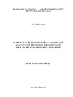
Building chart
According to the general, dam construction works without reinforcing the
foundation, the water clearance width is from 5m to 10m, H 1.5m. The
ground parameters of constructed dams are combined with su = 6 - 16
(kPa). In Fig 4-3 summarize the relationships B/L~ H(m) The opening
width are from 5.0 (m) to 10.0 (m). With increasing width, the rate B/L
decreases at each value of H, this means that the hole has a large bottom
length, the width can be reduced and ensure the necessary area to promote
anti-slip strength. of the bottom plate
Relationship between V V0 with H, with V V0 at about 0.1 to 0.25 as
shown in Fig 4-4 .The width of the water circulation increases score
V V0 can be reduced but the dam can still withstand the corresponding
water height difference. This is because the width of the water circulation
increases, the area of the bottom plate increases so the capacity of
horizontal bearing capacity is also increased.
-234.3
CONCLUSION CHAPTER 4
Applying formula (4-1), (4-2) According to QCVN 04-05, to check the
stability of the dam on the basis of the failure envelope with 24,30
and the dams already constructed so far.
- The use of Fig 4-3 and Fig 4-4 should only be applied during the
preliminary design phase for movable dam have Lt=5-:-10m and H
1,5m. After selecting the parameters, it is necessary to design in detail
and stabilize the movable dam according to the formula (4-1) và (4-2).
5,0 (m)
8,0 (m)
5,0 (m)
8,0 (m)
6,0 (m)
9,0 (m)
6,0 (m)
9,0 (m)
7,0 (m)
10,0 (m)
7,0 (m)
10,0 (m)
1,6
1,6
1,4
1,4
1,2
1,2
1,0
H
H
1,0
0,8
0,8
0,6
0,6
0,4
0,4
0,2
0,2
0,0
0,0
0,0
0,5
1,0
1,5
2,0
2,5
B/L
Fig 4-3 B/L - H (m) for movable
dam with Lt=5-:-10 (m)
3,0
0,0
0,05
0,1
0,15
0,2
0,25
0,3
V/V0
Fig 4-4 V/V0 - H for movable dam
with Lt=5,0-:-10 (m)
CONCLUSIONS AND RECOMMENDATIONS
1. Thesis results
(1) Overview of some forms of domestic and world leaks that have
reinforced the foundation. In Vietnam, most of the leaks are placed
directly on the untreated platform. Summarizing through many
constructions, most of the foundation foundations directly placed on the
weak ground are available V V0 0,5 . Previously research to consider
problem with V V0 0,5 , they often accept H 0 A.su , This formula has
not considered the effect of vertical load on the horizontal bearing
capacity of the foundation. Ngo Tran [50] has researched on this area,
however, it is only hypothetical 300 without explanation why choose
a degree 300 . In fact, the dam is primarily placed directly on the
natural platform, then 300 , This is a problem that has not been studied
in the country as well as in the world.