Basic programming simatic s7 300
Bạn đang xem bản rút gọn của tài liệu. Xem và tải ngay bản đầy đủ của tài liệu tại đây (3.41 MB, 41 trang )
By:
Andri Kuncoro
SIMATIC Overview
SIMATIC Controller (PLC)
S7-200
S7-300
S7-400
S7 – 300
Features :
Modular small controll system
Performance graded range of CPU
Extensive selection of modules
Expandable design with up to 32 modules
Backplane bus integrated in the modules
Can be networked with MPI, Profibus or Industrial ethernet
Central PG/PC connection with access to all modules
No slot restrictions
Configuration and parameter setting with the help “HW Config”
S7 – 300
Mode Selector
MRES
STOP
RUN
RUNP
=
=
=
=
Memory reset function
Stop mode, program not executed
Program execution
Program execution, read/write access
Status Indicator
SF
module
BATF
DC5V
FRCE
RUN
= Group error, internal CPU or fault in
=
=
=
=
Battery fault
Internal 5 VDC voltage indicator
FORCE
Flashes when the CPU is starting up,
then steady light in Run mode
STOP
= Show steady light in Stop mode
SF DP
= Physical bus fault
BUSF
= No configuration or incorrect
configuration
Starting with SIMATIC Manager
SIMATIC Manager menus and toolbars
Standard Library
Context-Sensitive Help in S7
F1
Creating a project
Insert Station
Starting Hardware Configuration Editor
Generating a Hardware setpoint Configuration
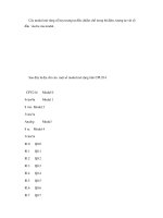
Addressing S7 Modules
S
1
2
3
4
5
6
7
8
9
10
11
PS
CPU
IM
0
4
8
12
16
20
24
28
R1
(PS)
IM
32
36
40
44
48
52
56
60
R2
(PS)
IM
64
68
72
76
80
84
88
92
R3
(PS)
IM
96
100
104
108
112
116
120
124
R
R0
Module Address Overview
Variable Addressing
2x
CPU Properties
2x
Saving the HW Configuration and Downloading it
in the Module
Inserting S7 Block
Inserting S7 Block
Block architecture and Block editor
OB
FB
FC
SFB
SFC
DB
: Organization Block
: Function Block
: Function
: System Function Block
: System Function
: Data Block
Maximun Nesting Depth :
S7-300
: 8 (16 for CPU 318)
S7-400
:24
Program Structure
Binary Operation
ASSIGNMENT
AND - OPERATION
Binary Operation
OR - OPERATION
Binary Operation
EXCLUSIVE - OR - OPERATION