Application-Guide-for-the-Automation-of-Distribution-Feeder-Capacitors
Bạn đang xem bản rút gọn của tài liệu. Xem và tải ngay bản đầy đủ của tài liệu tại đây (2.99 MB, 192 trang )
Application Guide for the Automation of
Distribution Feeder Capacitors
Technical Report
Effective December 6, 2006, this report has been made publicly available in accordance
with Section 734.3(b)(3) and published in accordance with Section 734.7 of the U.S. Export
Administration Regulations. As a result of this publication, this report is subject to only
copyright protection and does not require any license agreement from EPRI. This notice
supersedes the export control restrictions and any proprietary licensed material notices
embedded in the document prior to publication.
Application Guide for the
Automation of Distribution Feeder
Capacitors
1010655
Final Report, December 2005
EPRI Project Manager
A. Sundaram
ELECTRIC POWER RESEARCH INSTITUTE
3420 Hillview Avenue, Palo Alto, California 94304-1395 • PO Box 10412, Palo Alto, California 94303-0813 • USA
800.313.3774 • 650.855.2121 • • www.epri.com
DISCLAIMER OF WARRANTIES AND LIMITATION OF LIABILITIES
THIS DOCUMENT WAS PREPARED BY THE ORGANIZATION(S) NAMED BELOW AS AN
ACCOUNT OF WORK SPONSORED OR COSPONSORED BY THE ELECTRIC POWER RESEARCH
INSTITUTE, INC. (EPRI). NEITHER EPRI, ANY MEMBER OF EPRI, ANY COSPONSOR, THE
ORGANIZATION(S) BELOW, NOR ANY PERSON ACTING ON BEHALF OF ANY OF THEM:
(A) MAKES ANY WARRANTY OR REPRESENTATION WHATSOEVER, EXPRESS OR IMPLIED, (I)
WITH RESPECT TO THE USE OF ANY INFORMATION, APPARATUS, METHOD, PROCESS, OR
SIMILAR ITEM DISCLOSED IN THIS DOCUMENT, INCLUDING MERCHANTABILITY AND FITNESS
FOR A PARTICULAR PURPOSE, OR (II) THAT SUCH USE DOES NOT INFRINGE ON OR
INTERFERE WITH PRIVATELY OWNED RIGHTS, INCLUDING ANY PARTY'S INTELLECTUAL
PROPERTY, OR (III) THAT THIS DOCUMENT IS SUITABLE TO ANY PARTICULAR USER'S
CIRCUMSTANCE; OR
(B) ASSUMES RESPONSIBILITY FOR ANY DAMAGES OR OTHER LIABILITY WHATSOEVER
(INCLUDING ANY CONSEQUENTIAL DAMAGES, EVEN IF EPRI OR ANY EPRI REPRESENTATIVE
HAS BEEN ADVISED OF THE POSSIBILITY OF SUCH DAMAGES) RESULTING FROM YOUR
SELECTION OR USE OF THIS DOCUMENT OR ANY INFORMATION, APPARATUS, METHOD,
PROCESS, OR SIMILAR ITEM DISCLOSED IN THIS DOCUMENT.
ORGANIZATION THAT PREPARED THIS DOCUMENT
EPRI Solutions, Inc.
NOTE
For further information about EPRI, call the EPRI Customer Assistance Center at 800.313.3774 or
Electric Power Research Institute and EPRI are registered service marks of the Electric Power
Research Institute, Inc.
Copyright © 2005 Electric Power Research Institute, Inc. All rights reserved.
CITATIONS
This report was prepared by
EPRI Solutions, Inc.
942 Corridor Park Blvd.
Knoxville, TN 37932
Principal Investigators
D. Crudele
T. Short
This report describes research sponsored by the Electric Power Research Institute (EPRI).
The report is a corporate document that should be cited in the literature in the following manner:
Application Guide for the Automation of Distribution Feeder Capacitors, EPRI, Palo Alto, CA:
2005. 1010655.
iii
PRODUCT DESCRIPTION
This is the fourth and final report in the Electrical Power Research Institute’s (EPRI’s) capacitor
reliability study, and it deals with automating distribution capacitors. Prior reports dealt with
nuisance fuse operations, operating and construction practices, and lighting protection and
grounding of capacitor controllers. This guide is concerned with applying automated switched
capacitors to distribution systems. Consideration is given to applications involving locally
controlled capacitor banks and to systems utilizing centrally controlled, switched capacitor
banks. The guide is designed for the distribution engineer considering capacitor automation for
his or her system.
Results and Findings
The Application Guide for the Automation of Distribution Feeder Capacitors attempts to provide
the utility engineer with the background needed to sufficiently understand automated capacitor
control and the ways it might be applied to his or her distribution system. This guide discusses
commonly applied capacitor control schemes, including both locally applied and centralized
control schemes. The reader is presented with resources for locating a variety of capacitor
control equipment currently available from several prominent manufacturers in this area. This
guide also discusses the issues of system integration, capacitor protection, control schemes, and
capacitor-related power quality issues.
Challenges and Objectives
This guide is intended to provide the necessary background for a distribution engineer to quickly
acquire a working knowledge of the issues associated with capacitor automation, including:
•
Types of capacitor automation schemes (local control versus centralized control)
•
Ways capacitor automation is employed
•
Advantages and drawbacks of different types of capacitor controls
•
Supervisory control and data acquisition (SCADA) systems for capacitor control
•
Communication systems used for capacitor control
•
Capacitor bank sizing and protection issues
•
Capacitor power quality issues
Due to the potential variability of the capacitor control system from one utility to the next, it is
difficult to assign costing figures that will cover all capacitor automation systems. Therefore, this
Guide attempts to describe the various payback streams that come from implementing
v
sophisticated capacitor automation schemes. This will allow readers to assign their own dollar
savings to each category and determine their own potential payback.
Applications, Values, and Use
Distribution automation has emerged as a tremendous resource for increasing efficiency and
decreasing operating costs for the modern electric utility. Advancements in communication and
control technologies have made many automation programs—never-before available—a part of
the daily operation of utilities around the United States. Among the array of attractive
distribution automation technologies are automated capacitor controls, which lead the way as
perhaps the most desirable control technology in terms of increasing operating efficiency and
providing a quick return on utility investments. This guide provides a detailed look at many of
the aspects of distribution capacitor automation in order to help the distribution engineer quickly
gain the background needed to seriously examine capacitor automation applications.
EPRI Perspective
Capacitor automation technology has advanced greatly in recent years. Utilities now have access
to intelligent, automated capacitor controllers from numerous manufacturers. Many controllers
on the market also have advanced communication capabilities allowing them to be easily
integrated into SCADA systems. These advances in capacitor automation technology, coupled
with the modern utility’s need to operate ever more efficiently, have utilities taking a closer
examination of how capacitor automation can benefit their distribution systems. This guide is
intended to aid the distribution engineer or planner in determining how capacitor automation can
be a benefit to their distribution system as well as provide the background information and
automation fundamentals needed to seriously examine how to automate the capacitors on their
system.
Approach
The project team began by researching all available information on state-of-the-art capacitor
automation systems currently in use by utilities. From this research, sections have been added to
discuss the various types of control schemes used for capacitor automation and local control
verses centralized control topologies. The project team also researched SCADA systems used for
modern capacitor automation and have attempted to provide a detailed overview of SCADA
systems so readers may better understand how these systems can be utilized in distribution
automation.
No discussion of utility SCADA is complete without examining the many communication
channels available to transfer data from the central station to field units and back. Therefore, one
chapter of this Guide is dedicated to examining SCADA communication media, with particular
attention paid to which companies currently offer commercial communication services for each
medium. Finally, basic capacitor application information is presented in chapters dedicated to
capacitor installation sizing, location, protection, and power quality issues.
Keywords
Capacitor automation
Switched capacitor
SCADA
VARs
vi
Capacitor control
Distribution automation
Volt/VAR management
EXECUTIVE SUMMARY
The EPRI Capacitor Reliability Study
Utilities have a substantial investment in distribution line capacitors. These investments are
justified, based on certain derived benefits to the power delivery system, the utilities, and the
end-users. When capacitors are not available due to some failure or operating error (or are
otherwise off-line), the anticipated benefits will not be achieved. Experience at utilities reveals
that capacitors are unavailable for operation too frequently. This project series was established,
therefore, to improve capacitor reliability. Initial scoping helped identify and prioritize several
issues affecting the overall reliability of capacitors. The EPRI capacitor reliability study spans
several years, from 2002 through the present. Each year a report is prepared dealing with a
different aspect of capacitor reliability. Reports from previous years have covered:
•
Utility Survey and Literature Search (2002): This study was a utility survey and literature
search to assess the issues related to the reliability of switched capacitor banks used in
distribution systems (EPRI 1001691).
•
Fusing and Transmission Support (2003): This study investigated causes of nuisance fuse
operations on capacitor banks. Additionally, utility practices for providing transmission level
VAR support with distribution capacitors were reviewed, and additional utility needs were
assessed (EPRI 1002154).
•
Grounding and Lightning Protection of Capacitor Controllers (2004): Investigate the two
primary factors influencing the magnitude of surges reaching capacitor controllers and
provide controller mounting and wiring configurations for minimizing surge magnitude. The
first recommendation involves the physical location at which the capacitor controller should
be mounted with regard to the control power transformer (CPT) from which it draws power.
The second recommendation involves grounding considerations for the controller supply
power (EPRI 1008573).
This year’s report, 2005, examines automating switched capacitors at the distribution level. This
guide attempts to provide the utility engineer with the background needed to sufficiently
understand automated capacitor control and the ways it could be applied to their distribution
system. This guide discusses commonly applied capacitor control schemes, including locally
applied control and centralized control schemes. The reader is presented with a variety of
resources for locating capacitor control equipment from several prominent manufacturers in this
area. This guide also discusses the issues of system integration, capacitor protection, control
schemes, and capacitor-related power quality issues.
vii
Project Objectives
The primary focus of this guide is to provide distribution engineers with the necessary
information to examine options for applying a switched capacitor automation scheme on their
distribution system. This guide provides a detailed discussion of the all the key aspects of
distribution capacitor automation, including:
•
Control Schemes: VAR, voltage, current, time, temperature, date, and combination control
programs
•
Control Intelligence Location: Local control, central coordinated control, local control with
central station override
•
Supervisory Control and Data Acquisition (SCADA) Systems: Components commonly found
in SCADA-based capacitor control systems, with examples cited from prominent
manufacturers
•
Voltage and Current Measurements: Information on line parameters typically measured and
the potential for modern capacitor controllers to gather and report a wide array of line data to
aid distribution engineers in investigations beyond VAR management
•
Capacitor Sizing and Placement: Detailed information size and placement of capacitor
banks on the distribution system
•
Capacitor Installation Protection: Detailed information on proper application of fuses to
protect capacitor banks, with additional information regarding protecting capacitor
controllers from line surges and lighting strikes
Background
There is considerable industry activity in applying distribution feeder capacitors. Automated line
capacitors are being added by many utilities. Automation and communication technologies are
more advanced, more readily available, and more reasonably priced than even before. These
advancements in automation control and communication allow utilities to operate switched
distribution capacitors in a manner that has never before been possible. Utilities are using
capacitors in a variety of ways—to supplement transmission VARs, as substitutes for substation
capacitors, to manage distribution voltage profiles, and to reduce line losses. Communication
technology allows centralized control of distribution capacitors as if they were substation banks.
This adds the benefit of having the capacitors located closer to the loads they service, thereby
further improving their operating efficiency.
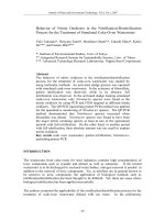
A typical switched capacitor bank installation is shown in Figure ES-1. Although Figure ES-1
only shows the capacitor assembly near the pole top, the capacitor controller is mounted lower
on the pole, approximately 10 ft (3 m) above the ground. There are many types of controllers on
the market, with many different configurations.
viii
Figure ES-1
Example of a Switched Capacitor Bank Configuration
Distribution line capacitors provide tremendous benefits to distribution system performance by
providing volt-ampere-reactives (VARs) at or near the VAR-consuming loads—and they do this
at a low cost. The main benefits that capacitors provide are:
•
Reduced Losses and Increased Capacity: By canceling the reactive power to motors and
other loads with low-power factor, capacitors decrease the line current. Reduced current frees
up capacity. Reduced current also significantly lowers I2R line losses.
•
Reduce Voltage Drop: Capacitors provide a voltage boost that cancels part of the drop
caused by system loads. Switched capacitors serve to regulate voltage on a circuit, having an
ancillary benefit of reducing the number of operations on voltage regulators, both line (and to
a lesser to degree) substation regulators and load-tap-changers (LTCs). This reduces
maintenance costs on regulators and LTCs.
•
Reduced Cost of Production or Cost of Purchased Power: Because line capacitors provide
VARs, generators no longer have to produce VARs, thus capacity is freed up to produce
more real power. (In addition, transmission and distribution lines no longer have to transport
those VARs.)
If applied and controlled properly, capacitors can significantly improve the performance of
distribution circuits. But if not properly applied or controlled, the reactive power from capacitor
banks can create losses and can also create high voltages. The most danger of overvoltage is
under light loads. Good planning helps ensure that capacitors are sited properly. Compared to
ix
simple controllers (like a time clock), more sophisticated controllers (such as a two-way radio
with monitoring) reduce the risk of improperly controlling capacitors.
Capacitors work their magic by storing energy. Capacitors are simple devices—two metal plates
sandwiched around an insulating dielectric. When charged to a given voltage, opposing charges
fill the plates on either side of the dielectric. The strong attraction of the charges across the very
short distance that separates them creates a tank of energy. Capacitors oppose changes in voltage.
It takes time to fill up the plates with charge; and once charged, it takes time to discharge the
voltage.
On ac power systems, capacitors don’t store their energy very long—just one-half cycle. Each
half cycle, a capacitor charges up and then discharges its stored energy back into the system. The
net real power is zero. Capacitors provide power just when reactive loads need it. At the time a
motor with low-power factor needs power from the system, the capacitor is there to provide it.
Then in the next half cycle, the motor releases its excess energy, and the capacitor is there to
absorb it. Capacitors and reactive loads continue to exchange this reactive power. This benefits
the system because that reactive power (and extra current) does not have to be transmitted from
the generators all the way through many transformers and many miles of lines; therefore, the
capacitors can provide the reactive power locally. This frees up the lines to carry real power that
actually performs work.
Control Strategies
Local Control
Switched capacitor banks are controlled either locally or through centralized system controls. As
the name implies, local controls sit on or near the same pole as the capacitor bank and govern the
switching operations of only one local bank. There are several local control strategies available
for switched capacitor banks, as shown below (Marx 2003); (Short 2004b):
•
VAR Control: The capacitor is switched on and off at an optimum point in the load cycle
based on VAR measurements on the line. VAR control is the most efficient control strategy
for maximizing the reduction of loss and demand on feeders having only one capacitor bank
installed. However, VAR control is susceptible to interaction from downstream capacitor
banks (downstream banks affect the reactive current flow upstream of their location).
Therefore, when applying multiple capacitor banks using VAR control on a single feeder, the
controls should be set such that the bank furthest downstream comes on-line first, followed
by the next upstream bank, and so on. Furthermore, the banks should then trip in the opposite
order by which they switched in (that is, the last to switch in should be the first to trip out).
•
Current Control: The capacitor is switched on and off based on the line current measured
downstream of the capacitor. Reactive current can be determined from line current when the
power factor of the line is known. Current control engages the capacitor during periods of
heavy loads which generally have the greatest VAR requirements. Although not as effective
as VAR control schemes, current control provides a fairly good combination of loss
reduction and voltage control.
x
•
Voltage Control: The capacitor is switched on and off based upon the voltage. To prevent
excessive operations, threshold minimum and maximum voltages are programmed into the
controller, as well as time delays and bandwidths. Voltage control is best suited for
applications in which the capacitor mainly provides voltage profile control and regulation.
Voltage controls can be influenced by both upstream and downstream capacitors, since they
affect the voltage along the whole line. Voltage regulators can also cause capacitor control
pumping problems. In general, capacitor controllers using voltage control schemes should be
configured to operate prior to the local voltage regulators. In this manner, the voltage
regulators operate only when the capacitors cannot maintain the desired voltage profile.
It should also be noted that voltage control schemes provide the greatest value on feeder
sections further from the substation. The capacitor should have a minimum effect of 2 V (on
120 V reference), and the cap on-to-off difference should be approximately 1.5 times the
expected voltage rise when the bank is switched on (Marx 2003).
•
Time-Clock Control: The controller switches the capacitor, based upon the time of day.
Time-clock control represents the most basic approach for switching a capacitor on and off.
Most time-clock controllers allow for programmable on and off time settings, as well as
settings for weekends and holidays. While this is the least expensive control option, it is also
the most susceptible to energizing the capacitor at the wrong time; because switching is
based on expected line conditions rather than on measured conditions. Loads can be different
than those anticipated at any time, but holidays and weekends are particularly challenging.
Time-clock controllers, which are susceptible to mistaken time settings and inaccurate
clocks, can switch the capacitor at times other than those planned. Since time control is not
based on line measurements, time-clock controls are not susceptible to interaction with other
banks.
•
Temperature Control: The capacitor is switched based upon the temperature. Like
time-clock controls, temperature controllers also provide a very basic level of capacitor
control. Typically, temperature controls are set to turn the bank on at 85-90º F (29.4–32.2º C)
and turn the bank off again at 75-80º F (23.8–26.7º C). Since temperature control is not based
on line measurements, they are not susceptible to interaction with other banks.
•
Power Factor Control: The capacitor is switched based upon the power factor measured on
the line. This method of control is rarely used by utilities, mostly owing to the fact that power
factor is not a suitable parameter for controlling capacitor switching. Since power factor is
not necessarily an indication of load, power factor controls may fail to switch in the capacitor
during high loads, if the power factor is also high. To compensate for this shortcoming,
power factor controls may also incorporate voltage and current overrides, both of which
make the system more complicated. Due to these reasons, VAR control is typically used
rather than power factor control.
Many controllers offer some or all of these control strategies. Many are usable in combination;
for example, they will turn capacitors on for either low voltage or high temperature.
xi
Centralized Control
Advances in wireless communication technology have made remote capacitor control more
achievable and more economical than ever before. Cellular phones, pagers, and other wireless
technologies have become ubiquitous in modern life, turning up in new applications, such as
remote capacitor control. There are several control schemes available for remotely controlled
capacitor installations, including:
•
Operator Dispatch: Most schemes allow operators to dispatch distribution capacitors. This
feature is one of the key reasons utilities automate capacitor banks. Operators can dispatch
distribution capacitors just like large station banks. If VARs are needed for transmission
support, large numbers of distribution banks can be switched on. This control scheme is
usually used in conjunction with other controls.
•
Time Scheduling: Capacitors can be remotely switched, based on the time of day and
possibly the season or temperature. While this may seem like an expensive time control, it
still allows operators to override the schedule and dispatch VARs as needed.
•
Substation VAR Measurements: A common way to control feeder capacitors is to dispatch
based on VAR/power factor measurements in the substation. If a feeder has three capacitor
banks, they are switched on or off in some specified order, based on the power factor on the
feeder measured in the substation.
•
Capacitor Location VAR Measurements: The continuing advancement or capacitor
controller capabilities, coupled with increasing capability for two-way data transfer, are now
making it possible for capacitor controllers to measure line parameters at their location and
report that data back to a central station controller. The central station controller examines
the data from each capacitor location (and possible the substation as well) and makes
decisions for switching each capacitor individually. A major detractor of this type of
operation is that current transformers (CTs) need to be installed at each site in order to make
VAR measurements; and this carries a significant equipment cost—much higher than just
measuring at the substation.
•
Other Methods: More advanced (and complicated) algorithms can be used to dispatch
capacitors, based on a combination of local VAR measurements and voltage measurements,
along with substation VAR measurements.
All of the control strategies mentioned above will typically utilize a local voltage override
feature, especially if the controller has only one-way communication capabilities. Local voltage
override prevents the capacitor from switching if doing so will push the voltage beyond limits set
by the user. Additionally, most controllers used for centralized control will have fail-safe modes
in which they will revert to a type of local control (voltage, current, VAR, time, temperature,
combination, and so on.) if communication with the central station is lost.
Capacitor Controllers
The capacitor controller is really the backbone of the automated switched capacitor system. Both
local control schemes and centralized control schemes utilize a local capacitor controller. At the
xii
most basic level, the controller provides the interface to the capacitor switch, telling it when to
open and close. In local control schemes, the controller provides the switching logic. In central
control schemes, the controller 1) houses and interprets the signals provided by the data radio, 2)
provides switching override functions based on local conditions, and 3) provides switching logic
in the event that communication with the central station is lost.
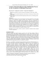
There are many models of capacitor controllers available from numerous manufacturers. The
controllers are typically packaged in weatherproof enclosures and are intended to be mounted on
the same pole as the capacitor bank and switch. Some examples of capacitor controllers from
various manufacturers are shown in Figure ES-2.
Figure ES-2
Examples of Capacitor Controllers from Various Manufacturers
Since there is wide variability in capacitor control needs from one utility to the next, there is also
a corresponding wide variety of features among currently produced capacitor controllers. Most
manufacturers try to cover most, if not all, of the possible features that a utility may require,
including:
•
Communication: None (local control only), one-way, two-way
•
Communication Channel: Radio, cellular, fiber optic, paging, copper line, and so on.
•
Control Type: Volt, current, VAR, time, temperature, combination control
•
Monitoring: Some controllers with two-way communication ability to also report data on a
variety of parameters: voltage, current, watts, power factor, temperature
•
Data Storage: Some controllers can store operational data locally for retrieval by utility field
personnel via laptop computer
•
Reverse Power Detection: As part of their monitoring capability, some controllers can detect
reverse power conditions on the feeder. Additionally, some controllers have the functionality
to calculate proper set points and compensate for atypical line measurements during reverse
power flow conditions.
•
Neutral Current Monitoring: Monitoring the capacitor bank neutral current can help
diagnose problems, such as blown fuses, failing capacitor units, and high harmonic currents.
Further information on neutral current monitoring is available in Chapter 5, “Voltage and
Current Measurements.”
xiii
Most controllers have functionality for all local control types (volt, current, VAR, time,
temperature, and so on.); and they can often run a combination program incorporating two or
more of these parameters in a hierarchical manner. Most manufacturers also cover both local
control and centralized control with one- or two-way communication capabilities, frequently by
providing different models, each with distinct communication capabilities.
SCADA Systems
Basic SCADA systems, also referred to as telecontrol systems, consist of a master station(s)
communicating with one or more remote terminal units (RTUs) to provide data acquisition and
control functionality between a central location and dispersed field units. A very simplistic
diagram of a SCADA system is provided in Figure ES-3 to illustrate the concept of centralized
control of dispersed field units. The communication channel between the master controller and
remote units can be any one of a number of technologies, including radio, cellular, modem, or
hard-wired networks. There are numerous protocols available that define how communications
between the master station and remote units should be structured over the communication
channel, although the DNP3 protocol tends to dominate new capacitor control systems. The
master station runs application software that provides the human-machine interface and also
provides the functionality to perform the specific tasks for which the SCADA system is used
(that is, capacitor control, process control, data acquisition). Alternatively, in larger multifunction SCADA systems, the master station may provide overall coordination and data archival,
while dedicated servers run individual function programs, such as the DCC system illustrated in
Figure ES-3.
Figure ES-3
Components of a Basic SCADA System
Communication Technology
There are several technologies currently in use for communicating with the capacitor controllers.
Some offer one-way communication while others offer two-way communication. With one-way
communication, commands can be dispatched to the capacitor controllers in the field, but there is
xiv
no communication from the field back to the control center. Two-way communications offer data
flow both from the command center to the field units and from the field units back to the
command center. The technologies used for centralized capacitor control communications
include:
•
900-MHz Radio: These systems are very common and widely applied for centralized
capacitor control. There are several spread-spectrum radios available that cover 902-928
MHz applications. Implementing 900-MHz radio control on a private network requires
infrastructure, including towers.
•
Pager Systems: Pager systems offer inexpensive options, especially for systems with
infrequent switching. These systems are mostly one-way, but there are some two-way pager
systems available. Most commercial paging systems can be utilized, however that means that
while one-way coverage is rather wide-spread, two-way systems tend to be limited to clusters
around major cities.
•
Cellular Phone Systems: These systems use commercial cellular networks to provide twoway communications. Many vendors offer modems that are compatible with several cellular
networks, and coverage is typically very good.
•
Cellular Telemetric Systems: These use the unused data component of cellular signals that
are licensed on existing cellular networks. They allow only very small messages to be sent to
perform basic capacitor automation needs. Coverage is typically very good, the same as
regular cellular coverage.
•
Very High Frequency (VHF) Radio: Inexpensive, one-way communications are possible
with VHF radio communication. VHF radio bands are available for telemetry uses such as
this. Another option is a simulcast frequency modulation (FM) signal that uses extra
bandwidth available in the commercial FM band.
Economics
Utilizing automated, intelligent capacitor bank switching controls provides several channels of
payback that generally yield a very fast return on investment. In fact, there are few capital
projects that a utility can undertake that provide a faster return. Automated capacitor control
generates three main areas of cost savings as follows:
•
Energy Savings: In this project, energy savings (also termed loss reduction) refers to
reducing line and transformer losses by using intelligent capacitor control to effectively
reduce the amount of reactive current flowing in the line. Since energy wasted in heating
conductors cannot be delivered to a customer, it generates no revenue. It also contributes to
fatigue on line conductors and apparatuses through heating.
•
Capacity Savings: Improving the line power factor through proper application of capacitors
reduces the total line current, thus reducing kVA demand. The benefits provided by released
capacity are twofold. First, releasing line capacity allows more billable energy to be
transferred to customers, thus increasing the revenue that the line can generate. The second
benefit of releasing line capacity is that it can enable the deferral of equipment upgrades.
Improving the power factor releases transmission and generation capacity as well as
distribution capacity.
xv
•
Operation and Maintenance Savings – Required labor hours can be greatly decreased when
upgrading to intelligent centralized capacitor controls via supervisory control and data
acquisition (SCADA) systems. SCADA control greatly reduces labor costs by allowing for
centralized switching control and monitoring of all capacitor banks. This dramatically
reduces travel time as well as time spent adjusting capacitor bank controls. Additional cost
savings come from the ability to remotely monitor capacitor bank status to determine when
capacitors fail. This also eliminates the need to have technicians travel to capacitor
installations to annually inspect bank functioning, which amounts to a considerable savings
in work-hours. The ability to quickly identify and fix failed capacitors also means that fewer
capacitors would need to be installed in the system, since a very high percentage would be
operational all the time. Over time, then, some capacitor banks could be taken out of service
and used for future installations, providing a capital cost savings.
Capital costs for capacitor control systems can vary greatly, depending on the level of
sophistication being employed and what, if any, existing utility infrastructure can be utilized for
the system. However, the level of existing hardware also plays a role in determining the design
of the capacitor control system. For example, if a utility already has an extensive 900-MHz radio
system in place, then they will likely utilize that system for communication in their capacitor
control system. If a utility does not have any communication system is place, they may opt for a
commercially provided communication system (such as a cellular control channel) rather than
building their own communication network. Even utilities that have a communication network in
place may opt for commercially provided communications, since commercial systems require no
infrastructure maintenance from the utility.
xvi
CONTENTS
1 PROJECT OVERVIEW...........................................................................................................1-1
Control Strategies..................................................................................................................1-3
SCADA and Communications ...............................................................................................1-4
Project Objectives .................................................................................................................1-5
2 CAPACITOR SIZING AND PLACEMENT .............................................................................2-1
Introduction ...........................................................................................................................2-1
Capacitor Ratings..................................................................................................................2-5
Released Capacity ................................................................................................................2-9
Voltage Support ..................................................................................................................2-11
Reducing Line Losses .........................................................................................................2-13
Energy Losses ....................................................................................................................2-16
Grounded versus Ungrounded ............................................................................................2-17
Impact of Switching on Capacitor Sizing and Placement ....................................................2-19
Switched Capacitor Bank Equipment Mounting Considerations .........................................2-19
Optimal Capacitor Placement Computer Programs ............................................................2-23
3 AUTOMATION STRATEGIES................................................................................................3-1
Best Use of Distribution VARs...............................................................................................3-1
Conservation Voltage Reduction...........................................................................................3-1
Optimizing Power Factor at the Substation ...........................................................................3-3
Distribution Capacitors for Transmission VAR Support.........................................................3-3
KCPL ................................................................................................................................3-3
Idaho Power .....................................................................................................................3-4
Cinergy Corp ....................................................................................................................3-5
Georgia Power..................................................................................................................3-6
Summary of Utility Practices ........................................................................................3-7
Transmission versus Distribution Optimization ............................................................3-8
xvii
Switching Control .........................................................................................................3-8
Station versus Feeder Evaluation ..............................................................................3-11
Automation and Other Infrastructure Requirements............................................................3-12
4 CONTROL STRATEGIES ......................................................................................................4-1
Control Strategies..................................................................................................................4-1
Local Control ....................................................................................................................4-1
Centralized Control...........................................................................................................4-4
Coordination of Switched Capacitors and Voltage Regulators..............................................4-6
Coordination of Switched Capacitors and Distributed Generation ........................................4-7
5 VOLTAGE AND CURRENT MEASUREMENTS....................................................................5-1
Basic Measurements.............................................................................................................5-1
Neutral Monitoring .................................................................................................................5-4
6 COMMUNICATION TECHNOLOGIES ...................................................................................6-1
Communications Technologies .............................................................................................6-1
Spread Spectrum 900-MHz Radio Systems..........................................................................6-4
Pager Systems ......................................................................................................................6-5
FLEX™ Paging Protocol...................................................................................................6-6
Cellular Systems ...................................................................................................................6-7
Cellular Data Channel Systems........................................................................................6-7
Cellular Digital Packet Data..............................................................................................6-9
Cellular Antennas .............................................................................................................6-9
Commercial Support for Communication Planning and Analysis ........................................6-11
7 CAPACITOR CONTROLLERS AND SCADA SYSTEMS......................................................7-1
Capacitor Controllers.............................................................................................................7-1
SCADA Overview ..................................................................................................................7-8
Master Stations ...................................................................................................................7-10
Protocols .............................................................................................................................7-10
Distributed Network Protocol (DNP3) .............................................................................7-11
IEC 60870.......................................................................................................................7-13
Utility Communications Architecture...............................................................................7-15
MODBUS........................................................................................................................7-16
RTUs, IEDs, and PLCs........................................................................................................7-16
xviii
SCADA Security ..................................................................................................................7-17
8 SOFTWARE AND DATA APPLICATIONS ............................................................................8-1
Capacitor Control Software for SCADA Systems..................................................................8-1
Device and Data Management Software...............................................................................8-3
Human-Machine Interface Issues..........................................................................................8-4
9 CAPACITOR AND CONTROLLER SURGE PROTECTION..................................................9-1
Primary Arrester Lead Length and Coordination with Fuses.................................................9-1
Lead Length Considerations.............................................................................................9-1
Arrester Installation Clearance Considerations ................................................................9-5
Capacitor Controller Surge Protection...................................................................................9-6
Modeling of Lightning Surges Originating on the Primary Conductors .............................9-7
Preliminary Recommendations.......................................................................................9-10
Key Considerations ........................................................................................................9-12
Controller Mounting Location .....................................................................................9-12
Ground Loops and Shielding .....................................................................................9-12
Arrester Lead Length .................................................................................................9-15
Auxiliary Surge Suppression......................................................................................9-15
Pole Ground Resistance ............................................................................................9-19
Consult the Manufacturer...........................................................................................9-19
Installation Guidelines................................................................................................9-19
10 CAPACITOR FUSING ........................................................................................................10-1
Fusing Guidelines................................................................................................................10-1
Reasons for Relaxing Fusing ..............................................................................................10-4
Maximum Fuse Sizes ..........................................................................................................10-6
Nuisance Fuse Operation....................................................................................................10-8
Outrush and Inrush..............................................................................................................10-9
Fuse Installation Issues.....................................................................................................10-16
Proposed Fusing Guidelines .............................................................................................10-18
11 CAPACITOR BANK POWER QUALITY AND RELIABILITY ISSUES..............................11-1
Harmonics ...........................................................................................................................11-2
Solutions to Harmonics...................................................................................................11-5
Switching Surges.................................................................................................................11-6
xix
Adjustable Speed Drive (ADS) Tripping ..............................................................................11-9
Solutions to Switching Transients .....................................................................................11-10
Telephone Interference .....................................................................................................11-12
Voltage Flicker ..................................................................................................................11-13
12 ECONOMICS......................................................................................................................12-1
Energy Savings ...................................................................................................................12-2
Capacity Savings.................................................................................................................12-2
Operation and Maintenance Savings ..................................................................................12-4
Estimated Cost Breakdown .................................................................................................12-4
13 REFERENCES ...................................................................................................................13-1
xx
LIST OF FIGURES
Figure 1-1 Example of Switched Capacitor Bank Configuration ................................................1-3
Figure 2-1 Capacitor Components.............................................................................................2-2
Figure 2-2 Overhead Line Capacitor Installation .......................................................................2-3
Figure 2-3 Released Capacity with Improved Power Factor....................................................2-10
Figure 2-4 Extra Capacity as a Function of Capacitor Size .....................................................2-10
Figure 2-5 Voltage Profiles After Addition of a Capacitor Bank ...............................................2-12
Figure 2-6 Optimal Capacitor Placement Using the “2/3’s” Rule .............................................2-14
Figure 2-7 Placement of 1200-kVAR Banks Using the ½-kVAR Method.................................2-15
Figure 2-8 Sensitivity to Losses of Placing One Capacitor on a Circuit with a Uniform
Load .................................................................................................................................2-16
Figure 2-9 Example of Real and Reactive Power Profiles on a Residential Feeder on a
Peak Summer Day with 95% Air Conditioning (Data from East Central Oklahoma
Electric Cooperative, Inc.) ................................................................................................2-17
Figure 2-10 Comparison of Grounded-wye and Ungrounded-wye Banks During a Failure
of One Unit .......................................................................................................................2-18
Figure 2-11 Example Switched Capacitor Bank Installation Courtesy of Donald M. Parker
at Alabama Power............................................................................................................2-20
Figure 2-12 Generic Switched Capacitor Bank Equipment Configuration ...............................2-21
Figure 2-13 Typical Layout of Pole-Top Equipment in a Switched Capacitor Installation
Courtesy of Donald M. Parker at Alabama Power............................................................2-22
Figure 2-14 Example Location of Fuses and Lightning Arresters in a Switched Capacitor
Installation Courtesy of Donald M. Parker at Alabama Power .........................................2-22
Figure 3-1 Three Steps for Applying Capacitors for Peak Shaving............................................3-7
Figure 3-2 Optimal Capacitor Location for Loss Reduction as the VAR Profile Changes........3-10
Figure 4-1 Example Feeder with a Switched Capacitor Located Just Upstream of a
Distributed Energy Resource .............................................................................................4-8
Figure 5-1 Typical Capacitor Controller Mounting Configuration with a Meter Socket
Courtesy of S&C Electric Company ...................................................................................5-1
Figure 5-2 Example of Connections in a 6-Jaw Meter Socket Used for Capacitor
Controller Installations........................................................................................................5-2
Figure 5-3 Generic Example of Pole-Top Connections for Input Signals to a Capacitor
Controller Note: Protection devices and other apparatuses have purposely been
omitted from this drawing for clarity. Actual installations would also utilize hardware,
such as surge arresters, cutouts, and fuses. .....................................................................5-3
xxi
Figure 5-4 Series 1301 PowerFlex® Current Sensors From Joslyn Hi-Voltage Courtesy
of Joslyn Hi-Voltage ...........................................................................................................5-4
Figure 5-5 S&C Electric Company’s CSV Line Post Current and Voltage Sensor
Courtesy of S&C Electric Company ...................................................................................5-4
Figure 5-6 Neutral Monitoring of a Capacitor.............................................................................5-5
Figure 5-7 Neutral Current Drawn by Failing, Grounded-Wye Bank, Depending on the
Portion of Bank Failed........................................................................................................5-5
Figure 6-1 Reflection of Radio Signals ......................................................................................6-3
Figure 6-2 SkyTel Telemetry Services Advanced Messaging Network Courtesy of SkyTel ......6-7
Figure 6-3 Example of an Omni-Directional Antenna and Resulting Coverage Pattern ..........6-10
Figure 6-4 Example of a Yagi Directional Antenna and Resulting Coverage Pattern ..............6-10
Figure 7-1 Examples of Capacitor Controllers from Several Manufacturers..............................7-1
Figure 7-2 Beckwith Electric’s M-2501B Autodaptive® Capacitor Control (left), M-2937
CAMP™ Remote Communication Module (middle) and M-2980 CAMP™ Utilinet®
Remote Communication Module (right) Courtesy of Beckwith Electric ..............................7-3
Figure 7-3 Cannon Technologies’ CBC-5000 (left) and CBC-7000 (right) Remote Power
Factor Control Courtesy of Cannon Technologies .........................................................7-4
Figure 7-4 S&C Electric’s Intellicap® Automatic Capacitor Control Courtesy of S & C
Electric ...............................................................................................................................7-4
Figure 7-5 S&C Electric’s Intellicap PLUS® Automatic Capacitor Control Courtesy of S &
C Electric............................................................................................................................7-5
Figure 7-6 A Fisher Pierce AutoCap™ Series 4400 Capacitor Control Courtesy of Fisher
Pierce / Joslyn Hi-Voltage ..................................................................................................7-6
Figure 7-7 A Fisher Pierce AutoCap™ Series 4500 Capacitor Control Courtesy of Fisher
Pierce / Joslyn Hi-Voltage ..................................................................................................7-6
Figure 7-8 ProCap™ 150T Capacitor Controller by Maysteel LLC Courtesy of Maysteel
LLC.....................................................................................................................................7-7
Figure 7-9 MicroCap (left) and MiniCap (right) Capacitor Switching Controllers from QEI,
Inc. Courtesy of QEI Inc. ....................................................................................................7-8
Figure 7-10 Capacitor Switching Controller eCAP-9040, QEI Inc. Courtesy of QEI Inc. ...........7-8
Figure 7-11 Components of a Basic SCADA System ................................................................7-9
Figure 7-12 Example of Basic SCADA Based Centralized Capacitor Control Using a
Master Station and a Dedicated Capacitor Control Server ................................................7-9
Figure 7-13 The ISO Seven-Layer, Open Systems, Interconnection Model ............................7-12
Figure 7-14 DNP3 Implementation Using the Enhanced Performance Architecture (EPA)
Model ...............................................................................................................................7-13
Figure 8-1 Example of Multiple Interfaces to Single Capacitor Control System.........................8-1
Figure 8-2 Example Screen from WinMon® Graphical User Interface Courtesy of S&C
Electric Company ...............................................................................................................8-4
Figure 9-1 Arrester Lead Length................................................................................................9-2
Figure 9-2 Example of Considerable Lead Length on a Riser Pole ...........................................9-3
Figure 9-3 Example of Almost Zero Lead Length on a Riser Pole.............................................9-4
xxii
Figure 9-4 Simulation of Protection Provided by Arresters at Adjacent Poles Only...................9-5
Figure 9-5 Blown Arrester with a Dangling Ground Lead ..........................................................9-6
Figure 9-6 Example of Switched Capacitor Bank Configuration ................................................9-7
Figure 9-7 CPT Secondary Voltage for Scenarios with and Without Secondary Arrester
and Ground Loop ...............................................................................................................9-9
Figure 9-8 Voltage at the Controller Terminals for Scenarios with and Without Secondary
Arrester and Ground Loop ...............................................................................................9-10
Figure 9-9 Example Configuration Using Shielded Control Cable ...........................................9-13
Figure 9-10 Ground Loop Created by Grounding the CPT Output and the Capacitor
Controller Neutral Terminal ..............................................................................................9-14
Figure 9-11 Cooper Power Systems Storm Trapper H.E. Secondary Surge Arrester
Courtesy of Cooper Power Systems ................................................................................9-16
Figure 9-12 Axiomatic 120Vac Surge Protector Courtesy of Advanced Surge Suppressor ....9-16
Figure 9-13 Example Configuration for Surge Protection Covering Incoming Lines for All
Surge Modes....................................................................................................................9-17
Figure 9-14 Approximate Size Relationship of Meter Socket and Typical Auxiliary LowSide Surge Protection (Note: Actual sizes will vary depending on what equipment is
used) ................................................................................................................................9-18
Figure 10-1 Capacitor Bank with a Blown Fuse (EPRI 1001691 2002) ...................................10-1
Figure 10-2 Capacitor Unit with a Failed Element ...................................................................10-5
Figure 10-3 Fuse Curves with Capacitor Rupture Curves .......................................................10-7
Figure 10-4 Comparison of Grounded-wye and Ungrounded-wye Banks During a Failure
of One Unit .......................................................................................................................10-8
Figure 10-5 Outrush from a Capacitor to a Nearby Fault.......................................................10-10
Figure 10-6 Outrush as a Function of the Resistance to the Fault for Various Size
Capacitor Banks (The sizes given are 3-phase kVAR; the resistance is the
resistance around the loop, out and back; the distances are to the fault) ......................10-13
Figure 10-7 Damaged Fuse Tubes from Loose Connections Courtesy of C. W. (Charlie)
Williams at Progress Florida ..........................................................................................10-17
Figure 10-8 Infrared Thermovision Scan of Cutouts Tested with 83 Amps of Current
Courtesy of C. W. (Charlie) Williams at Progress Florida ..............................................10-17
Figure 11-1 Waveform and Harmonic Spectrum of Typical 6-Pulse ac Motor Drives..............11-3
Figure 11-2 Harmonic Resonance ...........................................................................................11-4
Figure 11-3 Tuned Harmonic Filter ..........................................................................................11-6
Figure 11-4 Example Capacitor Switching Transient ...............................................................11-7
Figure 11-5 Scenario for Magnified Transients........................................................................11-8
Figure 11-6 Example of a Transient Magnified to Individual Customers .................................11-8
Figure 11-7 Effect of Capacitor-Switching Transient on the Direct Current Bus of an
Adjustable Speed Drive..................................................................................................11-10
Figure 11-8 Transient Caused by Synchronous Switching of a Capacitor.............................11-12
Figure 11-9 Telephone Influence Factor (TIF) Curve ............................................................11-13
Figure 11-10 GE Flicker Curve ..............................................................................................11-14
xxiii