Điện tử viễn thông NFC for mobile phones khotailieu
Bạn đang xem bản rút gọn của tài liệu. Xem và tải ngay bản đầy đủ của tài liệu tại đây (4.29 MB, 166 trang )
Near Field Communication (NFC)
for Mobile Phones
Master of Science Thesis
Erik Rolf & Viktor Nilsson
in cooperation with
Perlos AB
August 2006
Department of Electroscience
Abstract
RFID seems to be a technology without limits for the number of areas it can be used
in. In recent years, the amount of RFID tags has increased rapidly. The technology is
cheap and relatively simple. Most RFID systems are used for logistic purposes,
keeping track of products, vehicles and other material. Some are used for security
purposes like anti theft systems. Tags are also placed in passports, containing
biometric information about the pass holder.
The latest trend within RFID is to use the technology for more advanced applications
that can replace the magnet cards used today for payment and electronic key cards.
The more advanced types of these cards, called proximity cards, have already been
introduced in parts of Asia. The proximity standard was also modified to allow
integration of the technology into cellular phones. This standard, named Near Field
Communication (NFC) can therefore be used to replace key cards and
Visa/Mastercards. At the same time, a small NFC reader integrated in the phone
opens up for many new possibilities. Switching phone numbers with new people can
be done in a quick manner by simple pressing the two cellular phones against each
other. In the same way, Bluetooth connections can be set up without any manual
configuration.
If this idea is accepted by consumers and companies, the cell phone could be the only
device needed when a person leaves the house, since it in addition to being a phone
also is a set of keys, an ID card and a wallet.
Acknowledgements
The authors would like to thank our supervisors Anders Sunesson and Dag
Mårtensson at Perlos AB - Lund, the research and development team at Perlos AB Lund and our supervisor Anders Karlsson at the Department of Electroscience, Lund
Institute of Technology, for all help and guidance throughout this project.
We would also like to thank Kristoffer Nilsson, Digital Illusions - Stockholm for all
help and support with the software development.
We express our gratitude to the companies and distributors who supplied us with free
samples of their products. In particular we thank TDK, Crown Ferrite and NEC/Tokin
for supplying us with μ-materials and ACG for sending us Mifare cards and
transponder chips.
This project was funded and supported by Perlos AB - Lund.
1 Introduction.................................................................................................................1
1.1 Introduction to RFID............................................................................................1
1.1.1 Close coupling systems.................................................................................2
1.1.2 Remote coupling systems .............................................................................2
1.1.3 Long range systems.......................................................................................2
1.1.4 Frequency bands and regulations..................................................................2
2 Applications of RFID and NFC ..................................................................................5
2.1 Identification ........................................................................................................5
2.2 Ticketing ..............................................................................................................6
2.3 Payment................................................................................................................6
2.4 Automation and logistics .....................................................................................8
2.5 NFC applications in cellular phones, computers and personal area networks.....8
2.5.1 Currently existing applications .....................................................................8
2.5.2 Application visions, using NFC to control other connections. .....................8
2.6 Mobile phones......................................................................................................9
2.6.1 Nokia.............................................................................................................9
2.6.2 NTT DoCoMo - Osaifu-Keitai......................................................................9
2.6.3 KDDI – au...................................................................................................11
2.6.4 Vodafone live! FeliCa.................................................................................11
2.6.5 Other manufacturers and trials....................................................................11
3 Electromagnetism and radio circuits.........................................................................12
3.1 Magnetic flux density ........................................................................................12
3.2 Magnetic field strength ......................................................................................12
3.3 Inductance ..........................................................................................................14
3.4 Mutual inductance..............................................................................................14
3.5 Coupling coefficient...........................................................................................15
3.6 Faraday’s law .....................................................................................................15
3.7 Resonance circuits .............................................................................................16
3.8 Power supply......................................................................................................17
4 Data Transfer ............................................................................................................18
4.1 Modulation.........................................................................................................18
4.1.1 Load modulation .........................................................................................18
4.1.2 Backscatter modulation...............................................................................19
4.2 Modulation with subcarrier................................................................................20
4.2.1 ASK.............................................................................................................20
4.2.2 FSK .............................................................................................................20
4.2.3 PSK .............................................................................................................21
4.3 Transmission modes...........................................................................................21
5 Antennas ...................................................................................................................22
5.1 Antennas for close and remote couple systems .................................................22
5.1.1 Antenna coil properties ...............................................................................23
5.2 Antennas for long range systems .......................................................................24
5.3 Placing antennas in metal environments............................................................25
5.3.1 Waveguide materials...................................................................................26
6 NFC – Near Field Communication ...........................................................................28
6.1 The RF specifications ........................................................................................28
6.2 Modulation and data transfer .............................................................................28
6.2.1 Active communication mode ......................................................................28
6.2.1.1 Bit rate 106 kbps ..................................................................................28
6.2.1.2 Bit representation and coding ..............................................................29
6.2.1.3 Bit rate 212 kbps and 424 kbps............................................................29
6.2.1.4 Bit representation and coding ..............................................................30
6.2.2 Passive communication mode.....................................................................30
6.2.2.1 Target to initiator, bit rate 106 kbps.....................................................31
6.2.2.2 Target to initiator, bit rate 212 kbps and 424 kbps ..............................31
6.3 NFC protocols....................................................................................................31
6.3.1 Collision avoidance.....................................................................................32
6.3.2 Initialisation and Single device detection (SDD) for 106 kbps – passive
mode.....................................................................................................................33
6.3.2.1 Frame response time (FRT) .................................................................33
6.3.2.2 Target states .........................................................................................33
6.3.2.3 Frames..................................................................................................34
6.3.2.4 The single device detection (SDD) algorithm .....................................35
6.3.3 Initialisation and SDD for 212 kbps and 424 kbps – passive mode ...........36
6.3.3.1 SDD for 212 kbps and 424 kbps ..........................................................36
6.3.4 Initialisation for 106 kbps, 212 kbps and 424 kbps – active mode.............36
6.4 NFC test parameters and procedures .................................................................37
6.4.1 Test parameters ...........................................................................................37
6.4.2 Test assembly..............................................................................................37
6.4.3 Calibration coil............................................................................................38
6.4.4 Sense coil ....................................................................................................39
6.4.5 Field generating antenna .............................................................................39
6.4.6 Impedance matching network .....................................................................40
6.4.7 Reference devices .......................................................................................41
6.4.7.1 Reference device antenna coil .............................................................41
6.4.7.2 Reference circuit for initiator power test .............................................42
6.4.7.3 Reference circuit for load modulation test...........................................42
6.4.8 Test procedures ...........................................................................................43
6.4.8.1 Target RF level detection.....................................................................43
6.4.8.2 Target passive communication mode...................................................44
6.4.8.3 Target active communication mode.....................................................45
6.4.8.4 Functional test – initiator .....................................................................45
6.4.8.5 Initiator modulation index and waveform in active and passive
communication.................................................................................................45
6.4.8.6 Initiator load modulation reception in passive communication mode .46
7 Test assembly, construction and components...........................................................47
7.1 Reader ................................................................................................................47
7.2 Field generating antenna and impedance matching ...........................................47
7.3 Sense coils and balance circuit ..........................................................................48
7.4 Mounting of the assembly..................................................................................48
7.5 Initial testing ......................................................................................................49
7.6 Signalling and modulation verification..............................................................49
7.7 Development kit.................................................................................................50
7.7.1 MF RD700 Pegoda reader ..........................................................................51
7.7.2 Mifare proximity card .................................................................................51
8 NFC transponder antennas........................................................................................54
8.1 Characteristics of different coils ........................................................................56
8.2 Test of reading range when using waveguide material......................................58
8.3 Mutual inductance between initiator and target antennas..................................64
8.3.1 Dimensions and design of test antenna.......................................................64
8.3.2 Plots and measures of antenna behaviour ...................................................65
9 Integration of NFC in cellular phones ......................................................................67
9.1 Initial testing ......................................................................................................67
9.1.1 NFC antenna coil placement.......................................................................67
9.1.2 Model specific antenna design....................................................................69
9.1.3 Motorola A925............................................................................................69
9.1.4 Nokia 6280..................................................................................................71
9.1.5 Samsung X460 ............................................................................................73
9.1.6 Sony Ericsson K750i...................................................................................74
9.1.7 Sony Ericsson T65 ......................................................................................75
9.1.8 Sony Ericsson Z1010 ..................................................................................76
9.1.9 Nokia 3220..................................................................................................77
9.1.10 Nokia 5140................................................................................................78
9.2 Testing of integrated NFC circuits.....................................................................80
9.2.1 Testing of passive target circuits.................................................................80
9.2.1.1 Target passive communication mode at 106 kbps ...............................80
9.2.1.2 Range and operational volume.............................................................82
9.2.2 Testing of initiator circuits..........................................................................83
9.2.2.1 Target RF level detection (anticollision) .............................................83
9.2.2.2 Initiator field strength in passive communication mode......................84
9.2.2.3 Initiator modulation index and waveform in passive communication
mode.................................................................................................................86
9.3 Measurements in an anechoic chamber .............................................................88
9.3.1 Effects on NFC antenna coil placement......................................................88
9.3.2 Performance degradation results.................................................................89
10 Software ..................................................................................................................92
10.1 Commands .......................................................................................................92
10.2 Developed test assembly software ...................................................................93
10.3 Developed demo application software.............................................................94
10.3.1 Reading / writing Mifare chips .................................................................94
10.3.2 Data type ...................................................................................................95
10.3.3 Reading / Writing binary files...................................................................96
10.3.4 Fetching web link from chip .....................................................................97
10.3.5 File Index ..................................................................................................97
10.3.6 Encrypting / Decrypting data using NFC for key storage.........................98
11 Conclusions...........................................................................................................102
Appendix 1 – Source code .........................................................................................103
A1.1 Stringhandler(.c / .h) .....................................................................................103
A1.2 Filehandler (.h / .c)........................................................................................112
A1.3 Process.c........................................................................................................116
A1.4 Krypt.c...........................................................................................................117
A1.5 QuickCrypt.h.................................................................................................120
A1.6 Rges.c............................................................................................................127
A1.6.1 Main part in demo applications..............................................................142
A1.6.2 Main part in test software.......................................................................145
A1.6.3 Main part in fetch web link ....................................................................146
A1.6.4 Main part in krypto ................................................................................147
Appendix 2 – Demo application examples and manual.............................................148
Appendix 3 – User Manual for NFC test assembly ...................................................151
A3.1 Calibration of the test assembly ....................................................................151
A3.2 Trig the oscilloscope .....................................................................................152
A3.3 Using the assembly for testing ......................................................................153
A3.3.1 Target load modulation test....................................................................153
A3.3.2 Target maximum reading range .............................................................154
A3.3.3 Target RF level detection (anticollision) test.........................................155
A3.3.4 Initiator field strength test ......................................................................155
A3.3.5 Initiator modulation index and waveform..............................................156
References..................................................................................................................157
1 Introduction
This report describes the RFID technology in general and the NFC technology in
detail. It also presents the project research, construction, testing and development of
various components, circuits, constructions and software.
The report starts with a description of the RFID technology and the applications based
on the technology. It continues by describing the basic theories that the technology is
based upon. The NFC standard is then described in detail, followed by the test
standard specified for NFC. Part of this project is focused on developing a test
assembly for NFC circuits. The construction of these components and NFC modules
used in the testing are described. Finally, the various tests and the corresponding
results are presented followed by the description of the C programs developed to
control the reader and the communication in test programs and applications.
Three appendixes are enclosed: two manuals that describe how to use the test
assembly and the Demo application programs and one appendix, containing the
complete source code developed throughout the project.
1.1 Introduction to RFID
A communication system using RFID technology consists of a reader/interrogator
device and one or several transponders/tags. The tags always function as sleeping
markers regardless of the type of RFID system or application. The reader initialises
the communication by sending a signal, which is replied to in different ways by the
tags. Really simple tags like the ones used in some anti theft systems in stores do not
contain any real electronics. They consist of a diode-connected antenna, which
reflects harmonics of the transmitted reader signal frequency. In these systems the
reader transmits continuously and listens for harmonics at the same time. When it
detects a harmonic of the signal it sets of the alarm. Other, still very simple tags
receive the reader signal and then replies with a data signal containing its
identification number or other data stored in the tag. The tags mentioned above are
called read tags since they contain information that can be read only, regardless if the
information is a block of data, an identification number or simply a reflected signal
telling the reader that a tag is within reading range. More advanced tags can also be
written to by the reader. These tags are referred to as read/write tags. Examples of
simple read/write tags are the ones used in the anti theft system at libraries which can
be activated/deactivated when the book has been registered by the librarian for
lending.
Some read/write tags that need to process large amounts of data contain a
microprocessor. A disadvantage is that such a tag is quite energy consuming.
Most RFID technology use induction. When a current flows through a coil, a
magnetic field is generated around it. If another conductor or even better, another coil
is placed within this magnetic field a current is induced in it.This is used in the RFID
system. The reader antenna works as a coil providing a magnetic field, which induces
a current in the antenna coil in the tag.
1
This is where RFID differs from classic radio transceivers. Most RFID tags are
passive since they have no power supply of their own. Instead, they use the induced
current from the field generated by the reader to process the information and send a
reply. The signal can be represented in various ways.
The different distances the reader and the tags can communicate on are divided into
three areas. The reason for this is that there are distinct differences in what amounts of
energy that can be extracted from the field generated by the reader depending on the
distance to the tag [1].
1.1.1 Close coupling systems
RFID systems communicating on very short range are commonly known as close
couple systems. The range where communication is considered to be close coupled is
between 0 and 1 cm. This means that the tag has to be placed either in the reader or
more or less pressed against the reader device. The benefit from these short distances
is that a rather large amount of energy can be extracted from the magnetic field by the
tag. More energy is available for signal processing in the tag at this distance without
the need for a power supply in the tag. Close coupling is also preferred for systems
with high security requirements.
1.1.2 Remote coupling systems
Remote coupling systems operate typically in the range up to 1 m. This is the most
commonly used area for RFID systems with passive tags.
1.1.3 Long range systems
The distances in long range RFID systems are between 1 m and 10 m although
systems with significantly greater distances exist. Long range systems use the higher
frequencies specified for RFID. These systems are typically used for keeping track of
goods or marking products ready for distribution. Tags operating in long range
systems are either very simple low power consuming read only tags or active tags
containing an internal power source, e.g., a battery.
1.1.4 Frequency bands and regulations
RFID systems are classified as radio systems since they radiate electromagnetic
waves. The radio spectrum is strictly regulated with great difference between different
continents and even countries. Some frequency bands are license free and therefore
more attractive for RFID technologies. Further, a manufacturer of a system wants the
products to function at as many locations at possible. Some license free frequency
bands in Europe are not license free in North America and vice versa. However, some
bands are more common to be license free than others. The most important frequency
bands for RFID systems are 0 – 135 kHz, ISM frequencies around 6.78 MHz, 13.56
MHz (NFC), 27.125 MHz, 40.68 MHz, 433.92 MHz, 869.0 MHz, 915 MHz (not in
Europe), 2.45 GHz, 5.8 GHz and 24.125 GHz [1].
2
The frequency range below 135 kHz is not reserved as an ISM band. Electromagnetic
waves transmitted on these frequencies have physical characteristics, allowing them
to travel very far without severe propagation loss. Therefore, many radio services use
this frequency spectrum. One example is the German atomic clock signal transmitted
at 77.5 kHz from Mainflingen. This band is therefore more strictly regulated than the
ISM bands to avoid interference. Common RFID devices using 135 kHz are anti theft
transponders for cars, transponders for marking cattle and devices used for logistics,
marking goods or transportation vehicles. An advantage of the low frequency systems
is that they perform better in the vicinity of metal than higher frequency systems.
Frequencies around 6.78 MHz, as well as 135 kHz are the lowest frequencies used for
RFID. The 6.78 MHz band is among other services used for broadcasting,
aeronautical radio services and by press agencies.
The most common frequency for RFID systems is 13.56 MHz. This area is an ISM
band in most countries. Since close coupling and remote coupling systems dominate
the usage of the band, applications like readers, cell phones and sensor equipment that
collect data stored in tags are very common. An advantage of using 13.56 MHz is that
the transponders are very cheap and easy to manufacture
An ISM band is located between 26.957 MHz and 27.283 MHz. In this frequency
band, the systems are still remote or close coupled. The frequency is well suited for
remote coupled systems with a long range (about 1 m). Common applications are
access systems, different systems for tagging of goods during distribution or
production.
Another ISM band is located between 433.05 MHz and 434.79 MHz. The frequency
has very good propagation characteristics and is therefore popular. RFID systems in
this band are long range backscattered systems.
The frequency band between 868 MHz and 870 MHz is available for short range radio
devices like RFID within most of Europe since 1997. Backscatter modulated systems
are used for this frequency. The advantage of this frequency is that the read range of
the systems is better. At the same time, the frequency is still not so high that it makes
circuit implementation more complex and expensive. Typical applications are used
for marking goods and inventory.
The frequency bands 888 - 889 MHz and 902 - 928 MHz are available for backscatter
systems in the USA and Australia. Nearby frequencies are commonly used for
cordless phones. The applications using these frequency bands are the same as the
ones using the band between 868 MHz and 870 MHz in Europe.
The ISM band 2.4 – 2.4836 GHz is used more and more for RFID devices. The
wavelength is practical for building small antennas with high efficiency for long
ranges (up to around 15 m). The transponders working at such distances are active,
normally containing a battery even if laboratory experiments have succeeded for
passive circuits at ranges up to 12 m [2].
3
The ISM band between 5.725 GHz and 5.875 GHz is used for backscatter modulated
RFID systems. The advantage with the high frequency is that short wavelength equals
short antennas.
The highest frequency band for RFID is the ISM band between 24.0 GHz and 24.25
GHz. This band is specified to be used in RFID devices, even if no RFID devices
operating in the band are to be found today.
4
2 Applications of RFID and NFC
The possible applications of RFID and NFC technology are immense. As usual,
success has many fathers but failure is an orphan, thus the history of things tends to
differ between sources. Emerging from the development of radar, the transponder
technology use the same basic phenomena but adding the possibility to send data by
modulating the response signal. Starting as a World War II invention to identify friend
or foe, the technology has made its way into the civil sector. The first passive
equipment using induced energy and load modulation was probably the passive covert
listening device called The Thing, invented as an espionage tool for the Soviet
government by Léon Theremin in 1945. Transponder technology has been publicly
available since the 1960s implementing electronic article surveillance (EAS) using 1bit tags. It was not until the 1980s, with the success of electronic road toll collection,
that the technology found the widespread use discussed today.
RFID can be used for any kind of identification using data, usually a serial number
stored in the chip. The serial number can differ in bit length, but is always the basis of
the operation of the system whatever application it may serve. The number is linked
to a database containing information about the subject or item tagged. This
information is used to make a decision about, e.g., access or needed maintenance.
2.1 Identification
Close coupled and remote coupled systems are mostly used for identification. Close
coupled systems rely on the ISO 10536 standard. Within the remote coupled systems
there are two sub-standards defined, proximity cards (ISO 14443) and vicinity cards
(ISO 15693). Vicinity cards are built for low power and low speed. The bit rate is
usually 26 kbps and the interrogation field strength Hmin = 0.15 A/m. Due to the low
power transfer only memory cards are available as vicinity cards. An example of
vicinity cards is the I-CODE system [3], which was built to push the price per tag as
low as possible to be able to compete with bar code systems. The system handles read
and write operation at distances up to one meter and is capable of anticollision control
using timeslots. The tags have a 512 bit memory, can be rewritten 100,000 times and
has an expected lifetime of ten years.
Proximity cards are built for high power and high speed. The bit rate is ranging from
106 – 848 kbps and the interrogation field strength Hmin = 1.5 A/m. The possibility for
high power transfer facilitates cards with microprocessors and memory, but limits the
operational range to 0.1 meters. An example of a proximity cards is the Philips
MIFARE® system [4], offering different memory sizes and processing capabilities.
The memory is segmented to support a high number of different applications.
In addition to the serial number, the memory can contain encryption keys or other
data used for secure authentication The advantage of proximity cards for
identification is that the object to be identified has to place the card close to the
reader, thus minimising the risk of eavesdropping. However, the card does not have to
be inserted into the reader which makes the authentication process much faster. The
identification process is the same whether a person, animal or item is to be identified.
5
2.2 Ticketing
Numerous systems for automatic fare collection have been implemented worldwide.
High efficiency and low cost are the main reasons. Usually a transponder card is
issued to the person paying, e.g., a monthly fee. RFID systems have the advantage
over ordinary ticket systems like paper tickets or magnetic cards that they are less
sensitive to water, wear and tear and mechanic or magnetic stress. The validation
procedure is significantly faster since the card does not have to be inserted into a
machine but simply waved in front of it. Data containing the remaining value can be
stored in the chip instead of a central database, thus eliminating the need for a
constant communication link between the readers and the billing system. This data
can be encrypted for integrity and safety.
If RFID readers are placed both at entrances and exits the system can automatically
calculate and charge the correct amount for the journey. In addition to the billing,
real-time travelling measurements and statistics can be collected. Tickets can be
purchased at a regular point of sale (POS) and the process can be fully automated.
Even though most public transport companies use the same RFID technology – the
MIFARE® system is very popular in public transport – the passes are only valid in
the network of a single transport company. The use of RFID or NFC capable mobile
phones in addition to unification of different transport network passes would simplify
public transport for everyone. It would also be possible to use this system to collect
customer loyalty bonuses like frequent flyer miles etc. and for electronic booking and
check-in.
Nokia tested the NFC capable mobile phone Nokia 3220 together with the regional
public transport authority RMV (Rhein-Main-Verkehrsverbund) in Hanau, Germany,
in 2005 [5]. The contactless payment alternative is now deployed and has spread to
several shops in the city, see figure 2.1 and 2.2.
2.3 Payment
A payment can be handled in the same manner as for ticketing. There are both online
and offline systems. In an online system the serial number stored in the chip is linked
to a database containing the value or the credit limit of the user. In an offline system
the chip is pre-filled and the remaining value is stored in the memory of the chip. The
chip memory may contain a smart card emulator and smart card applications to enable
easy upgrades of older systems. The greatest consumer benefit would be if the chip
was integrated into, e.g., a mobile phone rather than a credit card, and the POS is
linked to a debit system. Upon a transaction larger than a preset threshold, the user
would be asked to agree or enter a personal identification number (PIN) or password
via the user interface of the mobile phone. Thus large transactions are secure while
small transactions are kept swift and simple. With a well implemented and marketed
standard this could be the new means for both small and large payments.
6
Figure 2.1: Bus ticket electronic payment with the NFC capable Nokia 3220
(reproduced with permission of Rhein-Main-Verkehrsverbund).
Figure 2.2: The transaction is quick and easy (reproduced with
permission of Rhein-Main-Verkehrsverbund).
MasterCard introduced its contactless payment solution PayPass in 2002. It is based
on the ISO 14443 standard and enables quick and easy payments by tapping the credit
card on the POS terminal reader. The standard ISO ID-1 credit card format is the most
common size used, but smaller tags or keyfobs and watches are available. The card is
limited to 106 kbps, but the terminals may optionally also support 212 kbps and 424
kbps. The terminals are programmed to allow only one card in the field. This
restriction ensures that the right person and card is charged with the purchase. The
communication is encrypted using standard PKI (Public Key Infrastructure)
technology. The limit for unsigned transactions varies by merchant category, but is
7
generally below USD 25. The customer can also retain possession of the card during
the transaction, which makes it feel safer.
The PayPass implementation of RFID was put through a large-scale field test in
Orlando, Florida, in 2003. More than 16,000 cardholders and over 60 retailers
participated in this trial. MasterCard in cooperation with Nokia has also tested the
PayPass technology incorporated into the Nokia 3220 mobile phone in Dallas, Texas.
Further trials have been made in cooperation with Motorola. In January 2006, 7
million PayPass cards had been issued and 30,000 merchant locations accepted
PayPass payments [6].
Visa introduced its Contactless solution in 2004. It is based on the same ISO 14443
standard and has been field tested in mobile phones in cooperation with Philips and
Nokia. In December 2005, more than 4 million Visa Contactless cards had been
issued worldwide, and more than 20,000 US merchants had implemented it [7].
2.4 Automation and logistics
RFID is playing a huge role in the area of business and manufacturing automation.
Processes can be made more efficient when the inventory or process control is
wireless and does not require an optical or manual scanning of, e.g., part numbers.
Batch sizes can be small when the ordered functions of individual items can be stored
in the chip of the item.
2.5 NFC applications in cellular phones, computers and personal area
networks.
2.5.1 Currently existing applications
Only a few NFC compatible cellular phones are released as this report is written.
More models are released in Asia compared to Europe and USA. The Nokia 3220 is
one NFC enabled model that is available in Europe. It is equipped with an NFC
reader/writer capable of reading and writing the Mifare light standard cards. The
applications for the Nokia NFC phones marketed on their website are the possibility
to read/write web links, phone numbers and SMS to tags which then can be placed
where it is most likely to need the information. For example, a tag with the phone
number to a towing company can be written and placed on the inside of the car
windshield in case the car breaks down. Two NFC phones could also connect to each
other, enabling exchange of phone numbers, pictures, or ring tones.
2.5.2 Application visions, using NFC to control other connections.
A widely spread vision is to use NFC to connect Bluetooth devices to one another by
putting them together and thereby making the indication that they should be
connected. NFC handles the transfer of serial numbers and the initialisation signalling
[8].
8
A more recent trend is to develop cellular phones with WLAN capabilities. The
amount of people that are using WLAN technology in their homes to be able to work
connected to the Internet anywhere in the house with the laptop, or to simply connect
several computers to one Internet connection is increasing. At the same time, the use
of voice over IP (VoIP) is increasing since the phone can be used from anywhere in
the world without changing the number. VoIP is also cheaper since all communication
to other IP phones is free. The disadvantage with VoIP is that it requires a small and
preferably constant delay to be able to work. If the load on the network carrying the
traffic is too high and congestion occurs, VoIP technology is useless. With WLAN
circuits in cell phones, the phone can automatically sense when it is “home” and
switch to the cheap VoIP technology via the WLAN technology instead of using the
common GSM or UMTS interface. The advantages of NFC can be used to simplify
these transitions by simply letting the user press the phone to a reader when arriving
home, switching all outgoing calls from the cell phone to use the VoIP technology
and forwarding all incoming calls to the cell phone.
2.6 Mobile phones
2.6.1 Nokia
Nokia has two RFID/NFC compatible phone models. Both variants enable RFID
technology by the use of Xpress-on phone shells. The 5140 (and 5140i) models
support MIFARE® UltraLight tags conforming to the ISO 14443 standard [9]. The
tags have a 512-bit EEPROM read/write memory and can be operated at a distance up
to 3 cm. Anticollision is supported to handle communication if many tags are in the
range of the reader.
The 3220 model support a wider range of tags [10]. In addition to MIFARE®
UltraLight, it also handles MIFARE® Standard 1k, Standard 4k tags and forthcoming
NFC tags complying with the ECMA standards.
2.6.2 NTT DoCoMo - Osaifu-Keitai
Osaifu-Keitai is Japanese for mobile phone wallet, and relates to contactless IC card
equipped mobile phones, as well as the new and useful services enabled by the
technology. The connectivity is provided by Japanese telco (telephone company) NTT
DoCoMo and its service partners [11]. Credit, prepaid and membership cards can be
replaced by programming the IC memory with the customer details. Users can
purchase transportation and event tickets and use their phone for admission. A small
prepaid amount is available for quick purchases. Products and food can be purchased
in a tap-and-go manner. Entry details for the office and personal apartment can be
entered and used as a contactless key. ID information and personal encryption keys
may be stored to be used for identification and electronic signature. The telco acts as a
credit issuer in certain services that allows the customer to spend or withdraw money
to be later paid on the monthly telephone bill. In the same way as MasterCard Paypass
and Visa Contactless a PIN code has to be entered if the amount exceeds a
predetermined amount. Discount prices and bonuses are awarded to customers who
9
pay with their phones. Osaifu-Keitai uses Sony’s FeliCa card technology, which is
ISO 18092 (ECMA-340) compliant and capable of 212 kbps communication speed.
Sony and NTT DoCoMo began trials with this equipment in December 2005 using the
mova® Phones N504iC and SO504iC, manufactured by NEC and Sony Ericsson
respectively, together with 27 service providers from different business areas. Users
can save information data on the chip such as restaurant flyers or promotional
coupons and share them with others. In January 2006 over 10 million DoCoMo
subscribers had compatible handsets.
The list of compatible handsets for NTT DoCoMo, as of May 2006 includes the
following, with reservation for incompleteness.
•
•
•
•
•
•
Mitsubishi Electric D902iS and D902i
NEC N902iS, N902i and N901iS
Panasonic P902iS, P902i, P901iS, P901iTV, P506iCII and P506iC
Sharp SH902iS, SH902i and SH901iS
Sony Ericsson SO902iWP+, SO902i and SO506iC
Fujitsu F902iS, F902i and F702iD
Users can use their contactless IC enabled phone in a wide variety of services, such
as:
•
Shopping - A prepaid rechargeable amount called Edy money is available on
the chip for quick and easy payments from shops and vending machines,
without the need to enter a PIN. The balance and purchase history can be
easily viewed through the GUI (Graphical User Interface) of the phone.
•
Transportation - Public transportation companies have implemented
contactless readers throughout their infrastructure. Passengers can swipe their
mobile phone when entering and possibly when leaving the station. This way
the transport company can deduct or bill the best for the journey. This makes
the ticket infrastructure completely cashless and ticketless.
•
Ticketing - Movie tickets can be purchased and collected by swiping the
phone on the self-service counter without waiting in line.
•
Membership cards - Customers can collect points and claim bonuses at
different retail stores.
•
Keys and identification - The NFC chip can be used as a door key by storing
digital certificates in the chip. Combinations of master, ordinary and service
keys can be issued. Instead of using an ordinary apartment key, the door is
opened by simple waving the phone in front of the door or the information
panel.
•
Online shopping - Prepaid services as well as credited payments is offered in
many stores.
10
•
Finance - By using the phone as an ATM card, money can be withdrawn
which is credited or deducted on the phone bill.
2.6.3 KDDI – au
In a similar manner as NTT DoCoMo, Japanese telco KDDI also offers contactless
enabled phones and services branded EZ FeliCa, under its program name au.
Supported phones are Sony Ericsson W41S and W32S, Hitachi W42H, W41H and
W32H and Casio W41 CA [12].
2.6.4 Vodafone live! FeliCa
The third Japanese telco Vodafone offers similar services. Supported phones are the
Sharp 905SH, 904SH, 804SH, 703SHf and Toshiba 904T [13].
2.6.5 Other manufacturers and trials
Other manufacturers have developed prototype models or incorporated NFC
technology in publicly available models for field-testing purposes. Apart from the
above mentioned, Motorola and Samsung have performed trials. Samsung tested a
NFC-enabled version of the SGH-X700 model at the 2006 3GSM World Congress in
Barcelona. In cooperation with Philips and Telefonica Móviles España, 200 attendees
of the congress were supplied with the phone to be used in a variety of contactless
applications, including secure payments and access to exhibition areas by simply
swiping their phone [14].
Other countries where NFC services are offered include South Korea, China and
Thailand, but they will not be discussed more in detail as the services are similar or
less widespread.
11
3 Electromagnetism and radio circuits
RFID systems use electromagnetism to communicate. In this section a brief review of
the theory of electromagnetic waves is given.
3.1 Magnetic flux density
The basic law of static magnetic fields is the one of Biot and Savart. It is used to
calculate the magnetic field produced at a point in space by a small current element.
Using this law, and applying superposition, magnetic fields from different current
distributions can be calculated. The magnetic flux density (magnetic field) is given by
the Biot-Savart law:
dB =
μ 0 I ⋅ ds × rˆ
4π
r2
(3.1)
where I is the steady current carried in the small length element ds of the conductor
and rˆ is the unity vector directed towards the examined point. The distance from the
conductor is r and μ0 = 4π⋅10-7 Vs/Am is the permeability of free space. The total
magnetic flux density can be evaluated by integrating equation 3.1 according to:
B=
μ 0 I ds × rˆ
4π ∫ r 2
(3.2)
Note that the integrand is a vector quantity [15].
3.2 Magnetic field strength
Magnetic flux Φ is the sum of all flux passing through a surface. It is the surface
integral of the magnetic flux density B over the surface A. The connection between
magnetic field strength and flux density is given by the relation:
B = μ ⋅ H = μ0 ⋅ μr ⋅ H
(3.3)
where μ0 = 4π⋅10-7 Vs/Am and μr is the relative permeability which is dependant on
the magnetic properties of the material [16].
Current flowing in a conductor generates a magnetic field around it. The magnitude of
the field is described by the magnetic field strength H. The field strength H along a
straight conductor is given by:
H=
I
2 ⋅π ⋅ d
where I is the current in the conductor and d is the distance from it [16].
12
(3.4)
In many RFID systems cylindrical or rectangular coils are used as antennas. The
magnetic field strength along the x-axis of a cylindrical coil is given by:
H=
I ⋅ N ⋅r2
(
2r +x
2
(3.5)
)
3
2 2
where I is the current flowing through the coil, N is the number of windings, r is the
radius of the coil and x is the distance from the coil along the x-axis. In this equation
x is less than λ/2π since that is the distance where the far field begins. It is assumed
that the coil is densely wired, i.e. the distance between the wires in the coil d << r [1].
Far away from the loop, i.e. when x >> r but still within the near field limit (the near
field limit for 13.56 MHz as given above is 3.52 m), the term r2 in the denominator
can be neglected. Thus the field strength is obtained as:
I ⋅ N ⋅r2
H=
2x 3
(3.6)
where it can be seen that that the field strength is decaying with the distance to the
power of three (60 dB per decade, which is 60 dB per tenfold increase in frequency)
in the near field as discussed more below.
The magnetic field strength for a rectangular wire loop with side lengths a and b is
given by:
⎛
⎜
⎜
N ⋅ I ⋅a⋅b
1
1
H=
+
⎜
2
2
2
2
⎛b⎞
2
2
⎜⎛a⎞
⎛b⎞
⎛a⎞
⎜ ⎟ +x
4 ⋅π ⋅ ⎜ ⎟ + ⎜ ⎟ + x2 ⎜ ⎜ ⎟ + x
⎝ 2⎠
⎝⎝2⎠
⎝2⎠
⎝2⎠
⎞
⎟
⎟
⎟
⎟
⎟
⎠
(3.7)
where x is the distance along the x-axis [1].
The magnetic field strength H is fairly constant until the distance from the centre of
the coil x equals the radius r. At that distance the field strength starts to decline at a
rate of 60 dB per decade. It can be seen in figure 3.1 that a small wire coil generates a
stronger magnetic field in the centre of the coil than one with a larger radius at the
same current. However, the bigger coil has a stronger field at large distances.
13
Figure 3.1: Magnetic field strength H as a function of distance x, for circular coils
r = 1 cm (solid green), r = 7.5 cm (dashed red), r = 55 cm (dotted blue).
If the distance x is kept constant and the radius r of the coil is varied it can be seen
that the magnetic field strength has a maximum when x ≈ r/√2, as described in section
5. With knowledge about the minimum field strength required for transponder
operation, the dimensions of the reader antenna can be determined. An overdimensioned reader antenna may not generate a magnetic field strong enough to
operate the RFID chip even if it is placed close to the reader, i.e. x = 0.
3.3 Inductance
The total flux Ψ is the sum of the flux Φ generated by every of the N number of coil
loops, thus:
Ψ=N⋅Φ=N⋅μ⋅H⋅A
(3.8)
The inductance L of a coil is the ratio of the total flux Ψ to the current I [1]:
L=
Ψ N ⋅μ⋅H ⋅A
=
I
I
(3.9)
3.4 Mutual inductance
A second coil located in the vicinity of a first coil will be affected by the magnetic
flux generated by it. A portion of the flux will flow through the second coil. This flux
is called the coupling flux and connects the two coils inductively. The quality of the
inductive coupling depends on the geometry of the two coils, their position relative to
each other and the permeability of the medium between them. The mutual flux that
passes through both coils is called the coupling flux Ψ21.
14
The mutual inductance M21 is defined as the ratio of the coupling flux Ψ21, which
passes through the second coil, to the current I1 in the first coil [1]:
M 21 = N 2 ⋅
B
Ψ21
= N 2 ∫ 2 dA2
I1
I
A2 1
(3.10)
The same relationship applies the other way around. A current I2 in the second coil
will generate a magnetic field that will induce a current in the first coil through the
coupling flux Ψ12. The mutual inductance is the same either way:
M = M 12 = M 21
(3.11)
Inductive coupling via mutual induction is the principle upon which the vast majority
of passive RFID transponder tags and systems are based. They rely on this
phenomenon for both power and data transfer. It is important that the reader antenna
is sufficiently large to supply the transponder antenna with a large enough field to fill
its area.
3.5 Coupling coefficient
To be able to measure the efficiency of the inductive coupling between two conductor
coils the coupling coefficient k is introduced:
k=
M
L1 ⋅ L2
(3.12)
The coupling coefficient varies between total coupling when k = 1 and full decoupling
when k = 0. In the case of total coupling, both coils are subject to the same magnetic
flux. An example of total coupling is a ferrite core transformer. Full decoupling might
occur when the distance between two coils becomes too large or when they are
perpendicular to each other. Inductively coupled RFID systems may operate with
coupling coefficients as low as a few percent.
3.6 Faraday’s law
Faraday’s law governs the connection between magnetic flux Φ and electric field
strength E. Any change in magnetic flux will generate an electric field. The properties
of the electric field generated depend on the materials surrounding the flux. In RFID
technology some different situations are of interest.
If alternating magnetic flux is flowing through an open conductor loop a voltage is
induced over the gap of the loop. A change in flux flowing through a metal surface
generates currents in the metal. According to Lenz’s law, these so-called eddy
currents will counteract the magnetic flux and therefore hinder the performance of
RFID systems. If a RFID tag needs to be placed on a metallic surface, e.g., a gas
bottle, a layer of highly permeable material may be used between the tag and the
15
metal surface to prevent the formation of eddy currents, thus enabling operation of the
system. However, the layer of magnetic material may change the inductance of the
transponder antenna coil and thus altering the resonance frequency.
The induced voltage in the transponder antenna coil is used as power supply for data
transmission. The inductive coupling can be visualized as a transformer. However,
when the induced voltage over the coil is connected to the transponder load the
current flowing through the circuit will generate a second, smaller magnetic flux
counteracting the flux from the reader.
Most RFID systems use sinusoidal currents and the different parts of the total flux
responsible for the induced voltage can be summed up as:
u tag = j ⋅ ω ⋅ (M ⋅ ireader − Ltag itag ) − itag Rtag
(3.15)
where ω = 2 ⋅ π ⋅f is the angular frequency [17].
3.7 Resonance circuits
Passive transponder chips use the induced voltage utag to power its electronics.
However, with an insufficient coupling coefficient, the voltage might be to low. In
order to increase the voltage a capacitance can be put in parallel with the antenna coil
to form a resonance circuit, see figure 3.2.
Figure 3.2: Electric equivalent schematic for a transponder.
If the resonance frequency corresponds to the RFID system frequency the resonance
circuit will give a voltage step-up in the order of its Q factor (Quality factor). The Q
factor is a measure of the quality of a resonance circuit and is defined as 2π times the
ratio of the maximum energy stored in the system at any instant to the energy
dissipated per cycle [18]. In practice, inductors tend to be lossier than capacitors. No
extra parallel capacitance is needed in the high frequency band where 13.56 MHz
systems can be found since the input capacitance of the microchip together with the
parasitic impedance of the coil is sufficient.
For every combination of coil resistance and load resistance there is a value of
inductance for the coil that maximizes the Q value according to:
16
1
Q=
1
Rload
Lcoil
C tot
⋅
+ Rcoil ⋅
C tot
Lcoil
=
1
Rcoil
ω ⋅ Lcoil
+
Rload
ω ⋅ Lcoil
(3.16)
where Ctot is the sum of the parasitic capacitance of the coil and the added parallel
capacitance (or chip capacitance in the high frequency case) [1]. It can be seen that
with a low coil resistance and a high load resistance a high Q value is achieved. Low
coil resistances can be attained by using high quality inductors. A high load or chip
resistance is the equivalent of low chip power consumption.
3.8 Power supply
Active RFID transponders use an internal battery to power the chip. The induced
voltage utag is merely used as a wake up indicator to put the transponder in signalling
mode. As mentioned above, passive transponders use the induced voltage to power
the chip. However, this is an alternating current that needs to be rectified.
Due to resonance step-up the voltage across the transponder circuit can reach values
by the hundred. Therefore, protective measures have to be taken not to damage the
circuit. The most common choice is to place a regulator in parallel to the load. This
so-called shunt regulator, usually consists of a Zener diode controlling a transistor,
refer to figure 3.3. When the voltage reaches the maximum operating voltage, usually
around 3 volts, the regulator starts draining current in proportion to the increased
voltage thus keeping it constant.
Figure 3.3: Semiconducting shunt regulator using a Zener diode and an NPN transistor.
To reach the operating voltage a sufficient magnetic field strength has to be supplied
to the transponder antenna coil. This minimum level is called the interrogation field
strength and limits the operational range of the RFID system. It is dependent on the
frequency used by the system. The interrogation field strength is reached when the
resonance frequency of the transponder is tuned to the system frequency, since
maximum step-up is achieved in the resonance circuit.
However, the operational range is further limited by the power consumption of the
transponder and the ability for the reader to detect what is transmitted. It is also
important that the reader and transponder are positioned to each other in a way that
enables efficient induction. If the reader is placed perpendicular to the transponder,
the magnetic flux will not pass through its antenna coil, thus not generating enough
power to operate the tag.
17
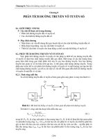
4 Data Transfer
The way data is transferred in RFID systems varies depending on application and type
of coupling. Close coupled and remote coupled systems have a magnetic couple to
one another through the mutual inductance M that allows rather unusual methods of
communication to be used. Long range systems on the other hand communicate on
distances too great to have enough mutual inductance between reader and tags for
these methods to be used. Other radio technologies are used instead for long range
systems.
4.1 Modulation
4.1.1 Load modulation
This is a modulation technique used only by close and remote coupled systems. The
technique makes use of the short distance between the reader and the transponder coil.
When the reader antenna coil generates a signal around its frequency fr the nearby
transponder is magnetically connected to the reader through its antenna coil. A current
is induced in the transponder coil. According to Lenz’s law the induced current tries
to counteract the field that induced it [19]. This effect is transferred to the reader
transmitter circuit via the mutual inductance M and can be measured as a voltage drop
over the antenna coil impedance. When the transponder circuit is loaded the voltage
drop is increased. This allows communication from the transponder back to the reader
by simply varying the load of the transponder circuit, see figure 4.1. Modulation of
the load can be accomplished both by a variable modulation resistance connected in
parallel with the load as well as with a variable modulation capacitor connected in
parallel with the load resistance. The two methods are referred to as ohmic load
modulation and capacitive load modulation. Ohmic load modulation in the
transponder generates amplitude modulation at the reader antenna branch while
capacitive load modulation in the transponder generates a combination of amplitude
and phase modulation at the receiver branch. The difference in phase at the reader
antenna when capacitive load modulation is applied arises from the transformed
transponder impedance. The voltage drop at the reader antenna arises when the
transponders impedance is transformed via the magnetic couple to the reader antenna
branch. A completely resistive impedance in the transponder will move only along the
real axis while capacitive transponder impedance makes a turn in the Smith chart
causing a change in value of both the real and the imaginary axis [1].
A widely used approach for systems in the frequency bands 6.78 MHz, 13.56 MHz
and 27.125 MHz is to first modulate a subcarrier with frequency fs, and then use the
subcarrier to modulate the main carrier with frequency fc. This results in a modulation
product, generating two sidebands symmetrically at the frequencies f c ± f s . The
modulation techniques for subcarrier modulation are amplitude shift keying (ASK),
frequency shift keying (FSK) and phase shift keying (PSK).
18