The control structure for DC motor based on the fl
Bạn đang xem bản rút gọn của tài liệu. Xem và tải ngay bản đầy đủ của tài liệu tại đây (689.94 KB, 8 trang )
International Journal of Power Electronics and Drive System (IJPEDS)
Vol. 8, No. 4, December 2017, pp. 1814~1821
ISSN: 2088-8694, DOI: 10.11591/ijpeds.v8i4.pp1814-1821
1814
The Control Structure for DC Motor based on the Flatness
Control
Thang Nguyen Trong
Departement of Industrial Electrical Engineering and Automation, Haiphong Private University, Vietnam
Article Info
ABSTRACT
Article history:
This article presents the new control structure for a Direct Current Motor
(DC Motor) using the flatness-control principle. Basic on the mathematical
model of DC Motors, the author demonstrates the application ability of the
fatness-control theory to control the DC Motor, and then calculates the
parameters and proposes the structure of the flatness-controller. The
proposed structure is built and ran on Matlab-Simulink software to verify the
system efficiency. The simulation results show that the quality of the control
system is very good, especially in case of the flatness controller combined
with PID controller to eliminate static error when the parameters of the DC
Motor have been not known accurately.
Received Sep 8, 2017
Revised Nov 23, 2017
Accepted Nov 30, 2017
Keyword:
Control structure
DC motor
Electric
Flatness cotroller
PID controller
Copyright © 2017 Institute of Advanced Engineering and Science.
All rights reserved.
Corresponding Author:
Thang Nguyen Trong,
Departement of Industrial Electrical Engineering and Automation,
Haiphong Private University,
36 Danlap street, Haiphong, Vietnam.
Email:
1.
INTRODUCTION
DC Motor is one of the traditional electric machines, is appeared in the late of 19th century. In
compared to the other electric machine such as induction machine [1], [2], brushless DC motors [3], the DC
Motor has the internal advantages such as simple control, large electromagnetic torque, the ability to adjust
the speed with the wide range [4]. So, DC Motors are still commonly used in industrial fields such as steel
rolling, transportation, mining, defense, construction [5-7]. Thus, improving the quality of DC Motor control
system is essential. There are many studies to control DC Motors [8-11], the most popular is still the method
using PID controllers. However, in many working modes of DC Motors, the nonlinear of DC Motor is high,
which reduces the quality of control system.
There are several solutions for controlling the nonlinear object such as the input-output linearization
method [12], the sliding mode control technique [13], the backstepping control technique [14], etc. The
drawback of the above methods is the existence of the chattering phenomenon or the difficult problem in the
choice of appropriate Lyapunov function. Therefore, the author proposes a suitable control system to improve
the control quality of a DC Motor, which is a control system based on flatness principle. With this method, it
is easy to decouple the input and output, directly identify each system variables by choosing the appropriate
system output variables.
The Flatness Control Theory is a new method control for nonlinear object [15], [16], promising a
high quality of control [17], being attracted by scientists around the world. Many researchers have come up
with different definitions of flatness control systems, but in general, the flatness control is regarded as a
useful tool for the nonlinear control system [18]. The most specific of the flatness system is the existence of
assemblage of z, through the z variables and the differential of the z variables, all state variables, and input
Journal homepage: />
IJPEDS
ISSN: 2088-8694
1815
variables can be determined. So we can determine in advance the trajectory of the input from the desired
trajectory of the output.
2. THE STRUCTURE CONTROL BASED ON FLATNESS CONTROL THEORY
2.1. The Basis of Flatness Control Theory
Flatness control theory is applied to control a lot of nonlinear objects which have the status equation
is written as follows [15], [19]:
x f ( x, u)
With
(1)
u (u1, u2 ,..um )T
is the input variables,
x ( x1 , x2 ,..xn )T
is the status variables.
The system (1) is called a flatness system if there are a set of variables
z ( z1, z2 ,..., zm )
called
the flat outputs, satisfying three conditions as follows:
a. Existing a function h, which is satisfied:
z h(x, u,...u( ) )
(2)
b. All input variables and state variables can be determined from the variable z, which means that
there are function A and function B, which are satisfied:
x A( z, z,...z ( ) )
(3)
u B( z, z,...z( 1) )
(4)
c. All variables of z are independently differential together, which means that there is not the
G( z, z,...z ) 0
function G, which is satisfied:
There are many control systems that satisfy the properties of flatness systems such as electric
motors, chemical reactors, cranes, transmission systems, eg.
( m)
2.2. Demonstrating the Flatness of DC Motors
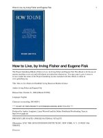
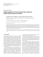
The structure of a separately excited DC Motor is shown in Figure 1, which includes:
a. The armature coil in the rotor
b. The excitation coil in the stator
Figure 1. The structure of the separately excited DC Motor
To demonstrate a DC Motor is flatness system, the first we have to definite the mathematical model
of the DC Motor, in order to prove DC Motor satisfies the conditions of the flatness system. The
mathematical equations of DC Motors are as follows:
a. The equation of voltage:
dia
E (V)
dt
With ua is the armature voltage;
ua Raia La
(5)
Ra , La is the armature resistance and inductance.
The Control Structure for DC Motor based on the Flatness Control (Thang Nguyen Trong)
1816
ISSN: 2088-8694
b. The equation of the Electromotive:
E K E (Laf .i f ).
(V)
(6)
With KE is the voltage coefficient, ω is the rotor speed,
if
Laf is the field armature mutual inductance,
is the field current.
c. The motion equation of the DC Motor:
J
d
T T B Tf (N.m)
dt e L m
Where
(7)
J is the inertia, Bm is the viscous friction coefficient, T f is the coulomb friction torque, Te
is the electromechanical torque, TL is the torque applied to the shaft.
d. The equation of electromechanical torque:
Te KT La (Laf .i f ).ia (N.m)
(8)
With KT is the torque coefficient.
From the equations of DC Motors, changing into the state equations with the state variables are the
armature current and the speed ( x (ia , ) , u
ua ):
Ra
KE
1
dia
dt L ia L L ua
a
a
a
d KT i Bm 1 T 1 T
J a J
J L J f
dt
(9)
Selecting the flat output variable is z , it is easy to prove that the DC Motor is flatness under
three conditions:
e. The first condition is existing the function h satisfied: z h( x, u,...u
Equation (9), it is easy to see that the first condition is satisfied.
( )
f. The second condition, there are the function A and the function B satisfied: x
).
From the
A(z, z,...z( ) ) ,
u B( z, z,...z ( 1) ) .
Transforming the Equation (9), we have:
ia
1
J Bm TL Tf K1 Jz Bm z TL Tf G1(z, z)
KT
T
So x (ia , )
(10)
A(, )
Transforming the Equation (9), we have:
Ra
J Bm TL Tf KLa (J. Bm TL ) KE
KT
E
Ra
La
Jz Bmz TL Tf K (J.z Bmz TL ) KE z G2(z, z, z)
KT
T
ua
So u ua
(11)
B( z, z, z)
So we can conclude that the second condition is satisfied
g. The third condition, all variables of z are independently differential together, this is obvious
because the flat outputs are selected with only one variable.
So we have concluded that DC Motors are flatness systems with flat output is z
IJPEDS Vol. 8, No. 4, December 2017 : 1814 – 1821
IJPEDS
ISSN: 2088-8694
1817
2.3. Designing the Flatness Controller
Based on the equations of DC Motors, we construct the stages of the flatness controller. From the
Equation (9), we design the speed controller (calculating the current ia ). From the Equation (9), we design
the current controller (calculating the voltage ua ).
The equation of speed controller:
ia*
1
KT
d*
J
Bm* TL Tf
dt
(12)
The equation of current controller:
ua Rai*a La
di *a
KE*
dt
(13)
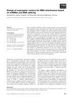
The block diagram of flatness control system for DC Motor is shown in Figure 2:
Figure 2. The block diagram of flatness control system for DC Motor
2.4. Building the Model Simulation
The control system diagram is constructed as shown in Figure 3.
Figure 3. The simulation n diagram of the control system with the flatness controller
In order to achieve objective results, in the diagram we use the DC Motor model available in the
Matlab-Simulink library, the parameters of DC Motor are shown in Table 1.
The Control Structure for DC Motor based on the Flatness Control (Thang Nguyen Trong)
1818
ISSN: 2088-8694
Table 1. The parameters of DC Motor
Ra()
0.5
La(H)
0.015
Rf()
220
Lf(H)
140
Laf(H)
1.7
J(kg.m^2)
1.2
Bm(N.m.s)
0.5
Tf(N.m)
20
Based on the model and parameters of DC Motor, the control block is built as follows:
a. The block of speed control is built based on the Equation (12), shown in Figure 4
b. The speed control block is built based on the Equation (13), shown in Figure 5.
Figure 4. The Speed Control Block
Figure 5. The Current Control Block
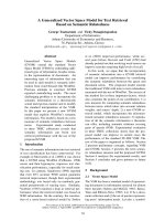
2.5. The Simulated Results
Running the system with the initial set speed 120(rad / s) , then changing the value of set
speed at time t = 1.5s and t = 3s ( 150(rad / s) and 180(rad / s) ). Load initially with the
torque of the shaft TL 50( N.m) , then at time t = 4.5(s) and t = 5.5(s), we increase TL to 100 (N.m) and
200 (N.m). The simulation results are shown in Figure 6(a). The simulation results show that the change of
speed values meet very good requirements.
For clarity, we study in more detail the graph of the set speed and actual speed in Figure (6b). From
the graph (6b), we see that the actual speed value is very close to the set speed value.
The change in speed depends on the load is shown in Figure (6c). Simulation results show that the
system is very high quality, the speed of the Motor is almost unchanged when the torque changes.
From the results above, we see that the proposed method with the simple control algorithm has the
high efficiency.
Figure 6. The simulated results with the flatness controller
IJPEDS Vol. 8, No. 4, December 2017 : 1814 – 1821
IJPEDS
ISSN: 2088-8694
1819
3.
THE PROBLEM OF THE PARAMETER ERROR OF THE MOTOR MODEL
The simulation results in part 2 show that the quality of the control system is perfect, because of the
assume that we know exactly the parameters of the DC Motor. However, in reality, it is impossible to know
the parameters of DC exactly, so the quality of control system is not perfect as above. To check the control
quality when DC parameter is not known exactly, we assume that some parameters of the DC Motor are
changed, the parameter of the DC Motor, after changed is shown in Table 2:
Table 2. The parameters of DC Motor after changed
Ra()
0.55
La(H)
0.016
Rf()
220
Lf(H)
145
Laf(H)
1.6
J(kg.m^2)
1.3
Bm(N.m.s)
0.6
Tf(N.m)
20
Running the system model, the response of the actual speed and set speed is shown in Figure 7. The
results show that there is a difference between the set speed and the actual speed. To eliminate this
difference, we add a PID controller connected in parallel with the flatness controller. The parallel control
diagram is shown in Figure 8. The simulation model with the additional PID controller is shown in Figure 9.
Figure 7. The simulated results when the DC parameter is not known exactly
Figure 8. The parallel control diagram
The Control Structure for DC Motor based on the Flatness Control (Thang Nguyen Trong)
1820
ISSN: 2088-8694
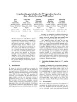
Figure 9. The simulation diagram of the control system with the additional PID controller
Running the model with the additional PID controller and Kp=3, Ki=0.5, the simulation results are
shown in Figure 10. The results show that when changing the set speed, the actual speed of DC Motor is very
close to the set speed, and when the torque of the shaft changes, the speed of DC Motor is not affected much.
So the flatness control system for DC Motor with the support of the PID controller has worked very well.
Figure 10. The simulated results with the additional PID controller
4.
CONCLUSION
In this paper, the author has successfully built the control system for DC Motor based on a flatness
control. The simulation results demonstrate that the system with the flatness controller works very well if we
know exactly the parameters of DC Motor. However, in fact, the parameters of the DC Motor have not
known accurately, so there is the error between set speed and actual speed when only the flatness control is
applied. A PID controller has been put into operation in parallel with the flat controller to eliminate their
error. The simulation results show that the quality of the whole system is very good and work effectively.
The actual speed of DC Motor is very close to the desired speed with the small transaction time. More, if the
load or the torque of the DC motor shaft is changed but the rotor speed of DC motor is not affected much.
Thus, the proposed system can be applied well in motion control applications that require the high-quality of
the speed control.
REFERENCES
[1]
Abdelhak, B., & Bachir, B., “A High gain observer based sensorless nonlinear control of induction machine,”
International Journal of Power Electronics and Drive Systems, 5(3), 305, 2015.
IJPEDS Vol. 8, No. 4, December 2017 : 1814 – 1821
IJPEDS
[2]
[3]
[4]
[5]
[6]
[7]
[8]
[9]
[10]
[11]
[12]
[13]
[14]
[15]
[16]
[17]
[18]
[19]
ISSN: 2088-8694
1821
Gunabalan, R., & Subbiah, V., “Speed Sensorless Vector Control of Induction Motor Drive with PI and Fuzzy
Controller,” International Journal of Power Electronics and Drive Systems, 5(3), 315, 2015.
Park, J. S., & Lee, K. D., “Design and Implementation of BLDC Motor with Integrated Drive
Circuit,” International Journal of Power Electronics and Drive Systems (IJPEDS), 8(3), 1109-1116, 2017.
Hughes, Austin, and Bill Drury, “Electric Motors and drives: fundamentals, types and applications,” Newnes,
2013.
Shieh, N. C., and P. C. Tung, "Robust output tracking control of a linear DC brushless Motor for transportation in
manufacturing system", IEE Proceedings-Electric Power Applications, 2001,pp. 119-124.
Pickrell, Don, and Paul Schimek, "Growth in Motor vehicle ownership and use: Evidence from the Nationwide
Personal Transportation Survey", Journal of Transportation and Statistics, vol.2.1, pp.1-17, 1999.
Fletcher, David I., and John H. Beynon, "Development of a machine for closely controlled rolling contact fatigue
and wear testing", Journal of testing and evaluation, Vol 28.4, pp. 267-275, 2000.
Bosco, Maycon Chimini, et al, "Estimation of parameters and tuning of a speed PI of permanent magnet DC Motor
using differential evolution", Electric Machines and Drives Conference (IEMDC), IEEE International,2017,pp.1-6.
Yao, Jianyong, Zongxia Jiao, and Dawei Ma, "Adaptive robust control of DC Motors with extended state observer",
IEEE Transactions on Industrial Electronics Vol 61.7 ,2014, pp. 3630-3637.
Xue, Dingyu, Chunna Zhao, and YangQuan Chen, "Fractional order PID control of a DC-Motor with elastic shaft:
a case study", American Control Conference, IEEE, 2006, pp.1-6
Thomas, Neenu, and Dr P. Poongodi, "Position control of DC Motor using genetic algorithm based PID
controller", Proceedings of the World Congress on Engineering, 2009, vol. 2, pp. 1-3.
Yazdanpanah, R., Soltani, J., & Markadeh, G. A., “Nonlinear torque and stator flux controller for induction motor
drive based on adaptive input–output feedback linearization and sliding mode control”, Energy Conversion and
management, 49(4), 541-550, 2008.
Abdelmadjid, G., Seghir, B. M., Ahmed, S., & Youcef, M., “Sensorless sliding mode vector control of induction
motor drives,” International Journal of Power Electronics and Drive Systems, 2(3), 277, 2012.
Trabelsi, R., Khedher, A., Mimouni, M. F., & M'sahli, F., “Backstepping control for an induction motor using an
adaptive sliding rotor-flux observer,” Electric Power Systems Research, 93, 1-15, 2012.
Martin, P., Murray, R. M., & Rouchon, P., “Flat systems, equivalence and trajectory generation,” 2003.
Xian-lin, C. H. E. N, "Flatness control in new generation high-tech mills for wide strip rolling", Journal of
University of Science and Technology Beijing, Vol 19, pp.1-5, 1997.
Jelali, Mohieddine, "Performance assessment of control systems in rolling mills–application to strip thickness and
flatness control", Journal of Process Control, Vol 17.10,pp. 805-816, 2007.
Farid, B., Waffa, B., & Bachir, B. A., “Flatness Based Nonlinear Sensorless Control of Induction Motor
Systems,” International Journal of Power Electronics and Drive Systems, 7(1), 265, 2016.
Delaleau, Emmanuel, and Aleksandar M. Stankovic, "Flatness-based hierarchical control of the PM synchronous
Motor", American Control Conference, Proceedings, Vol. 1, IEEE, 2004, pp. 65-70.
BIOGRAPHY OF AUTHOR
Thang Nguyen Trong received the B.Eng.degree in Automation Control from Hanoi University of
Science and Technology in 2005, and Ph.D.degrees in Control Engineering and Automation from
University of Transport and Communications, Vietnam in 2014. He is currently the Head of
Department of Industrial Electrical Engineering and Automation, Haiphong Privite University,
Vietnam. He is a member of Instittute of Electrical and Electronic Engineers (IEEE), his research
interests include automattion control theory, electric drive control, power generation systems on
ships.
The Control Structure for DC Motor based on the Flatness Control (Thang Nguyen Trong)