Effective method for detecting multi planes from depth maps
Bạn đang xem bản rút gọn của tài liệu. Xem và tải ngay bản đầy đủ của tài liệu tại đây (1.08 MB, 9 trang )
VNU Journal of Science: Natural Sciences and Technology, Vol. 33, No. 1 (2017) 58-66
Effective Method For Detecting Multi Planes
From Depth Maps
Dang Khanh Hoa1,*, Bach Ngoc Minh2, Nguyen Tien Dzung1
1
School of Electronics and Telecommunications, Hanoi University or Science and Technology,
1 Dai Co Viet, Hai Ba Trung, Hanoi, Vietnam
2
Vietnam National University, Hanoi, 144 Xuan Thuy, Cau Giay, Hanoi, Vietnam
Received 01 November 2016
Revised 15 December 2016; Accepted 23 March 2017
Abstract: In the field of visual stereo image processing, plane detection aims to assist in the
movement of the mobile vehicle or mobile robot. This paper has carried out the plane detection
problem based on depth map by using a new Neighbor Grouping algorithm and a rational Filter
(NGaF). The main advantage of this proposed method is the simplicity while it still ensures the
reliability of the results. A concise and clear hypothetical concept of the plane is built in the depth
map. Then the plane extracting algorithm is applied based on some strong characteristics of the
plane. The results of the applied method are considered positive in terms of both visual assessment
and evaluation parameter. Then, the NGaF approach is also be evaluated more superior than the
RANSAC algorithm, powerful PPDFDM and FPDIDM methods. The proposed method’s
computation time is reduced 33 times compared to the improved RANSAC algorithm (HSBSR).
Meanwhile, the result in number of found planes is greater than and PPDFDM, FPDIDM method
about 8% percentage. Last, the percentage of calculated valid points is larger than compared
methods 2%. It certainly has the ability to implement on common hardware with limited resources
as well as to ensure the real-time applications which processes stereo video signal.
Keywords: Detection, plane, depth map, depth difference, neighbor point.
1. Introduction
disparity map. In [1], the authors combine an
improved Hough transform with clustering to
search many targets in the image base on edge
of objects. These are able to detect multiple
objects with round shape or straight shapes.
However, the structure of extracted objects is
quite simply. So the applied algorithms could
not adapt for the natural environment in which
most thing is formed by planes. Work [2] has
an approach more realistically by solving the
problem of plane finding based on 3D Hough
transformation algorithm applied to 3D point
cloud. The major outstanding contribution is to
In the field of computer vision, plane
detection is one of basic applications in order to
mine visual data deeply including 3D
architectural
reconstruction,
and
robot
navigation. Recent studies show some
interesting results with difference algorithms.
These approachs also use many kind of input
such as 3D point cloud, single color image or
_______
Corresponding author. Tel.: 84-989123114.
Email:
58
D.K. Hoa et al. / VNU Journal of Science: Natural Sciences and Technology, Vol. 33, No. 1 (2017) 58-66
improve
the
complexity
of
Hough
transformation in the coordinate system of
three-dimensional space. The experienced
results are positive optimistic but it is clear that
the aim of real-time matching still is not met.
Manuscripts [3-5] present a new approach to
detect the planes by coordinating RANSAC
algorithm with MDL algorithm in order to
improve the reliability of the tested results.
There are some encouraging results on both
synthetic and real-world data. The method
could avoid detecting wrong planes due to the
complex geometry of the 3D data. But then the
complexity of the structure’s data is not taken
care. Even with the work [6], the horizontal
plane is detected from clues of vanishing points
of visual images or from the border detection of
3D point data. However, these methods are not
suitable for most types of building structures,
actually. The solution of the plane finding
presented in [7] bases on Particle Swarm
Optimization (PSO) with Region Growing (RG)
to extract small planes. It should need to discuss
more about the ability of reducing
computational costs and improving the
accuracy. The approaches mentioned above all
select the complex 3D input. Paper [8]
concentrates on a major step of VDEMs by
grouping of 3D point clouds optimally. So there
is a set of underlying surface which may
represent the into planar regions, whenever
possible. However, article [8] presents a
capable of plane extracting based on a disparity
map. This 2D input has a main advantage of
simplicity but it is easily taken large tolerances
in real scenes because the depth and the
disparity are not linearly proportional. The
authors have not addressed this difficulty
thoroughly in order to enhance the reliability of
the results
More recently, articles [9-11] refer to the
detection of any type of surface without camera
calibration by assuming a linear motion
cameras. The flat surfaces are parameterized by
transforming them into a parabola of c-velocity
space [9]. The author proposed a detection
method which exploits binding iso-velocity
59
curve after estimating an optical flow and
voting for the accumulations. C-velocity
function depends on two variables x and y with
the square root relationship so it is too high
complexity. The manuscript [11] presents some
fantastic results and they should be developed
further.
An interesting applied method [12-13]
could rapidly detect multi planes based on a
depth map obtained from the Kinect camera.
The applied algorithm calculates the local
normal vector of the group four adjacent points
in the depth map. Then process of coplanar
verification is implemented for each point in 3D
cloud data base on normal vector criteria. The
advantage of this method is able to detect
multiple planes simultaneously with improving
the speed of the plane detection process except
in [13]. Experimental results show that the rate
of proposed method is faster than some
previous methods such as 3D Hough
transformation algorithm and RANSAC
algorithm. It is also able to works in real time.
But besides that, the reliability of the results is
not as good as expected because the local
normal vectors are only calculated exactly in
case of the perfect depth map. This situation
rarely is met by a compact handset sensor cause
of its limited hardware resources. In addition,
the common prioritized aim is performing well
in real time.
In this manuscript, the proposed method
retains the advantages of the approaches [4, 5,
8] by introducing a simple hypothesis of the
plane concept in the depth map in order to
simplify the calculation more base on the same
input data. The rest of the paper is organized as
follows: Section 2 describes in detail
mathematical fundamentals, introducing stereo
camera system and some useful basic concepts.
In the third section, this work presents the
system architecture to perform searching of the
flat area as well as applied algorithms. The
fourth section is the obtained results and some
important discussions to improve outcomes in
different environments. The fifth section shows
several conclusions and the needed future work.
60
D.K. Hoa et al. / VNU Journal of Science: Natural Sciences and Technology, Vol. 33, No. 1 (2017) 58-66
2. Basic of planes mathematics and system
architecture
a) The basic mathematics of the plane in the
depth map
Mathematically, if a plane exists, it is a set
of adjacent consecutive points and satisfies an
represented plane equation defined as follows:
(1)
Ax By Cz D 0
Obviously, (1) has to satisfy the condition
A2 B 2 C 2 0 . From (1), z is drawn on a
side of the (1) and z becomes a function of two
variables x, y is written as follows:
A
B
D
(2)
x y
C
C
C
Taking partial derivatives of the function
(2) with respect to x variable and y variable
respectively:
z
z
A
x
C
(3)
z
B
y
C
(4)
Left
Camera
Right
Camera
Calibration
And
Rectify
Depth
Map
Fig. 1. The block diagram of stereo vision
camera system.
The distance T between the left camera
center OL and center of the right camera OR is
fixed. The line through the two center points of
cameras creates a baseline. PL and PR are the
projections of the object P in the left and the
right image respectively. Then xL and xR are
denoted horizontal coordinates of the
projections PL and PR
respectively. z is
indicated the depth of the object P in the frame
that is calculated based on the method of
triangular geometry (Fig. 2).
Thus, the gradient vector is defined:
z z A B
z , ,
x y C C
(5)
From (5), the depth gradient of a
predetermined plane is constant along with both
x axis and y axis directions. As such, the
adjacent points have the same depth gradient
values they belong to the same plane. This is a
reliable characteristic for the object in the
image is considered to be planar.
b) Maintaining the integrity of the specifications
Figure 1 illustrates the architecture of visual
stereo camera system which is modularization
of three function blocks. The first one consists
of two vision cameras these are installed
horizontally as same as a human eyes system.
The selection of these two cameras has to
ensure that they are identical to the focal length
f and other technical parameters.
Fig. 2. Principle of stereo vision.
The depth value z is calculated by the
following formula:
z
f .T
xL x R
(6)
c) Some of the basic concept
The depth map is one of the data outputs of
the stereo camera system, such as Microsoft's
Kinect device. Typically the depth map is
stored as a gray scale image with the value of
each point within range of 8-bit or 11-bit
representation. Each point p in a depth map has
D.K. Hoa et al. / VNU Journal of Science: Natural Sciences and Technology, Vol. 33, No. 1 (2017) 58-66
up to four neighboring points vertically and
horizontally which were named Top, Bottom,
Left, and Right corresponds to the position
relationship with p point shown in Fig. 3. Each
nearby point of p point will be considered as the
neighbor of p point if it meets the conditions of
depth differences with the central point that
must be less than a predetermined threshold θ.
A plane is structured by a set of pixels.
When a pixel is regarded as belonging to a
plane, the improbable event that it also lays on
a different flat surface. We could base on
mathematical and intuitive geometric to give
some properties of pixels of flat surface. A
pixel is said to be attached to a flat surface area
if it fully satisfies the following conditions:
Pixel must be adjacent to the considered
flat area.
61
will retain the trust planes which meet a set of
binding conditions.
Depth
mmap
Map
Enhancing
Neighbor
Grouping
Planes
Selection
Set of
Planes
Fig 4. Block diagram of plane detection system.
b) Map Enhancing
This study uses two sources of input data
corresponding to two different test cases. In the
first case, the implementation of the program on
nearly perfect data including disparity maps
from a library that shares across site
It is
not necessary to improve their quality (Fig. 5).
A pixel belongs to only one plane.
The depth disparity of the pixel is equal to
or less than an identified threshold.
Top
Left
p
Right
Bottom
Fig 3. Principle of stereo vision.
3. The system implementation
a) Architecture of processing system
The proposed NGaF system includes three
successive stages as shown in Fig. 4. The first
functional block is responsible for enhancing
the quality of depth image that it receives from
the Kinect. The main objective of this group is
to minimize noise in an image depth. The task
of the second function block is creating a set of
neighbors point groups with proposed Neighbor
Grouping algorithm. These groups are not
overlapping each other and the sum of all the
groups is smaller than the size of original depth
image. Each group will become a candidate for
selection by the last function block. This block
Fig 5. Illustration of data from Middlebury.
(a): Color Image; (b): Disparity map.
In the second test case, the process of
reducing the noise in input cannot be ignored.
The program collects depth data from
Microsoft’s Kinect sensor [14] (Fig. 6). Quality
of depth maps is usually not ideal (Fig. 7). The
appearing noise phenomenon occurs regularly
in each frame of the depth stream. The main
reason is the reflection of the uneven surface
caused by micro roughness structure. To
decrease this type of the noise, it is easy to see
that if a review of the scope of a window W is
small enough, they should always receive the
correct values and the variability of depth value
is not too strong. Thus, in the reviewed
window, if it contains some points with
unreasonable depth value then we can put them
on the average value of the actual value of the
points as shown in Fig. 7. The result is the
number of black points is greatly reduced. If the
62
D.K. Hoa et al. / VNU Journal of Science: Natural Sciences and Technology, Vol. 33, No. 1 (2017) 58-66
ratio between wrong value points and size of
window W is more than 50%, the repair work is
not effective because of lack of average value
information. However, if this work reference
experience from observing the actual depth
data, this kind of error mostly occurs in regions
which are far from the location of the camera.
So it has a less important role than the near
zone from camera’s position.
A Kinect streams out color, depth, and
skeleton data one frame at a time (Fig. 6). This
section briefly describes the coordinate spaces
for each data type and the API support for
transforming data from one space to another.
The APIs are designed to convert data from one
coordinate space to the other.
of center point pi less than or equal threshold
value θ will become a neighbor of pi (see
Section C, Part II.) And it is added to candidate
set Pk. One point that has been recognized as a
neighbor also has its neighbor points so it
should be considered as a central point later.
Each point is evaluated its relationship only
once with the role as a central point or as a
neighbor point. So after a point is concerned, it
will certainly be marked. The range of
threadhold θ is dependent on the quality of
input. If the program uses nearly perfect depth
maps it executes with fixed θ =1. Other cases,
the threadhold is get higher by 2. The algorithm
stops when the set S becomes empty.
Start
Initialize the set of points S
k=0
k ++ Initialize set of neighbor Pk = Φ
(a)
(b)
Fig 6. (a): Kinect’s Windows Sensor Components
and (b): Depth Space Range
Selection of pi in SPut pi into Pk
Considering of truth adjacent points of pi: top,
left, bottom, right
(a)
(b)
no
(c)
Fig 7. Illustration of captured data from Kinect and
improving result. (a): Color Image; (b): Depth map;
(c): Enhanced depth map.
c) Neighbor grouping
The task of this step is to provide set of the
candidates for the selection of worthy planes.
Each candidate including the points neighbors
that their order form connected planar area.
Assuming for a set of identified point S
includes points with its valid depth (Fig. 8).
Neighbors grouping algorithm starts with the
selection of center point pi in S and consider its
four nearby points. A nearby point that has a
depth value difference z from the depth value
z z
pi
z
adjacent
yes
Put the adjacent point into neighbor point set
Pk
yes
Select new of pi in Pk
no
S = S - Pk
no
S=Φ
yes
Stop
Fig. 8. Algorithm of neighbor grouping.
D.K. Hoa et al. / VNU Journal of Science: Natural Sciences and Technology, Vol. 33, No. 1 (2017) 58-66
d) Planes selection
The results of step 2 include groups that
each pair of points in which are neighbors each
other and they cover most valuable depth
points. Now, they can be considered as
candidates for voting planes. The task of this
step is to select the candidates that satisfy a
number of conditions in practice to generate a
real set of planes.
This leads to a common situation that we
might to accept. That's not all the elements of
the neighbor are planes. One of the important
filter conditions related to the minimum size of
the plane min. A candidate’s point number must
be greater than the determined minimum
threshold to ensure that a significant number of
small cluster interference is discarded
successfully. The minimum threshold min will
surely be affected in each case a specific scene,
so this program will experiment with some
different thresholds to check the number of the
flat zones and avoid skipping a few pieces of
planes in the set of real plane.
63
computing devices generally use some
algorithms with low complexity to achieve the
maximum gain in computation time. The
detected planes as illustrated in the last column
are shown to be smoothly matched with the real
scenes in both of two cases.
Color Image
Disparity Map
Planed Image
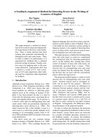
4. Experiences results and discussions
The program is written in C # tool in Visual
Studio 2012 environment, and implement on a
laptop with the configuration includes Core i52520 processor, maximum clocked 2.5Ghz,
Windows 7 Ultimate 64-bit SP1 (Fig. 10.).
In this section, the authors describe the
experimental results using the proposed
method. The experiment was conducted on two
different types of disparity map. The first input
data set consists of five disparity maps collected
from the common database with the link
/>as
illustrated in Fig. 9. The purpose of this test is
to implement the applied algorithm in case of
perfect disparity maps. To test the stability of
the proposed algorithm, the program is
executed with non-perfect depth maps as shown
in Fig. 11. This second case was happened
more frequently than the first case. Quality of
depth maps are not often ideal due to the depth
a)
b)
c)
Fig. 9. The results of the tested images in the plenty
of environment.
Note: a) color image, b) disparity maps, c) images with
the planes are marked in different colors. From top to
bottom, the first row is the Sawtooth image, the second
row is the Venus image, the third row is the Cones image,
the fourth is the Teddy image, and the last row is the
Books image, respectively;
Fig. 10. The practicing system for tested images.
D.K. Hoa et al. / VNU Journal of Science: Natural Sciences and Technology, Vol. 33, No. 1 (2017) 58-66
64
proposed method applying a filtering threshold
min=256. For Cones and Teddy pictures, result
of the FPDIDM algorithm corresponds to the
applied work with filtering threshold min=64.
The FPDIDM’s number of detected plane's in
Books corresponds to the applied method using
threshold min =128.
a)
b)
c)
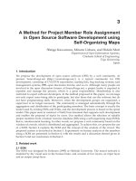
Fig. 11. The results of the tested images capturing
from Microsoft’s Kinect sensor.
Figure 13 demonstrates the number of the
detected planes with the minimum threshold
min from 32 to 256 with depth maps from the
Kinect. Obviously, as well as Fig.12, the
threadhold min is greater the number of
detected planes is less because of some plane
pieces such as spot noises were discarded. The
reduction rate of quantity plane is near 50%
while min jumps from 32 to 64 and from 64 to
128 but this reduction rate keeps small when
the minimum threshold increased from 128 to
256 in all tested cases. Also the number of
detected planes depends on the objects in the
scenes greatly.
Note: a) color images, b) depth maps, c) images with the
planes are marked in different colors. From top to bottom,
the first row is the Non Obstacle image, 1- Obstacle image, 2Obstacle image and 3- Obstacle image, respectively;
m in=32
m in=64
m in=128
200
180
160
149
122
120
106
Fig. 3.
100
80
40
20
FP DIDM [8]
181
Fig. 2.
140
60
m in=256
Fig. 1.
77
73
Fig. 4.
36
23 13
9
4 33
Sa wto o th
7
5
Ve nus
76
72
52
36
24
28
Fig. 6.C o ne s
Te ddy
5Fig.
62 63
42
5.
B o o ks
Fig. 13. The number of detected planes according to
some difference minimum thresholds min with depth
maps from Kinect.
Fig. 12. Comparisions between the number of
detected planes according to some difference
minimum thresholds min and FPDIDM method [8]
for disparity maps from Midlebury library.
Figure 12 shows a comparison of the
number of planes detected between the applied
approach and FPDIDM method [8]. For
Sawtooth and Venus images, the results of the
FPDIDM method corresponds to result of the
(a)
(b)
(c)
D.K. Hoa et al. / VNU Journal of Science: Natural Sciences and Technology, Vol. 33, No. 1 (2017) 58-66
65
5. Conclusions
(d)
(e)
(f)
Fig. 14. The results of HSBSR [4], PPDFDM [5],
FPDIDM [8] methods and the proposed algorithm
on Toulouse’s St-Michel Jail disparity map.
Note: (a): reference image, (b): disparity map, (c):
Planar patch classification of [4], (d): Planar patch
classification of [5], (e): Planar patch classification of
FPDIDM [8] method. Each gray level corresponds to a
different plane. The red parts are defined as non
planar according to the validation theory of [4], (f):
Planar patch classification of proposed method. Each
color corresponds to a different plane.
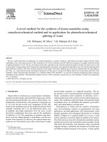
Figure 15, 14 illustrate a comparison among
the proposed method and three others approachs
consisting HSBSR, PPDFM, FPDIDM. The
experienced results is evaluated on three
common parameters including the computation
time, the number of planes detected and
percentage rate of valid points (Fig. 15).
Processing time of proposed approach is lowest.
Even the proposed method’s computation time
is reduced 33 times compared to the improved
RANSAC algorithm (HSBSR). Meanwhile, the
result in number of found planes is greater than
and PPDFDM, FPDIDM method about 8%
percentage. Last, the our results in percentage
rate valid point is better than others approach
2% at least.
HSBSR
PPDFDM
FPDIDM
103
89 92
100
98
Our method
91
93 92 95
80
60
50
40
20
4
9
1.5
Computation tim e (s)
Number of planes
Valid point (%)
Fig. 15. Comparisons of three parameters among
HSBSR, PPDFDM, FPDIDM and the proposed
approach on Toulouse’s St-Michel Jail
disparity map.
In this work, we proposed a Neighbor
Grouping and Filtering (NGaF) algorithm to
detect the planar and semi-planar surfaces from
only one depth map or disparity map. This
manuscript shows a various of tested results
which demonstrate the robust proposed method.
By comparing of three common parameters
among interesting methods, the applied
algorithm illustrates a high performance
certainly. In future work, this project should be
improved by using real-time depth video.
Acknowledgments
Many thanks to School of Electronics and
Telecommunications (SET), Hanoi University
of Science and Technology (HUST) for kindly
funding this article through scientific research
project that named “Research and development
of ground planes and obstacles extracting
algorithms based on the Kinect sensor system
for supporting mobile robot navigation
applications” with code T2016-PC-108.
References
[1] Fei Rong, Cui Duwu, “A Novel Hough
Transform Algorithm for Multi-objective
Detection”, 2009 Third International Symposium
on
Intelligent
Information
Technology
Application, pp. 705-708.
[2] Borrmann, Dorit, et al. "The 3D Hough
Transform for plane detection in point clouds: A
review and a new accumulator design." 3D
Research 2.2, 2011, pp. 1-13.
[3] Yang, Michael Ying, and Wolfgang Förstner.
"Plane detection in point cloud data."
Proceedings of the 2nd int conf on machine
control guidance, Bonn. Vol. 1.2010, pp. 95-104.
[4] Labatut, Patrick, Jean-Philippe Pons, and
Renaud Keriven. "Hierarchical shape-based
surface reconstruction for dense multi-view
stereo." Computer Vision Workshops (ICCV
Workshops), 2009 IEEE 12th International
Conference on. IEEE, 2009, pp. 1598-1605.
66
D.K. Hoa et al. / VNU Journal of Science: Natural Sciences and Technology, Vol. 33, No. 1 (2017) 58-66
[5] Bughin, Eric, and Andrés Almansa. "Planar
Patch Detection for Disparity Maps." Proc.
3DPVT. 2010.
[6] Zhang, Meng, et al. "Horizontal plane detection
from 3D point clouds of buildings." Electronics
letters 48.13, 2012, pp. 764-765.
[7] Hiroyuki Masuta, Shinichiro Makino, Hun-ok
Lim, “3D plane detection for robot perception
applying particle swarm optimization”, 3-7 Aug,
2014 World Automation Congress (WAC), pp.
549 - 554.
[8] E. Bughin, A. Almansa, R. Grompone von Gioi, Y.
Tendero, “Fast Plane Detection In Disparity Maps”,
Proceedings of 2010 IEEE 17th International
Conference on Image Processing, September 26-29,
2010, Hong Kong, pg. 2961- 2964.
[9] Bouchafa, Samia, Antoine Patri, and Bertrand
Zavidovique. "Efficient plane detection from a
single moving camera." 2009 16th IEEE
International Conference on Image Processing
(ICIP). IEEE, 2009, pp. 3493-3496.
[10] Haines, Osian, and Andrew Calway. "Detecting
planes and estimating their orientation from a
single image." BMVC, 2012, pp. 1-11.
[11] Deschaud, Jean-Emmanuel, and François
Goulette. "A fast and accurate plane detection
algorithm for large noisy point clouds using
filtered normals and voxel growing."
Proceedings of 3D Processing, Visualization and
Transmission Conference (3DPVT2010), Paris,
France, 2010.
[12] Hyun Woo Yoo, Woo Hyun Kim, Jeong Woo
Park, Won Hyong Lee and Myung Jin Chung,
"Real-time plane detection based on depth map
from Kinect," Robotics (ISR), 2013 44th
International Symposium on, Seoul, 2013, pp. 1-4.
[13] Fouhey, David F., Daniel Scharstein, and Amy J.
Briggs. "Multiple plane detection in image pairs
using j-linkage." Pattern Recognition (ICPR),
2010 20th International Conference on. IEEE,
2010, pp. 336-339.
[14] Microsoft, />ary/jj131033.aspx
Phương pháp hiệu quả phát hiện đa mặt phẳng từ bản đồ độ sâu
Đặng Khánh Hòa1, Bạch Ngọc Minh2, Nguyễn Tiến Dũng1
1
Viện Điện tử Viễn thông, Đại học Bách Khoa,
Số 1 Đại Cồ Việt, Hai Bà Trưng, Hà Nội, Việt Nam
2
Đại học Quốc gia Hà Nội, 144 Xuân Thủy, Cầu Giấy, Hà Nội, Việt Nam
Tóm tắt: Trong lĩnh vực xử lý hình ảnh thị giác stereo, phát hiện mặt phẳng nhằm mục đích hỗ
trợ sự di chuyển của phương tiện giao thông hay robot di động. Bài viết này thực hiện giải quyết vấn
đề phát hiện mặt phẳng dựa trên bản đồ độ sâu bằng cách sử dụng một thuật toán phân nhóm hàng
xóm mới và bộ lọc hợp lý (NGaF). Ưu điểm chính của phương pháp đề xuất này là sự đơn giản trong
khi vẫn đảm bảo độ tin cậy của các kết quả. Đầu tiên, một giả thuyết về mặt phẳng trong các bản đồ
độ sâu được xây dựng ngắn gọn và rõ ràng. Sau đó các thuật toán trích mặt phẳng được áp dụng dựa
trên một số đặc trưng chắc chắn của mặt phẳng. Kết quả của phương pháp áp dụng được đánh giá là
tích cực trên cả hai mặt trực quan và qua các thông số quan trọng. Phương pháp tiếp cận NGaF cũng
đang được đánh giá vượt trội hơn so với các phương pháp sử dụng thuật toán kinh điển RANSAC,
thuật toán mạnh PPDFDM và FPDIDM. Thời gian tính toán của phương án đề xuất giảm 33 lần so
với các thuật toán RANSAC được cải thiện (HSBSR). Trong khi đó, số lượng mặt phẳng được tìm
thấy là lớn hơn khoảng 8% so với kết quả của phương pháp PPDFDM và FPDIDM. Cuối cùng, tỷ lệ
phần trăm các điểm có giá trị được xử lý lớn hơn 2% so với các phương pháp được so sánh. Phương
pháp đề xuất chắc chắn có khả năng thực hiện trên phần cứng thông thường với nguồn lực hạn chế
cũng như đảm bảo cho các ứng dụng thời gian thực về xử lý tín hiệu video.
Từ khóa: Mặt phẳng, phát hiện, bản đồ độ sâu, sự khác biệt độ sâu, điểm hàng xóm.