Plasmonic thin film InP/graphene-based Schottky-junction solar cell using nanorods
Bạn đang xem bản rút gọn của tài liệu. Xem và tải ngay bản đầy đủ của tài liệu tại đây (1.32 MB, 6 trang )
Journal of Advanced Research 10 (2018) 15–20
Contents lists available at ScienceDirect
Journal of Advanced Research
journal homepage: www.elsevier.com/locate/jare
Original Article
Plasmonic thin film InP/graphene-based Schottky-junction solar cell
using nanorods
Abedin Nematpour a, Mahmoud Nikoufard b,⇑
a
b
Department of Nanoelectronics, Nanoscience and nanotechnology Research Center, University of Kashan, Kashan, Iran
Department of Electronics, Faculty of Electrical and Computer Engineering, University of Kashan, Kashan 87317-51167, Iran
g r a p h i c a l a b s t r a c t
a r t i c l e
i n f o
Article history:
Received 20 September 2017
Revised 4 January 2018
Accepted 24 January 2018
Available online 4 February 2018
Keywords:
Graphene/InP solar cells
Nanorods
Graphene
Light trapping
Short circuit current density
Finite difference method (FDM)
a b s t r a c t
Herein, the design and simulation of graphene/InP thin film solar cells with a novel periodic array of
nanorods and plasmonic back-reflectors of the nano-semi sphere was proposed. In this structure, a
single-layer of the graphene sheet was placed on the vertical nanorods of InP to form a Schottky junction.
The electromagnetic field was determined using solving three-dimensional Maxwell’s equations discretized by the finite difference method (FDM). The enhancement of light trapping in the absorbing layer
was illustrated, thereby increasing the short circuit current to a maximum value of 31.57 mA/cm2 with
nanorods having a radius of 400 nm, height of 1250 nm, and nano-semi sphere radius of 50 nm, under
a solar irradiation of AM1.5G. The maximum ultimate efficiency was determined to be 45.8% for an angle
of incidence of 60°. This structure has shown a very good light trapping ability when graphene and ITO
layers were used at the top and as a back-reflector in the proposed photonic crystal structure of the InP
nanorods. Thence, this structure improves the short-circuit current density and the ultimate efficiency of
12% and 2.7%, respectively, in comparison with the InP-nanowire solar cells.
Ó 2018 Production and hosting by Elsevier B.V. on behalf of Cairo University. This is an open access article
under the CC BY-NC-ND license ( />
Peer review under responsibility of Cairo University.
⇑ Corresponding author.
E-mail address: (M. Nikoufard).
/>2090-1232/Ó 2018 Production and hosting by Elsevier B.V. on behalf of Cairo University.
This is an open access article under the CC BY-NC-ND license ( />
16
A. Nematpour, M. Nikoufard / Journal of Advanced Research 10 (2018) 15–20
Introduction
Solar cells, which convert solar energy into electrical energy
with remarkable conversion efficiencies, are attractive candidates
for renewable [1], endless and clean power sources [2,3]. Meanwhile, thin solar cells are a very important class of photovoltaics
and have recently become the subject of intense research, commercialization, and development efforts due to their high efficiency and low cost. Commonly, the film thickness is equivalent
to two microns or less, and is used in absorptive materials devices
[4]. Light trapping is one of the methods of increasing light absorption in thin film solar cells, due to multiple reflection within the
absorbing layers [5–7]. Light-trapping can be achieved by the formation of a wavelength-scale texture on the substrate and by
depositing thin layers of the solar cell on it [8]. Compared with
the generally used Si, indium phosphide (InP) has a direct band
gap of 1.34 eV [9,10], which is located in the broad range of the
solar energy spectrum [11]. InP solar cells are very desirable as
space solar cells [12]. Graphene is the first substance discovered
with a 2D atomic crystal [13,14], having a honeycomb lattice structure. Graphene has a high carrier mobility [15], remarkable conductivity, and transparency [11]. It has great potentials for
applications in the making of novel optoelectronic and electronic
devices [16–20]. As a result of its special characteristics, graphene
is an ideal electrode for use in thin solar film cells [11]. The
graphene-semiconductor Schottky junction offers a new platform
for photovoltaic devices. A Schottky junction is created if the work
function difference between the metal and the semiconductor is
large enough and the semiconductor carrier density is moderate
or low [1]. In addition, the fabrication of Schottky junctions has
the benefit of low-cost and simplicity [2].
Recently, Schottky junction solar cells have been made with a
single layer of graphene on Si substrate, so that graphene behaves
as a metal [21]. Graphene-based Schottky junction solar cells have
been displayed on various substrates such as CdS [22], CdSe [22], Si
[22] and InP [11] with power conversion efficiencies ranging from
0.1 up to 2.86%. Miao et al. [22] demonstrated a power conversion
efficiency of 8.6% for a doped graphene/nASi Schottky junction
solar cell. Shi et al. [21] have shown a TiO2-G-Si solar cell showed
excellent device parameters including an open-circuit voltage of
0.612 V, a fill factor of 72%, and an incident photon to electron conversion efficiency of up to 90% across the visible spectrum. Wang
et al. [11] demonstrated a graphene/thin film InP Schottky junction. The proposed solar cell was shown power conversion efficiency of 3.3% [11].
In this article, a novel InP-based graphene-Schottky junction
solar cell, composed of InP-nanorods is proposed. A thin layer of
silver is deposited on one side of the nanorods with the semispherical surface serving as a back-reflector with a single layer of graphene on top of the InP nanorods, to improve the optical
properties of the proposed solar cell. The indium tin oxide (ITO)
and graphene layers on top of the nanorods and silver layer on
the bottom of the solar cell structure form an optical waveguide
which facilitates light trapping. The proposed solar cell architecture increases the light absorption, the short-circuit current density and the ultimate efficiency overall incident wavelengths in
the solar spectrum from 400 to 920 nm.
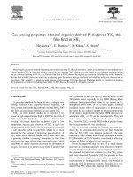
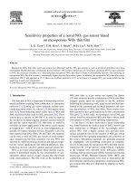
gle layer of the graphene sheet, an anti-reflective layer of ITO on
top of a graphene layer with the thickness of h2. The edge-toedge distance between the nanorods of InP is equal to d.
To obtain a realistic solar cell performance, the spectrum of AM
1.5G is utilized to determine the wavelength dependent absorption
(A(k)) over the sunlight electromagnetic spectrum. The relation
between the incident power, Pin (k), output power, Pout (k), and A
(k) are given as [23]:
AðkÞ ¼
Pin ðkÞ À Pout ðkÞ
Pin ðkÞ
ð1Þ
This helps to calculate the weighted absorption of < Aw> within
the wavelength range of k1 and k2 [24–26]:
R k2
hAw i ¼
AðkÞwðkÞdk
R k2
wðkÞdk
k1
k1
ð2Þ
Here, w(k) is the incidence solar flux per unit wavelength and
k1=400 nm and k2 = 920 nm (k2 = 920 nm-corresponding to the
band edge for InP) are assumed. Short-circuit current density (Jsc)
can also be calculated [27] as
J SC ¼
e
hc
Z
k2
k1
kAðkÞwðkÞdk
ð3Þ
Wherever h, c, and e are the Planck constant, the speed of light in
vacuum space and the electron charge density, respectively. The
short circuit current is proportional to the number of incident photons at the top of the bandgap; it is considered that all photons are
absorbed to generate the electron-hole pairs and each photogenerated carrier can reach the electrodes [28–30]. The finite difference method (FDM) is used to determine the electromagnetic fields
(optical fields) propagated through the structure. In this method,
Maxwell’s equations are discretized in the solar cell structure.
To evaluate the optical absorption performance of the photovoltaic, the ultimate efficiency (g) is calculated, which is described
as the efficiency of the solar cell as the temperature approaches 0
K, when each photon with energy higher than the bandgap energy
generates an electron-hole pair [31,32].
g¼
2phAQ s
kg
P in
ð4Þ
Material and methods
The layer stack of the graphene-InP Schottky junction solar cell
is shown in Fig. 1. This structure is periodic in the x and y directions. The specifications of layers are Indium phosphide (InP)
nanorods with a height of h1 and a radius of R1, nano-semi sphere
silver with a radius of R2 grown on a silver-coated substrate, a sin-
Fig. 1. Three dimensional (3D) schematics view of the InP-based graphene Schottky
junction solar cell.
A. Nematpour, M. Nikoufard / Journal of Advanced Research 10 (2018) 15–20
R kg
g¼
0
AðkÞwðkÞ kkg dk
R kg
wðkÞdk
0
ð5Þ
Which kg and Q s are the wavelength corresponding to the bandgap
wavelength of absorption layer and the number of quanta of wavelength shorter than kg incident per unit area per unit time.
Results and discussion
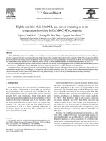
In the wavelength range between 400 and 920 nm, the normalized absorption A(k) as a function of wavelength is shown in Fig. 2,
for different radii of InP nanorods. By increasing the radius of
nanorods from 200 to 500 nm, the optical absorption of the proposed structure can be greatly enhanced at the IR (Infrared
Radiation)-wavelength. The use of a silver nano-semi sphere as a
back reflector creates localized surface plasmons on the silver
nano-structures. Thus, under appropriate conditions, this structure
effectively reflects the incident optical power.
The thickness of the anti-reflection coating layer of ITO must
satisfy the relation h2 = k/4n, where k and n are the wavelength
and refractive index of the anti-reflection coating layer, respectively. The thickness of ITO was determined as 65 nm at a wave-
Fig. 2. Absorption as a function of wavelength for different radius of InP nanorods
(R2 = 50 nm, d = 100 nm, h1 = 1000 nm, and h2 = 65 nm).
17
length of 510 nm with a reflective index of 1.93. By considering
the nano-semi sphere radius of 50 nm, the distance between adjacent nanorods of 100 nm, and height of nanorods of 1000 nm, the
weighted absorption as a function of the radius of nanorods determined is shown in Fig. 3(a). Meanwhile, the short-circuit current
density as a function of the radius of nanorods is depicted in
Fig. 3(b). The maximum value of the short current circuit and the
weighted absorption was obtained at a radius of about R1 = 400
nm, due to the maximum reflectance at the nanorod/air interface.
As can be observed in Fig. 3, the absorbed optical power increased
with increase in the radius of the nanorods (R1 < 400 nm) because
more optical power entered the InP-nanorods. For the radius of
nanorods higher than 400 nm, the trapped optical power became
reduced as a result of the decrease in the path length of the
reflected optical power.
Another variable parameter for increasing the trapping of light
in this structure is the distance between the InP nanorods (d). The
gap between the nanorods is changed from 50 to 200 nm to determine the absorption and short-circuit current density (see Fig. 4)
by assuming R1 = 400 nm and h1 = 1000 nm while the remaining
parameters are kept constant. Fig. 4 is shown that the maximum
values of the short circuit current density of 31 mA/cm2 and the
weighted absorption of 0.92, occurred at a distance of 75 nm
between nanorods. It can be observed that the guiding light
decreases within the InP-nanorods as the gap between the nanorods increases in the solar cell structure. By increasing the gap
between the InP nanorods, the spatial distribution density of InPnanorods decreased and consequently, light trapping reduced in
the InP nanorods.
In the next step, the weighted absorption and short-circuit current density were also determined for the various heights of InP
nanorods while R1 = 400 nm and d = 75 nm were kept constant.
The maximum short circuit current density of 31.36 mA/cm2 was
obtained at h1 = 1250 nm. By increasing the height of the InP
nanorods above 1250 nm (h1 = 1250 nm), the weighted absorption
and the short-circuit current became reduced because less optical
power reached the nano-semi sphere and was reflected back, thus
reducing the light trapping (see Fig. 5(a) and (b)). The weighted
absorption of the solar cell without the nano-semi sphere was also
determined for the various heights of InP nanorods which causes
less light trapping (Fig. 5(a)). Also, the extinction spectrum of the
plasmonic nano-semi sphere (defined as the sum of absorption
cross-section and scattering cross-section) is shown in Fig. 5(c)
and is in good agreement with Fig. 5(a) and (b).
The angle of incidence on the solar cell plays an important role
in light trapping to have a maximum propagation length inside the
Fig. 3. (a) Weighted absorption hAwi and (b) short current circuit density (Jsc) as a function of R1 (R2 = 50 nm, d = 100 nm, h1 = 1000 nm, and h2 = 65 nm).
18
A. Nematpour, M. Nikoufard / Journal of Advanced Research 10 (2018) 15–20
Fig. 4. (a) Weighted absorption hAwi and (b) short circuit current density (Jsc) versus d (R2 = 50 nm, R1 = 400 nm, h1 = 1000 nm, and h2 = 65 nm).
structure. Fig. 6 is shown the short circuit current density (JSc) for
different angles of incidence of the incoming light for R1 = 400 nm,
d = 75 nm, and h1 = 1250 nm. The short circuit current density
reaches a minimum value at an angle of 30° with respect to the
normal incidence and then increases at an incident angle of 60°
(JSC = 31.57 mA/cm2). The scattered light has a maximum propagation length through the solar cell structure at the angle of 60°,
results in maximum light trapping, while it reaches to a minim
value at the angle of 30°.
Ultimate efficiency is the best estimate of the optical performance of the solar cell. Ultimate efficiency was calculated for different angles of incidence of the incoming light for R1 = 400 nm,
d = 75 nm, and h1 = 1250 nm (see Fig. 7). It was observed that the
maximum value of ultimate efficiency is 45.8% at an incident angle
of 60°.
In the design of thin film solar cells, light trapping is important,
so as to increase light absorption. Light trapping occurs due to the
presence of ITO and graphene on top and silver at the bottom of the
structure. Also, the nanorod photonic crystal structure and plasmonic back-reflectors are an attractive solution to the light trapping of long wavelength photons leading to enhanced light
absorption in the periodically structured device. The structure of
the anti-reflection coating surface (ITO) is very effective in repressing reflection loss, for example, short circuit current density is with
and without the use of ITO 31.57 mA/cm2 and 29.43 mA/cm2 for an
incident angle of 60°, R1 = 400 nm, d = 75 nm, and h1 = 1250 nm.
Fig. 5. (a) Weighted absorption hAwi, (b) short circuit current density (Jsc) as a function of h1 (R2 = 50 nm, R1 = 400 nm, d = 75 nm, and h2 = 65 nm), and (c) the extinction
spectra of plasmonic nano-semi sphere.
A. Nematpour, M. Nikoufard / Journal of Advanced Research 10 (2018) 15–20
19
Poynting vector on the graphene surface is shown through all
angles, thereby increasing the path length of photons within the
absorber layer. The graphene-InP interface enhances the surface
reflectivity.
The main advantage of the proposed solar cell in respect to the
InP-based nanowire [12,33,34] (without a back-reflector and graphene layers) is higher than the short-circuit current density and
the ultimate efficiency of 3.37 mA/cm2 and 2.7%, respectively.
Conclusions
Fig. 6. Short circuit current density (Jsc) against different angles of incidence of the
incoming light (R2 = 50 nm, R1 = 400 nm, d = 75 nm, h1 = 1250 nm, and h2 = 65 nm).
In this paper, a novel graphene/InP Schottky junction solar cell
with a periodic array of nanorods with a back-reflector of nanosemi sphere silver and using an ITO layer of the anti-reflection
coating was simulated. 3D simulations were based on a finite difference method (FDM) to determine absorption, the weighted
absorption, the short-circuit current, and ultimate efficiency. It
was found that an optimized geometry with R1 = 400 nm, d = 75
nm, h1 = 1250 nm, R2 = 50 nm and an incident angle of 60° would
absorb 400 nm up to 920 nm wavelength of sunlight, obtaining
the short-circuit current density and the ultimate efficiency of
31.57 mA/cm2 and 45.8%, respectively. Therefore, this design
demonstrates a considerable reduction in absorbing layer thickness with respect to the planar InP-based solar cell.
Conflict of interest
The authors have declared no conflict of interest.
Compliance with Ethics Requirements
This article does not contain any studies with human or animal
subjects.
Fig. 7. The ultimate efficiency for different angles of incidence of the incoming light
(R2 = 50 nm, R1 = 400 nm, d = 75 nm, h1 = 1250 nm, and h2 = 65 nm).
Fig. 8. Poynting vector in the surface of graphene (R2 = 50 nm, R1 = 400 nm, d = 75
nm, h1 = 1000 nm and h2 = 65 nm).
Therefore, after coating ITO, the solar cell has shown a muchreduced light reflection in the same wavelength spectrum.
The lateral propagation of the wave on the graphene surface can
be observed in the Poynting vector plot as shown in Fig. 8. The
References
[1] Nayebi P, Emami-Razavi M, Zaminpayma E. Electronic and optical properties of
CuGaS2 nanowires: a study of first principle calculations. Eur Phys J B 2017;90
(1):11.
[2] Ye Y, Dai Y, Dai L, Shi Z, Liu N, Wang F, et al. High-performance single CdS
nanowire (nanobelt) Schottky junction solar cells with Au/graphene Schottky
electrodes. ACS Appl Mater Interfaces 2010;2(12):3406–10.
[3] Safarian S, Khodaparast P, Kateb M. Modeling and technical-economic
optimization of electricity supply network by three photovoltaic systems. J
Sol Energy Eng 2014;136(2):024501.
[4] Hilali MM, Sreenivasan SV. Nanostructured silicon-based photovoltaic cells. In:
Wang X, Zhiming M, editors. High efficiency solar cell. London: Springer; 2014.
p. 131–64.
[5] Cai T, Han SE. Effect of symmetry in periodic nanostructures on light trapping
in thin film solar cells. JOSA B 2015;32(11):2264–70.
[6] Nayebi P, Emami-Razavi M, Zaminpayma E. Study of electronic and optical
properties of CuInSe2 nanowires. J Phys Chem C 2016;120(8):4589–95.
[7] Das S, Kundu A, Saha H, Datta SK. Enhanced optical absorption and electrical
performance of silicon solar cells due to embedding of dielectric nanoparticles
and voids in the active absorber region. J Mod Opt 2013;60(7):556–68.
[8] Catchpole K, Polman A. Plasmonic solar cells. Opt Express 2008;16
(26):21793–800.
[9] Ghosh D, Ghosh B, Hussain S, Chakraborty B, Sehgal G, Bhar R, et al.
Improvement on the performance of InP/CdS solar cells with the inclusion of
plasmonic layer of silver nanoparticles. Plasmonics 2014;9(6):1271–81.
[10] Walters RJ, Messenger S, Summers G, Romero M, Al-Jassim M, Araújo D, et al.
Radiation response of n-type base InP solar cells. J Appl Phys 2001;90
(7):3558–65.
[11] Wang P, Li X, Xu Z, Wu Z, Zhang S, Xu W, et al. Tunable graphene/indium
phosphide heterostructure solar cells. Nano Energy 2015;13:509–17.
[12] Wallentin J, Anttu N, Asoli D, Huffman M, Åberg I, Magnusson MH, et al. InP
nanowire array solar cells achieving 13.8% efficiency by exceeding the ray
optics limit. Science 2013;339(6123):1057–60.
[13] Zoghi M, Goharrizi AY, Saremi M. Band gap tuning of armchair graphene
nanoribbons by using antidotes. J Electron Mater 2017;46(1):340–6.
[14] Lashgari H, Boochani A, Shekaari A, Solaymani S, Sartipi E, Mendi RT. Electronic
and optical properties of 2D graphene-like ZnS: DFT calculations. Appl Surf Sci
2016;369:76–81.
20
A. Nematpour, M. Nikoufard / Journal of Advanced Research 10 (2018) 15–20
[15] Goharrizi AY, Zoghi M, Saremi M. Armchair graphene nanoribbon resonant
tunneling diodes using antidote and BN doping. IEEE Trans Electron Devices
2016;63(9):3761–8.
[16] Britnell L, Gorbachev R, Geim A, Ponomarenko L, Mishchenko A, Greenaway M,
et al. Resonant tunnelling and negative differential conductance in graphene
transistors. Nat Commun 2013;4:1794.
[17] Wu W, Wang L, Li Y, Zhang F, Lin L, Niu S, et al. Piezoelectricity of singleatomic-layer MoS2 for energy conversion and piezotronics. Nature 2014;514
(7523):470–4.
[18] Baugher BW, Churchill HO, Yang Y, Jarillo-Herrero P. Optoelectronic devices
based on electrically tunable pn diodes in a monolayer dichalcogenide. Nat
Nanotechnol 2014;9(4):262–7.
[19] Lopez-Sanchez O, Lembke D, Kayci M, Radenovic A, Kis A. Ultrasensitive
photodetectors based on monolayer MoS2. Nat Nanotechnol 2013;8
(7):497–501.
[20] Zheng C, Zhang Q, Weber B, Ilatikhameneh H, Chen F, Sahasrabudhe H, et al.
Direct observation of 2D electrostatics and ohmic contacts in template-grown
graphene/WS2 heterostructures. ACS Nano 2017;11(3):2785–93.
[21] Shi E, Li H, Yang L, Zhang L, Li Z, Li P, et al. Colloidal antireflection coating
improves graphene–silicon solar cells. Nano Lett 2013;13(4):1776–81.
[22] Miao X, Tongay S, Petterson MK, Berke K, Rinzler AG, Appleton BR, et al. High
efficiency graphene solar cells by chemical doping. Nano Lett 2012;12
(6):2745–50.
[23] Gwamuri J, Güney D, Pearce J. Advances in plasmonic light trapping in thinfilm solar photovoltaic devices. In: Tiwari Atul, Boukherroub Rabah, Sharon
Maheshwar, editors. Solar cell nanotechnology. New Jersey: John Wiley &
Sons; 2013. p. 241–69.
[24] Wang Y, Zhang X, Sun X, Qi Y, Wang Z, Wang H. Enhanced optical properties in
inclined GaAs nanowire arrays for high-efficiency solar cells. Opt Laser Technol
2016;85:85–90.
[25] Zhong Y-K, Fu S-M, Ju NP, Lin A. Toward ultimate nanophotonic light trapping
using pattern-designed quasi-guided mode excitations. JOSA B 2015;32
(6):1252–8.
[26] Yin Y, Yu Z, Liu Y, Ye H, Zhang W, Cui Q, et al. Design of plasmonic solar cells
combining dual interface nanostructure for broadband absorption
enhancement. Opt Commun 2014;333:213–8.
[27] Biswas R, Xu C. Nano-crystalline silicon solar cell architecture with absorption
at the classical 4n 2 limit. Opt Express 2011;19(104):A664–72.
[28] Pudasaini PR, Ayon A. Design guidelines for high efficiency plasmonics silicon
solar cells. In: Wang X, Wang Z, editors. High-efficiency solar
cells. London: Springer; 2014. p. 497–514.
[29] Ferry VE, Sweatlock LA, Pacifici D, Atwater HA. Plasmonic nanostructure
design for efficient light coupling into solar cells. Nano Lett 2008;8
(12):4391–7.
[30] Pala RA, White J, Barnard E, Liu J, Brongersma ML. Design of plasmonic thinfilm solar cells with broadband absorption enhancements. Adv Mater 2009;21
(34):3504–9.
[31] Han SE, Chen G. Optical absorption enhancement in silicon nanohole arrays for
solar photovoltaics. Nano Lett 2010;10(3):1012–5.
[32] Shockley W, Queisser HJ. Detailed balance limit of efficiency of p-n junction
solar cells. J Appl Phys 1961;32(3):510–9.
[33] Nowzari A, Heurlin M, Jain V, Storm K, Hosseinnia A, Anttu N, et al. A
comparative study of absorption in vertically and laterally oriented InP core–
shell nanowire photovoltaic devices. Nano Lett 2015;15(3):1809–14.
[34] Anttu N, Xu H. Efficient light management in vertical nanowire arrays for
photovoltaics. Opt Express 2013;21(103):A558–75.