Improvement of short circuit current of mono crystalline silicon solar cells
Bạn đang xem bản rút gọn của tài liệu. Xem và tải ngay bản đầy đủ của tài liệu tại đây (632.85 KB, 9 trang )
Science & Technology Development, Vol 16, No.K1- 2013
IMPROVEMENT OF SHORT CIRCUIT CURRENT OF MONO CRYSTALLINE
SILICON SOLAR CELLS
Hoang Ngoc Vu, Tran Ngoc Linh, Truong Lan, Phan Thanh Nhat Khoa, Dang Mau Chien,
Nguyen-Tran Thuat
Laboratory for Nanotechnology, VNU-HCM
(Manuscript Received on April 5th, 2012, Manuscript Revised May 15th, 2013)
ABSTRACT: In this report we present series of experiments during which the short circuit
current of mono crystalline silicon solar cell was improved step by step so as a consequence the
efficiency was increased. At first, the front contact of solar cell was optimized to reduce the shadow loss
and the series resistance. Then surface treatments were prepared by TMAH solution to reduce the total
light reflectance and to improve the light trapping effect. Finally, antireflection coatings were deposited
to passivate the front surface either by silicon nitride thin layer or to increase the collection probability
by indium tin oxide layer, and to reduce the reflectance of light. As a result, solar cells of about 13%
have been obtained, with the average open circuit voltage Voc about 527mV, with the fill factor about
68% and the short circuit current about 7.92 mA/cm2 under the irradiation density of 21 mW/cm2 .
Keywords: monocrystalline silicon solar cell, front contact, anti-reflection coating.
1. INTRODUCTION
cells, and to prepare for the future research on
low cost solar cells. This report describes
Since the first modern photovoltaic cell
was developed in 1954 at Bell Laboratories
with 6% of efficiency, many research in
crystalline silicon technologies have been
works about the process improvement of short
circuit current (JSC) to increase cell efficiency.
The solar efficiency is determined by the
following formula [1]:
carried out giving great developments of
monocrystalline solar cell efficiency. However,
in Vietnam there were few research and
applications in solar cell technologies, which
made Vietnam very weak in comparison with
the world in using one of the best renewable
and clean energy, solar energy.
VOC J SC FF
Pin
(1)
Where η is the cell efficiency; FF is the fill
factor; Pin in the incoming light intensity.
According to the above formula, high
efficiency cell can only be obtained by
At the Laboratory for Nanotechnology
increasing FF, JSC and VOC. The fill factor is
(LNT), several solar cell projects has been
the first parameter needed to be improved
awarded to perform early research in order to
because it determines the maximum power
create high efficiency monocrystalline solar
from a solar cell and can be enhanced through
Trang 48
TAẽP CH PHAT TRIEN KH&CN, TAP 16, SO K1- 2013
the front contact optimization, which affects
surface
treatments
using
tetramethyl
the contact resistivity and the shadow loss and
ammonium hydroxide (TMAH, (CH3)4NOH)
thus increase the free carrier collection ability.
solution to create random pyramids surface and
Meanwhile, getting a good Voc needs very
(ii) deposition of anti-reflection coatings (titan
complex processes but getting a good JSC is
silicate TiO2/SiO2 or indium tin oxideITO or
simpler. Therefore in order to create high
silicon nitride SiNx layers) for further reducing
efficiency solar cells, the short circuit current
the reflectance. Besides, SiNx layer also plays
needs to be considered carefully.
the role of passivating surface dangling bonds.
The short circuit current is determined by
It was shown that hydrogen released from the
the generation and the collection of photo-
SiNx layer fabricated by PECVD method can
generated carriers. The carrier generation
passivate silicon defects[3,4]. In fact, the
depends mainly on the cell front and rear
passivation ability of ITO layer is not as good
reflectance and the collection depends on the
as SiNx layer, but it plays the role of the extra
cell resistances and front, edge, rear and bulk
contact due to its good conduction, thus still
recombination. A large amount of short circuit
allowing the better carrier collection. The JSC
current can only be obtained when minimizing
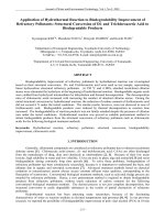
improvement diagram in our study is shown in
the cell reflectance and the cell recombination.
Fig.2.
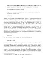
All of these factors that drop down the short
circuit current is shown in Fig.1 [2].
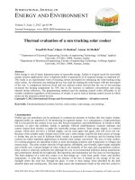
Figure 2. The improvement diagram of Short
Circuit Current can be carried out in two methods (i)
increasing the carrier generation and (ii) enhancing
the carrier collection. ARC anti reflection coating;
FCO font contact optimization
Figure 1. Short circuit current consumption
The other losses of short circuit current in
In this report, we only investigated the loss
of short circuit current on the front surface of
monocrystalline
solar
cell.
Firstly,
the
optimization of front contact was used to
enhance the cells fill factor and the carrier
the solar cell are due to the cell reflectance and
the surface recombination at rear and edge of
the solar cell, which have not been examined
yet in this study because of its complexity and
correlations.
collection. Then, two methods were used to
improve cells light absorption ability: (i)
Trang 49
Science & Technology Development, Vol 16, No.K1- 2013
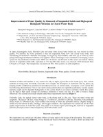
2. EXPRIMENTAL DETAILS
Mono crystalline silicon solar cell was
made from semiconductor-grade silicon (SeGSi) 4 inch wafer, with the crystal orientation of
<100>; p-doped and the resistivity of 1-10
cm; one side polished. With the purity of
99,999999999 %, this type of silicon has very
little lattice defects so the carrier collection
losses inside the solar cell can be considered
small, and this permits to get the short circuit
current solar cells.
In this work, six types of mono crystalline
solar cell were investigated to improve the
short circuit current, except the first sample
Figure 3. The solar cell fabrication process at LNT
that only had the phosphorus diffusion and notoptimized front contact, the other had more
optimization.
Table 1. Cells’ conditions
Sample
Texturization
Diffusion
Anti-Reflection
Front Contact
Coating
Optimization
Annealing
3273
-
X
-
-
X
1067
-
X
-
X
X
5188
X
X
-
X
X
6060
X
X
TiO2/SiO2
X
X
1016
X
X
SiNx
X
X
2217
X
X
ITO
X
X
Phosphorus was diffused into the front
surface by phosphoryl chloride POCl3 in
o
issputtered for depositing full wafer back
contacts.
diffusion furnace at 850 C. Titanium and silver
The front contact grid was optimized
layers (20nmTi/600nmAg) is evaporated by
according to [5], by using the following
electron beam system to create front contacts.
formula:
Meanwhile,
aluminum
layers
(1m
Al)
nw1 J L ac
Trang 50
f
3 PL1t
(2)
TAẽP CH PHAT TRIEN KH&CN, TAP 16, SO K1- 2013
Where
n: numbers of finger; w1
The solar cells efficiency was measured
:finger width; JL : light-generated current, a
under off-standard 21m W/cm2 irradiation
and c : based on cell dimension;
intensity of arc xenon lamp. Then all cell
f : metal resistivity; PL : light intensity,
1 : cell efficiency, t : contact thickness
parameters are fitted with IV-Fit program of
Energy research Centre of the Netherlands by
using the two-diode model
For reducing the surface reflectance,
texturization process used TMAH solution
e(V JRs )
e(V JRs )
V JRs
J J 01 exp
1 J 02 exp
1 J lt
kT
RSH
2kT
(3)
(TMAH 2,5%; IPA 10%), enhanced by
ultrasonic in 20 minutes to create random
pyramids
structure
surface[6],[7].
The
on
the
solar
anti-reflection
cell
coating
layers were deposited for having better
reflectance reduction: titanium silicate layer
and the orthogonal distance regression
method [10] to double
check the
cell
parameters in comparison with the values given
by the solar simulator SS150 (Photo Emission
Co.) and to find out the cell series resistance
RS and the cell shunt resistance RSH.
(TiO2/SiO2) is fabricated by spin coating
method, while ITO layer by the sputtering
3. RESULTS AND DISCUSSION
method [8] and SiNx layer by the PECVD
method [9].
All measured parameters are presented on
the
Table
2
and
corresponding
fitted
parameters are shown on the Table 3.
Table 2. Measured cell parameters
Cell ID
Voc (mV)
JSC (mA/cm2 )
FF(%)
(%)
3273
535
5.21
43
5.76
1067
519
5.37
72
9.60
5188
531
4.93
33
4.14
6060
514
5.83
69
9.98
1016
526
7.61
68
13.14
2217
527
7.92
64
12.81
Trang 51
Science & Technology Development, Vol 16, No.K1- 2013
Table 3. Fitted cell parameters
VOC
JSC
(mV)
(mA/cm2)
3273
533
1067
Cell ID
Jlt
J01
J02
(A/cm2)
(A/cm2)
(A/cm2)
5.76
5.5E-3
4.5E-14
8.4E-8
∞
9.66
5.3E-3
5.7E-12
9.1E-8
50.6
113
4.14
7.3E-3
9.3E-14
8.9E-8
5.9
5
2082
9.98
5.9E-3
7.2E-12
1.1E-7
527
7.6
6.5
74783
13.14
7.8E-3
2.3E-12
2.2E-7
528
7.8
6.2
∞
12.81
7.6E-3
4.2E-12
1.7E-7
RS (Ω)
RSH (Ω)
η (%)
5.4
2.7
185
520
5.3
3.5
5188
531
5.06
6060
515
1016
2217
Our first sample, the cell ID 3273 is the
simplest
one
with only the phosphorus
diffusion in polished silicon surface and notoptimized front contact grid structure. Its short
circuit current was only 5.21 mA/cm2 and 43%
of fill factor. The low short circuit current and
fill factor are probably due to:
1.
the shunt resistance (RSH)istoo low,
thus dumps the fill factor and the
carrier collection ability,
2.
Figure 4. JV curves of cell ID 3273, the simplest
cell with bad cell resistances and the high front
surface reflectance and front surface recombination
the cell surface reflectance is too high
(40% of weight-averaged reflectance)
which causes poor carrier generations,
and
The front contact optimization has been
carried out to obtain highershunt resistance
with the sample ID 1067. As the results, the fill
factor increased significantly from 43% to
3.
silicon surface are not passivated, so
the surface recombination is quite
high so reducing the carrier collection
ability[11].
72%. Due to the increase of the FF, the
efficiency raised up to 9.66%. Still, the short
circuit current was low, because the low light
absorption and low carrier collection possibility
was not solved yet.
Trang 52
TAẽP CH PHAT TRIEN KH&CN, TAP 16, SO K1- 2013
sample 5188 is greater and cause the carrier
collectionpossibility drops down due to the
high surface recombination. As the results, the
short circuit current was decreased to 4.93
mA/cm2.
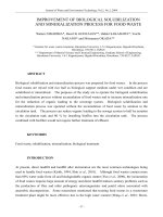
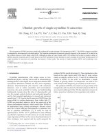
Figure 5. JV curves of the cell ID 2217 (the fitting
curve with symbols using orthogonal distance
regression method). The small deviation between
fitted and measured curve proves the reliability of
extracted parameters.
Figure 7. SEM image of random pyramids structure
after the TMAH surface
treatment
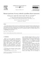
Figure 6. Influence of texturization and ARC on the
Figure 8. The short circuit improvement; 1016
reflectance spectra
(SiNx) and 2217(ITO) are the best cells due to their
In the sample ID 5188, in order to reduce
the
high
reflectance
surface,
anisotropic
best short circuit currents. All measures were under
21 mW/cm of irradiation.
etching in TMAH solution was performed. This
creates random pyramids on the silicon surface,
which
decreases
dramatically
the
total
reflectance (down to 13% from 40% of
polished surface). This makes sample 5188
possessing the good light absorption property.
But the pyramids surface of sample 5188 has a
larger surface area than the flat surface of
sample 3273 or sample 1067. Thus the number
of dangling bonds on the silicon surface of
Three types of anti-reflection coating
(TiO2/SiO2, SiNx and ITO) were used on the
random pyramids structure for the passivation
of dangling bonds on silicon surface. More
importantly, the anti-reflection coating also
reduce the surface reflectance: the SiNx sample
(ID 1016) had 4.4% of reflectance and the ITO
sample (ID 2217) had about 3% of reflectance.
In consequence, the short circuit current of the
Trang 53
Science & Technology Development, Vol 16, No.K1- 2013
TiO2/SiO2 spin coated cell (ID 6060) increases
to 5.9 mA/cm2. In the SiNx layer, with a large
amount of free hydrogen radical originating
from plasma gas dissociation, is the best
passivation layer. Hence, the SiNx sample had
better JSC : 7.6mA/cm2. The ITO layer play less
role in passivating dangling bonds than SiNx
layer, but it plays more role of an extra contact
due to its conduction and thus had a better
reflectance, giving better carrier collections and
Figure 10. Short circuit current improvement; 2217
the best JSC: 7.8mA/cm2.
sample with ITO coating has the best J SC
The short circuit improvement affects cell
efficiency,
displays
in
the
JV
curves
improvement (Fig 8). The cell ID 1016 (SiNx)
and ID 2217 (ITO) curves are the best JV
curves due to their best short circuit current:
7.6 mA/cm2 and 7.8 mA/cm2. One also can see
that the open circuit voltage fluctuate slightly
In the figure 9, we show the image taken
on the front side of the solar cell ID 2217. Two
bus bar structure and fingers with the symbol
of LNT can be easily seen on the surface. In the
figure 10, we show the evolution of Jsc
improvement by adding and using step by step
more efficient processing method.
from one to other cells even the back contact
deposition method is the same.
4. CONCLUSION
Three methods to improve the short circuit
current at front surface were showed: (i) front
contact optimization to reduce cell resistances,
(ii) surface treatment with TMAH solution and
(ii) anti-reflection coating to enhance light
absorption.
However,
surface
treatment
increases surface recombination, thus reducing
JSC (cell ID 5188: 5.06 mA/cm2) and requiring
anti-reflection coating to passivate the dangling
bonds. Finally, all three ARC samples showed
a good passivation ability and made JSC higher
Figure 9. 2217 Solar cell, with front contact
optimization, texturization and ITO antireflection
coating ; η = 12.81%
than
non texturized sample (ID 1067: 5.37
mA/cm2). From the cell ID 3273, with JSC
about 5.2 mA/cm2, which was not optimized, to
the last one (ITO and SiNx), which had enough
Trang 54
TẠP CHÍ PHÁT TRIỂN KH&CN, TẬP 16, SỐ K1- 2013
optimization on the front, the short circuit
methods in improving short circuit current.
current has been greatly enhanced to the value
However, the open circuit voltage is nearly the
2
of 7.8 mA/cm , 150% of increasing;. As the
same (535mV and 527mV), which may need to
results, the cell efficiency increased from
be examined in future research to increase
5.76% to 12.81%, showing the reliability of our
more the cell efficiency.
CẢI THIỆN DỊNG NGẮN MẠCH TRONG PIN MẶT TRỜI SILIC ĐƠN TINH THỂ
Hồng Ngọc Vũ, Trần Ngọc Linh, Trương Lân, Phan Thanh Nhật Khoa, Đặng Mậu Chiến,
Nguyễn Trần Thuật
Phòng Thí Nghiệm Cơng Nghệ Nano, ĐHQG-HCM
TĨM TẮT: Trong bài báo này chúng tơi trình bày chuỗi các thí nghiệm nhằm từng bước cải
thiện dòng ngắn mạch trong pin mặt trời silic đơn tinh thể, từ đó gia tăng hiệu suất của pin. Thứ nhất,
chúng tơi tối ưu hóa lớp điện cực mặt trước để giảm thiểu sự che sáng do điện cực và điện trở của pin.
Thứ hai, chúng tơi nghiên cứu các phương pháp xử lý bề mặt đế silic để tạo ra bề mặt nhám nhằm giảm
độ phản xạ tồn phần và làm tăng khả năng hấp thụ ánh sáng của đế silic. Cuối cùng chúng tơi nghiên
cứu hai loại màng chống phản xạ khác nhau cho pin mặt trời: màng silicon nitride với khả năng thụ
động hóa bề mặt và màng indium tin oxide với khả năng dẫn điện để giảm hơn nữa độ phản xạ tồn
phần trên đế silic. Kết quả thu được pin mặt trời có hiệu suất 13%, với thế hở mạch 527mV, hệ số điền
đầy 68% và dòng ngắn mạch vào khoảng 7.92 mA/cm2 dưới cường độ ánh sáng tới 21mW/cm2.
Từ khóa: pin mặt trời đơn tinh thể, điện cực mặt trước, phương pháp xử lý bề mặt, lớp chống
phản xạ.
REFERENCES
Power Corporation, Manufacture of Solar
Cells With 21% Efficiency (June 2004).
[1]. Adolf Goetzberger, Joachim Knobloch,
[3]. Rohatgi A., Yelundur V., Jeong J, Ebong
Bernhard VoB, Crystalline Silicon Solar
A., Meier D., Babor A. M., Rosenblum M.
Cells, by John Wiley & Sons Ltd, 69-72
D.,
(1998).
Solar Energy Conf., Glasgow,
[2]. William P. Mulligan, Doug H. Rose,
Proc.16th
European
Photovoltaic
1120
(2000).
Michael J. Cudzinovic, Denis M. De
[4]. Winderbaum S., Cuevas A., Chen F., Tan
Ceuster,Keith R. McIntosh, David D.
J., Hanton K., Macdonald D., Roth K.,
Smith, and Richard M. Swanson, Sun
Trang 55
Science & Technology Development, Vol 16, No.K1- 2013
Proc. 19th European Photov. Solar Energy
[8]. Le Thanh Hung, Hoang Ngoc Vu, Dang
Mau
Conf., Paris, 576 (2004).
Chien,
Nguyen
Tran
Thuat,
[5]. Hoang Ngoc Vu, Tong Duy Hien, Duong
Deposition Of ITO Thin Films Used As
Dinh Hiep, Dang Mau Chien, Nguyen
Top Electrode And Antireflection Layers
Tran Thuat, Study And Optimization Of
Of Silicon Solar Cell By Magnetron
The 5th
Sputtering, The 12th Conference On
Advanced
Science and Technology, University of
Materials Science and Nanotechnology
Technology – VNU HCM (submitted) (26
(IWAMSN2010) - Hanoi, Vietnam, MEP-
- 28/10/2011).
Front Contact For Solar Cell,
International
Workshop
on
[9]. Le Tran Hoang Long, Dang Mau Chien,
P11 (2010).
[6]. P. Papet, O. Nichiporuk, A. Kaminski, Y.
Nguyen Tran Thuat,Study Of Deposition
Rozier, J. Kraiem, J.-F. Lelievre, A.
Of SiNx Thin Film By PECVD Used As
Chaumartin,
Anti-Reflection
A.
Fave,
M.
Lemiti,
Coating
And
Surface
Pyramidal texturing of silicon solar cell
Passivation Layer In Solar Cell, The 12th
with TMAH chemical anisotropic etching,
Conference On Science and Technology,
Solar Energy Materials and Solar Cells,
University of Technology - VNU HCM
ISSN: 09270248, Vol:90, Issue: 15, 22,
(submitted) (26 - 28/10/2011).
2319-2328 (September 2006).
[7]. Le Nguyen Ngan, Hoang Ngoc Vu, Tran
[10].
A.R. Burgers J.A. Eikelboom A.
Schönecker
W.C.
Sinke,
Improved
Ngoc Linh, Dang Mau Chien and Nguyen
Treatment Of The Strongly Varying Slope
Tran Thuat,Study of texturizing and
In
etching of monocrystalline silicon and
Photovoltaic
effect of SiNx, ITO ARC for solar cell
Conference Record of Twenty Fifth IEEE
Applications, The 12th Conference On
13-17, 569-572 (May 1996).
Science and Technology, University of
[11].
Fitting
Solar
Cell
Specialists
I-V
Curves,
Conference,
T. Lauinger, J. Schmidt, A. G. Aberle,
Technology – VNU HCM (submitted) (26
R. Hezel, Appl. Phys. Lett. 68, 115936
- 28/10/2011).
(1996).
Trang 56