Experimental study on the one degree of freedom duffing oscillator with impact
Bạn đang xem bản rút gọn của tài liệu. Xem và tải ngay bản đầy đủ của tài liệu tại đây (657.63 KB, 8 trang )
ISSN: 1859-2171
e-ISSN: 2615-9562
TNU Journal of Science and Technology
203(10): 15 - 22
EXPERIMENTAL STUDY ON THE ONE DEGREE-OF-FREEDOM
DUFFING OSCILLATOR WITH IMPACT
La Ngoc Tuan1, Nguyen Van Du2,*
1
Vinh University of Technology Education, Vietnam
2
Thai Nguyen University of Technology, TNU, Viet Nam
ABSTRACT
This paper presents results on realizing experimental devices and evaluating the resonant area of
an one degree-of-freedom Duffing oscillator with impacts. The actuator was developed from a
mini shaker, using electro-mechanical interaction to convert electrical signal to mechanical
vibration. The resonant areas were determined by Bode plots which depict relation between
oscillation amplitude, phase angle and excitation frequencies. The resonant position as well as the
electro-mechanical interaction were evaluated experimentally. The results showed that, impacts
significantly influenced on the resonant frequency. The supplied current appeared to reduce
considerably when resonance occured. The results would be promising for further studies on
vibration with impact problems.
Keywords: Nonlinear dynamics, Duffing oscillator, 1-DOF, vibro-impact, resonance.
Received: 26/6/2019; Revised: 11/7/2019; Published: 12/7/2019
NGHIÊN CỨU THỰC NGHIỆM
CƠ CẤU RUNG VA ĐẬP DUFFING MỘT BẬC TỰ DO
La Ngọc Tuấn1, Nguyễn Văn Dự2,*
1
Trường Đại học Sư phạm Kỹ thuật Vinh, Việt Nam
Trường Đại học Kỹ thuật Công nghiệp - ĐH Thái Nguyên
2
TÓM TẮT
Bài báo này trình bày kết quả nghiên cứu thực nghiệm về triển khai thiết bị và khảo sát vùng cộng
hưởng của cơ cấu rung động Duffing một bậc tự do có va đập. Cơ cấu được phát triển dựa trên một
máy phát rung động nhỏ, sử dụng tương tác điện từ nhằm biến dao động của tín hiệu nguồn thành
dao động của ống dây bên trong. Vùng cộng hưởng được xác định dựa trên biểu đồ Bode, phản
ánh tương quan giữa biên độ dao động, góc pha giữa tín hiệu nguồn và dao động với tần số kích
thích. Vị trí vùng cộng hưởng, tương tác cơ-điện được khảo sát và phân tích từ kết quả thực
nghiệm. Kết quả cho thấy, va đập làm thay đổi đáng kể tần số cộng hưởng của cơ cấu. Một phát
hiện hữu ích khác là cường độ dòng điện kích thích giảm đáng kể khi xuất hiện cộng hưởng. Các
kết quả thu được có thể là nguồn tham khảo cho các bài toán có va đập xuất hiện kèm rung động.
Từ khóa: Động lực học phi tuyến, cơ cấu Duffing, hệ một bậc tự do, rung động-va đập, cộng hưởng.
Ngày nhận bài: 26/6/2019; Ngày hoàn thiện: 11/7/2019; Ngày đăng: 12/7/2019
* Corresponding author. Email:
/>; Email:
15
La Ngoc Tuan et al.
TNU Journal of Science and Technology
1. Introduction
The Duffing oscillator has been well-known
as the ones having a mass attached to a
nonlinear spring, whose restoring force is
expressed in a cubic function of its elastic
deformation [1]. A one-degree-of-freedom (1DOF) Duffing oscillator is described by the
following differential equation:
(1)
X X X X 3 F cost
where X is the oscillation amplitude, X and
X are the first and second derivative of X,
respectively. In Equation (1), the nonlinear
term βX3 changes the dynamics of the system
harshly and make it difficulties in finding
exact solutions such as [2]:
– An analytic solution is no longer available;
– The superposition principle is no longer
valid.
In practices, The Duffing equation is usually
used to describe many nonlinear systems.
Because all practical springs exhibit a
nonlinear force-deflection relation, the
Duffing model with nonlinear spring force
would be more accurate in applications. In
addition to the nonlinear cubic term, a
Duffing oscillator with impacts exhibit a
stronger nonlinear and thus much richer
mechanic behaviors.
Previously, several investigations have been
paid to the Duffing oscillator with impacts.
For example, a theoretical study of Avramova
and Borysiuk [3] employing a nonsmooth
unfolding transformation to analyze the
dynamics of a one-degree-of-freedom impact
Duffing oscillator. The stochastic bifurcations
and response of vibro-impact Duffing–Van
der Pol oscillators, subjected to white noise
were examined in several studies [4], [5], [6].
It has been found that most studies focused on
the fundamental behavior of the system. A
vibro-impact Duffing model using minishaker, proposed for drifting systems [7] has
been found as a practical application as well
as an experimental study in this trend. For
simpler oscillators with linear spring force,
the interaction between electro-magnetic and
16
203(10): 15 - 22
mechanical forces during impact and drifting
in a similar device was also carried out [8].
The phase lag between the magnetic
excitation force and the motion of the impact
mass has been identified as a control factor to
obtain maximum progression rate of such
machines [9]. In order to make the device
more practical applicable, this paper
experimentally identifies major parameters of
such vibro-impact device but with the cubic
spring force in its resonance area. The results
would play important basic for further studies
of applying this device in practice.
This paper is organized as follows: Section 2
portrays the design and implementation of the
system. In Section 3, the experimental results
are reported and discussed. Several important
remarks are concluded in Section 4.
2. Experimental implementation
The experimental setup was designed based
on the common principle of the 1-DOF
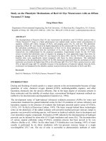
system with impact. Figure 1 depicts the
realized setup. A mini electro-dynamical
shaker (1) was used to generate the required
harmonic oscillation. The shaker is fixed on a
steel and heavy table via screws (2). The
movable coil (3) of the shaker is supported by
a shaft which is placed on a couple of leaf
springs (4). Given that the shaker body is
fixed, supplying a sinusoidal current to the
shaker coil leads to oscillations of the shaft.
Figure 1. The experimental setup
A mass (5) is joined and thus can oscillate
together with the shaft. The mass is placed on
a rolling slider of a rail guide to minimize the
frictional force when moving. An obstacle
; Email:
La Ngoc Tuan et al.
TNU Journal of Science and Technology
block (6) was fixed nearby the car oscillation
path to obtain impact force.
The shaker was powered by a sinusoidal
signal which was amplified by a commercial
amplifier with a fixed gain. Two levels of the
voltage supplied to the shaker were obtained
by two levels of the control signals at 150 mV
and 200 mV. The voltage signal drop on a
resistor (7) was used to measure the current
supplying
to
the
shaker.
Relative
displacement between the mass (5) and the
shaker body was measured by means of a
noncontact displacement sensor (8) model
KD-2306 from Kaman Precision Products. A
linear variable displacement transducer
(LVDT) (9) is preserved to measure the body
shaker movement in the further study for 2
DOF systems.
At the first step, the spring force depending
on the displacement was measured as below.
The mass 5 was pushed to slowly move along
the rail guide by mean of a transmission
screw. The pushing force was collected by a
load cell placed between the screw and the
mass. Experimental data of the force with
respect to the displacement were then plotted.
203(10): 15 - 22
spring function having the stiffness as same
as the linear term in the fitted cubic function
was plotted for reference. Details of fitting
function is depicted in Table 1.
Table 1. Fitted result of the spring function
Model
Duffing (User)
Equation
k1*X+k2*X^3
Plot
Spring force
k1 (N/mm)
5.12365
k2 (N/mm)
7.89E-02
Reduced Chi-Sqr
0.27622
R-Square(COD)
0.99909
Adj. R-Square
0.99909
As can be seen in Table 1, with the R-square
factor of 0.99909, the spring force function
can be expressed as:
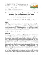
Fspr 5.12365 X 0.0789 X 3
(2)
The spring force, which was well fitted in a
cubic function, exhibited that the device is in
fact a Duffing oscillator. From Equation (2)
the sign of the cubic term is positive, as well
as referring to the reference linear function in
Figure 2, it can be observed that the
investigated system is a hardening spring
Duffing oscillator [10].
In the next section, several important results
of experimental tests are presented. The main
purpose of the tests is to prepare essential
basics for further studies on 2 DOF vibroimpact systems, as described below.
-
Figure 2. Function fitting of spring force with
respect to displacement (solid) and a reference
linear line (dot)
A nonlinear regression in the cubic form was
then applied to carry out the spring force as a
function of the displacement. Figure 2
presents the nonlinear fitting results. A linear
17
-
-
To validate an important character of
a nonlinear system is that the
dependence of the resonance
frequency on the level of excitation
force;
To carry out how the excitation force
changes when the system falls in the
resonant situation;
To point out if the phase lag between
excitation and displacement of the
mass in resonant stage follows the
rule found in [9] in impact stage.
; Email:
La Ngoc Tuan et al.
TNU Journal of Science and Technology
3. Results and discussions
3.1. Resonant frequency
For typical oscillators, the frequencies at
which the response amplitude is a relative
maximum are known as resonant frequencies.
In adjacent areas of such resonant
frequencies, small periodic forces would
produce large amplitude oscillations, due to
the storage of vibrational energy.
In nonlinear systems, the maximum response
does not occur close to the system natural
frequency as usually appears in linear
systems. The Duffing oscillator, with the
appearance of the cubic nonlinearity, has been
well known as a classical model for
remarkable jump phenomenon, as illustrated
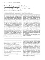
in Figure 3 [11].
Figure 3. Typical response of a Duffing oscillator [11]
As can ben seen in Figure 3, the maximum
oscillation amplitude (the response) of the
system would be either S2 or S3, depending on
the direction of the frequency changes. If the
excitation frequency progressively increases,
a maximum response (i.e. a resonance) S3
would occur when the excitation frequency
reaches the value of 2, and then suddenly
jumps down. In constrast, if the excitation
frequency gradually decreases, the oscillation
amplitude would slowly increases and reaches
S2 at the frequency of 1. This special
character is the most difference to linear
systems.
18
203(10): 15 - 22
It would be worth noting that the full response
curve shown in Figure 3 is not able to obtain
experimentally. There only points on the two
parts of the curve (shown in solid line) can be
collected. Besides, experimental setup both to
control the excitation frequency and to
capture the system response is usually
complicated and required expensive harwares
and licensed softwares. This study presents a
simple practical approach to implement the
required functions to evaluate the system
response.
A digital oscilloscope model PicoScope
2204A, a cost-saving equipment, was used to
generate progressively changes of excitation
frequency. The genertaed signal was then
supply to the shaker via commercial
amplifier. At each value of the excitation
frequency, the proportion of the mass
displacement of the mass to the excitation
force was calculated. The oscillation
amplitude was measured by the sensor (8), as
mentioned in Section 2, and was assigned as
the output voltage, V2. The excitation force
was determined by the current passing the
shaker and assigned as the input voltage, V1.
Consequently, the proportion ratios of the
mass displacement of the mass to the
excitation force was carried out in the unit of
Decibel (dB) as following equation:
V
R 20 log 2
V1
(3)
The approach mentioned was easy to be
implemented by mean of the Bode plot
function in the software named Frequency
Response Analyzer for PicoScope (FRA4PS),
which is avalable and free of charge.
The data collected were then used to draw
curves of the output-input ratio as a function
of the excitation frequency. Resonant points
are the ones where the curves reached
maximum values.
; Email:
La Ngoc Tuan et al.
TNU Journal of Science and Technology
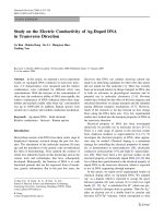
Figure 4 depicts two cases of different levels
of the supplied voltages. As can be seen in the
figure, increasing frequency resulted in higher
resonant frequencies. For example, with a
lower voltage supply (Vexc=150 mV), the
resonance occured at 18.957 Hz in the case of
increasing frequency and at 18.451 Hz when
decreasing frequency. Similarly, with the
control signal of 200 mV, the increasing and
decreasing
directions
of
excitation
(a)
203(10): 15 - 22
frequencies provided resonances at 19.303 Hz
and 18.472 Hz, respectively. From these
results, it would be verified that the proposed
experimental appoach is validated and thus
can be used to further evaluate the system
behavior in case of vibro-impact situations.
Applying the similar approach for the system
attaching the obstacle block, i.e. the vibroimpact system, the experimental frequency
response curves are depicted in Figure 5.
(b)
Figure 4. Frequency response of forced, 1 DOF vibration system when increasing (lines with upside
diamond symbols) and decreasing (lines with downside diamond symbols),
the control signal levels of: a) 150 mV and b) 200 mV
(a)
(b)
Figure 5. Frequency response of forced, 1 DOF vibro-impact system when increasing
(lines with upside diamond symbols) and decreasing (lines with downside diamond symbols),
the control signal levels of: a) 150 mV and b) 200 mV
19
; Email:
La Ngoc Tuan et al.
TNU Journal of Science and Technology
It can be observed from Figure 5 that, as
similar to that of the free vibration, higher
excitation power also resulted in higher
resonant frequencies. At the same power
supply, the resonant frequency when
increasing control frequency is higher than
that decreasing control frequency. Another
important point is that, with the same level of
the power supplied, the resonant frequency in
vibro-impact stage is higher than that in free
vibration. This observation would play an
important basic for further study on vibroimpact dynamic responses.
203(10): 15 - 22
3.2. Electro-mechanical interaction
The interactions between power supply and
the dynamical behavior of the vibro-impact
actuator have been rarely found in literature.
In order to carry out the coupled interaction
between such stages, as previously
implemented [8], signals of the current
passing the shaker and displacement of the
mass in both situations of free vibration and
impact were collected. Figure 6 presents two
illustrations from the two situations: free
vibration (Figure 6a) and vibro-impact
(Figure 6b).
Figure 6. (Color online) Time histories of the displacement of the mass (grey) and the current supplied
(red) for: a) free vibration and b) vibro-impact. Resonant area are marked by magenta retangles
As can be seen in Figure 6, the current
supplying to the shaker was significantly
reduced when resonance occurred. Such
phenomena were not only appeared in free
vibration (Figure 6a) but also in the situation
of vibration combined with impact (Figure
6b). This observation would be very
promising for further optimization of the
device regarding energy saving purpose.
3.3. Phase lag in resonant stage
The phase lag between power supply and the
actuator displacement has been found to be an
effective parameter to control the system
obtaining optimized progress rate [9].
Consequently, this study initially validate if
the phase lag in resonant stage satisfied the
condition proposed in [9]. For this reason,
signals of the supplied current and of the mass
displacement were collected and analyzed.
20
Figure 7 presents relations between the two
signals when the resonance occurred in both
situations: free vibration (Figure 7a) and
vibro-impact (Figure 7b).
As can be seen in the Figure 7a, the current
signal appeared to go ahead of the mass
displacement an approximate angle of /2. In
impact stage (Figure 7b), the time when the
current signal switched from a positive to a
negative sign appeared after the instant when
the mass collided with the stop. This
observation seemed to agree with the
experimental results obtained in [9]. It would
make confident that, the best situation of
progression rate of a 2 DOF can also
developed from the stage of resonant situation
of such device. The results obtained in this
study thus would provide a good basic for
further study on 2 DOF systems using
Duffing oscillators.
; Email:
La Ngoc Tuan et al.
TNU Journal of Science and Technology
(a)
203(10): 15 - 22
(b)
Figure 7. A close-up of time histories at the resonant stage of the displacement of the mass (dots)
and the current supplied (solid line) for: a) free vibration and b) vibro-impact
4. Conclusion
The experimental results presented in this
paper were obtained from collected data on a
practical one DOF Duffing oscillator. The
valuable remarks can be concluded as below.
1) An experimental device of Duffing
oscillator which is able to collect reliable data
can be obtained from available and costsaving hardware and software. The system
and experimental observation at 1-DOF stage
can be further employed for 2-DOF systems.
2) The resonant frequency in vibro-impact
stage is higher than that in free vibration;
3) When resonance occurred, the current
supplied to the electro-actuator significantly
reduced, promising a further study on saving
energy for such devices.
4) The phase lag between current supplied
and the mass displacement in the resonant
stage appeared similarly to that in the best
situation of 2-DOF systems. Phase lag would
be a good control parameter to obtain a
desired situation.
Acknowledgements
This research is funded by Vietnam National
Foundation for Science and Technology
Development (NAFOSTED) under grant
number 107.01-2017.318.
21
REFERENCES
[1]. Ivana Kovacic and Michael Brennan, The
Duffing Equation: Nonlinear Oscillators and
their Behaviour, Wiley publisher, 2011.
[2]. Hans Jürgen Korsch, Hans-Jörg Jodl, and
Timo Hartmann, "The Duffing Oscillator," in
Chaos, pp. 157-184, Springer Berlin
Heidelberg, 2008.
[3]. K. V. Avramov and O. V. Borysiuk,
"Analysis of an impact Duffing oscillator by
means
of
a
nonsmooth
unfolding
transformation," Journal of Sound and
Vibration, vol. 318, pp. 1197-1209, 2008.
[4]. P. Kumar, Narayanan, and S. S. & Gupta,
"Stochastic bifurcations in a vibro-impact
Duffing–Van der Pol oscillator," Nonlinear
Dynamics, vol. 85, pp. 439, 2016.
[5]. Guidong Yang, Wei Xu, Xudong Gu, and
Dongmei Huang, "Response analysis for a
vibroimpact Duffing system with bilateral
barriers under external and parametric
Gaussian white noises," Chaos, Solitons &
Fractals, vol. 87, pp. 125-135, 2016.
[6]. Jinqian Feng, Wei Xu, Haiwu Rong, and Rui
Wang, "Stochastic responses of Duffing-Van
der Pol vibro-impact system under additive
and multiplicative random excitations,"
International Journal of Non-Linear
Mechanics, vol. 44, pp. 51-57, 2009.
[7]. Van-Du Nguyen, The-Hung Duong, NgocHung Chu, and Quoc-Huy Ngo, "The effect
of inertial mass and excitation frequency on a
Duffing vibro-impact drifting system,"
International Journal of Mechanical
Sciences, vol. 124-125, pp. 9-21, 2017.
[8]. Van-Du Nguyen, Huu-Cong Nguyen, NhuKhoa Ngo, and Ngoc-Tuan La, "A New
; Email:
La Ngoc Tuan et al.
TNU Journal of Science and Technology
Design of Horizontal Electro-Vibro-Impact
Devices," Journal of Computational and
Nonlinear Dynamics, vol. 12, pp. 061002061011, 2017.
[9]. Van-Du Nguyen, Huu-Duc Ho, The-Hung
Duong, Ngoc-Hung Chu, and Quoc-Huy
Ngo, "Identification of the Effective Control
Parameter to Enhance the Progression Rate
of Vibro-Impact Devices With Drift,"
Journal of Vibration and Acoustics, vol. 140,
pp. 011001, 2017.
22
203(10): 15 - 22
[10]. Michael J. Brennan and Ivana Kovacic,
"Examples of Physical Systems Described by
the Duffing Equation," in The Duffing
Equation, Wiley publisher, 2011.
[11]. Tamás Kalmár-Nagy and Balakumar
Balachandran, "Forced Harmonic Vibration
of a Duffing Oscillator with Linear Viscous
Damping," in The Duffing Equation, Wiley
publisher, 2011.
; Email: