Research on designing the regenerative braking system apply to conventional vehicle
Bạn đang xem bản rút gọn của tài liệu. Xem và tải ngay bản đầy đủ của tài liệu tại đây (542.87 KB, 7 trang )
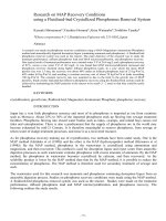
������������������������������������������������������������������������������������������������������������������������������������������������������������������������������������������������������������������������������������������������������������������������������������������������������������������������������������������������������������������������������������������������������������������������������������������������������������������������������������������������������������������������������������������������������������������������������������������������������������������������������������������������������������������������������������������������������������������������������������������������������������������������������������������������������������������������������������������������������������������������������������������������������������������������������������������������������������������������������������������������������������������������������������������������������������������������������������������������������������������������������������������������������������������������������������������������������������������������������������������������������������������������������������������������������������������������������������������������������������������������������������������������������������������������������������������������������������������������������������������������������������������������������������������������������������������������������������������������������������������������������������������������������������������������������������������������������������������������������������������������������������������������������������������������������������������������������������������������������������������������������������������������������������������������������������������������������������������������������������������������������������������������������������������������������������������������������������������������������������������������������������������������������������������������������������������������������������������������������������������������������������������������������������������������������������������������������������������������������������������������������������������������������������������������������������������������������������������������������������������������������������������������������������������������������������������������������������������������������������������������������������������������������������������������������������������������������������������������������������������������������������������������������������������������������������������������������������������������������������������������������������������������������������������������������������������������������������������������������������������������������������������������������������������������������������������������������������������������������������������������������������������������������������������������������������������������������������������������������������������������������������������������������������������������������������������������������������������������������������������������������������������������������������������������������������������������������������������������������������������������������������������������������������������������������������������������������������������������������������������������������������������������������������������������������������������������������������������������������������������������������������������������������������������������������������������������������������������������������������������������������������������������������������������������������������������������������������������������������������������������������������������������������������������������������������������������������������������������������������������������������������������������������������������������������������������������������������������������������������������������������������������������������������������������������������������������������������������������������������������������������������������������������������������������������������������������������������������������������������������������������������������������������������������������������������������������������������������������������������������������������������������������������������������������������������������������������������������������������������������������������������������������������������������������������������������������������������������������������������������������������������������������������������������������������������������������������������������������������������������������������������������������������������������������������������������������������������������������������������������������������������������������������������������������������������������������������������������������������������������������������������������������������������������������������������������������������������������������������������������������������������������������������������������������������������������������������������������������������������������������������������������������������������������������������������������������������������������������������������������������������������������������������������������������������������������������������������������������������������������������������������������������������������������������������������������������������������������������������������������������������������������������������������������������������������������������������������������������������������������������������������������������������������������������������������������������������������������������������������������������������������������������������������������������������������������������������������������������������������������������������������������������������������������������������������������������������������������������������������������������������������������������������������������������������������������������������������������������������������������������������������������������������������������������������������������������������������������������������������������������������������������������������������������������������������������������������������������������������������������������������������������������������������������������������������������������������������������������������������������������������������������������������������������������������������������������������������������������������������������������������������������������������������������������������������������������������������������������������������������������������������������������������������������������������������������������������������������������������������������������������������������������������������������������������������������������������������������������������������������������������������������������������������������������������������������������������������������������������������������������������������������������������������������������������������������������������������������������������������������������������������������������������������������������������������������������������������������������������������������������������������������������������������������������������������������������������������������������������������������������������������������������������������������������������������������������������������������������������������������������������������������������������������������������������������������������������������������������������������������������������������������������������������������������������������������������������������������������������������������������������������������������������������������������������������������������������������������������������������������������������������������������������������������������������������������������������������������������������������������������������������������������������������������������������������������������������������������������������������������������������������������������������������������������������������������������������������������������������������������������������������������������������������������������������������������������������������������������������������������������������������������������������������������������������������������������������������������������������������������������������������������������������������������������������������������������������������������������������������������������������������������������������������������������������������������������������������������������������������������������������������������������������������������������������������������������������������������������������������������������������������������������������������������������������������������������������������������������������������������������������������������������������������������������������������������������������������������������������������������������������������������������������������������������������������������������������������������������������������������������������������������������������������������������������������������������������������������������������������������������������������������������������������������������������������������������������������������������������������������������������������������������������������������������������������������������������������������������������������������������������������������������������������������������������������������������������������������������������������������������������������������������������������������������������������������������������������������������������������������������������������������������������������������������������������������������������������������������������������������������������������������������������������������������������������������������������������������������������������������������������������������������������������������������������������������������������������������������������������������������������������������������������������������������������������������������������������������������������������������������������������������������������������������������������������������������������������������������������������������������������������������������������������������������������������������������������������������������������������������������������������������������������������������������������������������������������������������������������������������������������������������������������������������������������������������������������������������������������������������������������������������������������������������������������������������������������������������������������������������������������������������������������������������������������������������������������������������������������������������������������������������������������������������������������������������������������������������������������������������������������������������������������������������������������������������������������������������������������������������������������������������������������������������������������������������������������������������������������������������������������������������������������������������������������������������������������������������������������������������������������������������������������������������������������������������������������������������������������������������������������������������������������������������������������������������������������������������������������������������������������������������������������������������������������������������������������������������������������������������������������������������������������������������������������������������������������������������������������������������������������������������������������������������������������������������������������������������������������������������������������������������������������������������������; 3 phases -220V ;
7.5kW
VSED ; 80V- 4.7A ; 1800rpm
Burster Torque sensor 85646 ; 0500Nm ; 2.34mV/Nm
Card NI USB6008
Aduino-uno
LabVIEW 2014
Magnetic sensor are used to measure
vehicle speed and generator speed
0.1< i<0.6
2HP
Imax 50A ; U 20V
Journal of Science & Technology 135 (2019) 007-013
The experiment was carried out with 4 different
driving cycles: FTP-75, NEDC, EUDC and ECE R15.
Each cycle is installed to the inverter that drives the
motor through the PID controller. During vehicle
speed sensor operation, the feedback signal allows the
PID controller to continuously control the actual
speed of the vehicle match with the standard speed of
the driving cycle. In addition, the magnetic brakes are
activated which act on the wheel to make slow down
vehicle speed. Whenever a deceleration signal occurs,
the controller activates the energy recovery system
through a double planetary gear set, which makes the
flywheel and generator spin. The energy recovery
process is started. The energy generated by the
generator will be supplied through an adjustable load.
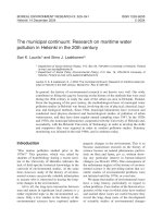
During operation, the data acquisition system through
LabVIEW software always records the values such as
vehicle velocity, generator speed, voltage and current
through the load.
(s); The EUDC driving cycle:
E = 1 7 4 5 .5 2 (k J)
with full driving cycle duration 400(s) and active
duration of RBS 94 (s); The ECE R15 driving cycle:
E = 2 0 9 .0 2 2 (k J) with full driving cycle duration
195(s) and active duration of RBS 36 (s)
Fig. 9. Chart of comparing simulation results between
cycles
3.2. Experimental result
According to the graph is built from the
experimental results, the energy recovery time is less
than the simulation result. Because of electrical
latency phenomenon, when the system detects the
deceleration of the vehicle through the speed sensor,
the controller immediately activates the RBS.
However, due to the mechanical can cause energy
recovered increasing slowly. In addition, deceleration
stages often occur shortly about 2 to 3 seconds and
afterward acceleration mode are performed. In these
situations, are often controlled without recovering
energy during the experiment.
Fig. 8. Data acquisition using LabVIEW
3. Result analysis and discussion
3.1. Simulation result:
Based on the simulation results of full driving
cycle, the energy recovered is calculated. From the
result of the power curve the energy generated can be
determined by the equation (20) [8].
tn
E =
P(t) d t
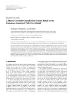
Fig. 10. Energy recovered on the FTP 75 driving cycle
(20)
The total energy recovered by FTP-75 driving
cycle E = 5 0 5 0 .7 5 (k J)
t0
If the obtained power is a line parallel to the
time axis, the energy obtained is calculated as
equation
E = P .Δ t = P (t n -t 0 )
(21)
The total energy recovered by FTP-75 driving
cycle: E = 1 8 0 3 8 .4 1 (k J) with full driving cycle
duration 3748(s) and active duration of RBS 1145(s);
The NEDC: E = 2 4 7 8 .0 9 (k J) with full driving
Fig. 11. Energy recovered on the ECE R15 driving cycle
cycle duration 180(s) and active duration of RBS 238
11
Journal of Science & Technology 135 (2019) 007-013
Table 4. The results of energy recovered in driving cycles.
Driving cycle
Driving distance [km]
Full driving cycle duration [s]
Active duration of RBS [s]
Percentage of active duration (%)
Average speed [km/h]
Simulation
Total energy
recovered [kJ]
Experiment
Efficiency
FTP-75
35.54
3748
1145
30.5%
34.1
18038.41
5050.75
0.28
NEDC
EUDC
ECE R15
109.314
69.549
0.9941
1180
400
195
238
94
36
20.2%
23.5%
18.5%
33.35
62,59
18.35
2478.09
1745.52
209.02
792.99
663.29
45.98
0.32
0.38
0.22
energy recovery isn't long because of city driving
conditions
The total energy recovered by ECE R15 driving
cycle: E = 45 9 .84 (k J)
With the EUDC driving cycle, although the
activation period of RBS is only 23.5%, the energy
recovery efficiency can reach 38% due to the vehicle
speed at the beginning of the deceleration process is
higher than FTP75
The braking force distribution also greatly
affects the energy to recovered. There are three
control methods of regenerative braking force
distribution such as optimizing braking force;
maximum recovered energy and collaboration to
ensure the stability while braking. In this study, the
braking force from the energy recovery system is
controlled by the balance between the regenerative
braking force and mechanical braking to keep vehicle
stability.
Fig. 12. Energy recovered on the EUDC driving cycle
The total energy recovered by EUDC driving
cycle: E = 66 3 .29 (k J)
4. Conclusion
This paper presented the design and calculated
parameters of the regenerative braking system based
on conventional vehicle powertrain. The experimental
results demonstrate that the energy recovery
efficiency can reach 38% depends on the initial
velocity of the braking. The higher the velocity of the
vehicle at the beginning of braking process is; the
larger the energy recovery was generated by
regenerative braking assembly. These results will be
the fundamental for optimally calculating the
structural of mechanical system, fuel consumption of
the vehicle which equipped with the regenerative
braking energy recover assembly. To improve the
efficiency further studies on reducing mechanical loss
by using magnet bearing and placing the flywheel on
vacuum chamber. In addition, the control algorithms
should also be improved.
Fig. 13. Energy recovered on the NEDC driving cycle
The total energy recovered by NEDC driving
cycle: E = 79 2 .99 (k J)
Discussion
According to the experimental results, the
recovered energy can be from 28% to 38% of the
energy in according to the simulation results. Energy
recovery is also depending on the driving cycle. The
more deceleration time is activated in the driving
cycle, the more energy is recovered
Acknowledgements
The authors would like to thank the president of
HCMUTE, supervisors, Automotive Mechatronic
Lab, Automotive Testing Lab at Faculty of Vehicle
and Energy Engineering for supporting us in this
research.
With the FTP75 driving cycle, the energy
recovery rate can reach 30.5%, but the energy
recovery efficiency is not high because the vehicle
speed at the beginning of the deceleration process is
low. Besides, the active duration of RBS for each
12
Journal of Science & Technology 135 (2019) 007-013
[9]. C. Brockbank and W. Body, Flywheel based
mechanical hybrid system; simulation of the fuel
consumption benefits of various transmission
arrangements and control strategies, paper presented
at the ASME International Design Engineering
Technical Conferences & Computers and Information
in Engineering Conference (IDETC/CIE '10),
Montreal, Canada, 2010.
References.
[1]. Farhan Khan, Shivam Kumar, Dr.Ashish Mathew,
Int. J. of Innovative Research in science and
Engineering, Vol.No.2, Issue 04, April 2016.
[2]. Mayuresh Thombre, Prajyot Borkar, Mangirish
Bhobe, Int. J. of Mechanical, Aerospace, Industrial,
Mechatronic and Manufacturing Engineering Vol: 8,
No: 4, 2014
[10]. Tai-Ran Hsu, On a Flywheel-Based Regenerative
Braking System for Regenerative Energy Recovery,
paper presented at the Green Energy and systems
Conference, USA, 2013.
[3]. Alberto A. Boretti, Int. J. Vehicle Design, Vol. 55,
No. 1, 2011
[4]. U. Diego Ayala, Martinez-Gonzalez, P., McGlashan,
N., Pullen, K.R., Int. J. of automobile Engineering,
vol. 222, 2008.
[11]. Loi Wei Cheong, Regenerative Braking System
(RBS): Energy Measurement, University Technical
Malaysia Melaka, Malaysia 2012.
[5]. C. M. Jefferson and M. Ackerman, Int. J. of Energy
Conversion and Management, vol. 37, pp. 1481-1491,
1996.
[12]. Fabian Perktold, Research on a regenerative braking
system for a golf cart, University of Applied Sciences
Upper Austria, Australia, 2016
[6]. Rajesh Rajamani, Vehicle Dynamics and Control
(Springer Science+Business Media, LLC, 233 Spring
Street, New York, NY 10013, USA) Page 98-101,
2012
[13]. Raffaele Di Martino, Modelling and Simulation of the
Dynamic Behaviour of the Automobile, PhD thesis in
Mechanical Engineering, University of Salerno, Italy,
2005.
[7]. S.J.Clegg, A Review of Regenenrative Brake
System.Transport Studies, Working Paper 471,
University of Leeds, UK, 1996
[14]. Vu Thanh Trung, Nguyen Đinh Tuan, Nguyen Hoang
Vu, Determination of rotating mass factor to
simulating longitudinal motion dynamics of the
Hyundai Starex vehicle, National conference on
Mechanical Science and Technology, HCM city
2015.
[8]. Radhika Kapoor, C. Mallika Parveen, Member,
IAENG, Comparative Study on Various KERS, paper
presented at the World Congress on Engineering,
London, U.K., 2013.
13